4.48 AIRHANDLER
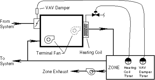
AIRHANDLER defines a central air handling system, containing a fan or fans, optional heating and cooling coils, and optional outside air intake and exhaust. AIRHANDLERs are subobjects of TOP, and deliver air to one or more ZONEs through TERMINAL(s). AIRHANDLER objects can be used to model fan ventilation and forced air heating and cooling. Dual duct systems are modeled with two AIRHANDLERs (one for hot air and one for cool air) and two TERMINALs in each zone. Figure 2 shows…. [need a sentence that explains the figure.]
AIRHANDLER is designed primarily to model a central system that supplies hot or cold air at a centrally determined temperature (the “Supply Temperature Setpoint”) to Variable Air Volume (VAV) terminals in the zones. Some additional variations are also supported:
The AIRHANDLER can model a constant volume, fan-always-on system, where the supply temperature varies to meet the load of a single zone (that is, the thermostat controls the heating and/or cooling coil, but not the fan). This is done by setting the terminal minimum flow, tuVfMn, equal to the maximum flow, tuVfMxH for heating and/or tuVfMxC for cooling, and using a supply temperature control method that adjusts the temperature to the load (ahTsSp = WZ, CZ, or ZN2, described below).
The AIRHANDLER can model constant volume, fan cycling systems where the fan cycles with a single zone thermostat, running at full flow enough of the time to meet the load and shutting completely off the rest of the time, rather than running at variable flow to adjust to the demand from the zones.
This variation is invoked by specifying ahFanCycles= YES (usually with ahTsSp=ZN, described below). The user should be aware that this is done by treating fractional flow as equivalent to fractional on-time in most of the program, adjusting for the higher flow and less than 100% duty cycle only in a few parts of the model known to be non-linear, such as computation of cooling coil performance, fan heat, and duct leakage. For example, the outside air inputs, designed for VAV modeling, won’t work in the expected manner unless you keep this modeling method in mind.
The AIRHANDLER can supply hot air, cold air, or shut off according to the requirements of a single zone. This variation is invoked by giving ahTsSp = ZN or ZN2, both described further below.
ahName
Name of air handler: give after the word AIRHANDLER. Required for reference in TERMINALs.
| Units | Legal Range | Default | Required | Variability |
|---|---|---|---|---|
| 63 characters | Yes | constant |
ahSched=choice
Air handler schedule; OFF or ON, hourly schedulable by using CSE expression.
| OFF | supply fan off; air handler not operating. Old date? Note: (future) Taylor setback/setup control in effect, when implemented. |
| ON | supply fan runs, at varying volume according to TERMINAL demand (except if ahFanCycles = YES, fan cycles on and off at full volume). |
The following might be used to run an air handler between 8 AM and 5 PM:
    ahSched = select(  (\$hour > 8 && \$hour <= 5),  ON,
default, OFF );| Units | Legal Range | Default | Required | Variability |
|---|---|---|---|---|
| ON/OFF | ON | No | hourly |
ahFxVfFan=float
Fan flow rate multiplier for autosized fan(s). The default value (1.1) specifies 10% oversizing.
| Units | Legal Range | Default | Required | Variability |
|---|---|---|---|---|
| x \(\ge\) 0 | 1.1 | No | constant |
4.48.1 AIRHANDLER Supply Air Temperature Controller
ahTsSp=float or choice
Supply temperature setpoint numeric value OR* choice of control method (WZ, CZ, RA, ZN, or ZN2):
| float | A numeric value specifies the supply temperature setpoint. An expression can be used to make dependent on time, weather, etc. |
| WZ | Warmest Zone: for cooling, sets the supply temperature setpoint each sub??hour so that the control zone (seeahWzCzns) requiring the coolest supply temperature can meet its load with its VAV damper 90% of the way from its minimum opening to its maximum, that is, at a flow of: tuVfMn + .9(tuVfMxC - * tuVfMn*). |
| CZ | Coolest Zone: analogous to WZ, but for heating |
| RA | Supply temperature setpoint value is controlled by return air temperature (this cannot be done with a CSE expression without lagging a subhour). See ahTsRaMn and ahTsRaMx. |
| ZN | Causes air handler to switch between heating, OFF, and cooling as required by the load of a single zone. When the zone thermostat (modeled through the tuTC and tuTH inputs) calls for neither heating nor cooling, the air handler shuts down, including stopping its fan(s). Changes ahFanCycles default to YES, to simulate a constant volume, fan cycling system. |
| Supply temperature setpoint value when ahFanCycles = YES is taken from ahTsMn for cooling, from ahTsMx for heating (actual temperatures expected to be limited by coil capacity since fan is running at full flow). When ahFanCycles = NO, the setpoint is determined to allow meeting the load, as for WZ and CZ. | |
| When the zone is calling for neither heat nor cold, the air handler shuts down, including stopping its fan(s), regardless of the ahFanCycles value. | |
| ZN2 | Causes air handler to switch between heating, cooling, and FAN ONLY operation as required by the load of a single zone. To model a constant volume system where the fan runs continuously, use ZN2 and set the terminal minimum flow (tuVfMn) equal to the maximum (tuVfMxC and/or tuVfMxH). |
| When ahTsSp is ZN2, the supply temperature setpoint is determined to allow meeting the load, as for WZ and CZ, described above. |
Only when ahTsSp is ZN or ZN2 does AIRHANDLER switches between heating and cooling supply temperatures according to demand. In other cases, there is but a single setpoint value or control method (RA, CZ, or WZ); if you want the control method or numeric value to change according to time of day or year, outside temperature, etc., your CSE input must contain an appropriate conditional expression for ahTsSp.
Unless ahTsSp is ZN or ZN2, the AIRHANDLER does not know whether it is heating or cooling, and will use either the heating coil or cooling coil, if available, as necessary, to keep the supply air at the single setpoint temperature. The coil schedule members, described below, allow you to disable present coils when you don’t want them to operate, as to prevent cooling supply air that is already warm enough when heating the zones. For example, in an AIRHANDLER with both heating and cooling coils, if you are using a conditional expression based on outdoor temperature to change ahTsSp between heating and cooling values, you may use expressions with similar conditions for ahhcSched and ahccSched to disable the cooling coil when heating and vice versa. (Expressions would also be used in the TERMINALS to activate their heating or cooling setpoints according to the same conditions.)
Giving ahTsSp is disallowed for an air handler with no economizer, no heat coil and no cooling coil. Such an AIRHANDLER object is valid as a ventilator; its supply temperature is not controlled. but rather determined by the outside temperature and/or the return air temperature.
| Units | Legal Range | Default | Required | Variability |
|---|---|---|---|---|
| oF | number, RA*, WZ, CZ, ZN, ZN2, | 0 | Yes, if coil(s) or economizer present | hourly |
* ahTsRaMn, ahTsRaMx, ahTsMn, and ahTsMx are required input for this choice.
** only a single ZONE may be used with these choices.
| To Model | Use | Comments |
|---|---|---|
| VAV heating OR cooling system | ahTsSp = numeric expression, WZ, CZ, or RA | CSE models this most directly |
| VAV system that both heats and cools (single duct) | Use a conditional expression to change ahTsSp between heating and cooling values on the basis of outdoor temperature, date, or some other condition. | Also use expressions to disable the unwanted coil and change each zone’s setpoints according to same as ahTsSp. For example, when heating, use ahccSched = OFF and tuTC = 999; and when cooling, use ahhcSched = OFF and tuTH = -99. |
| Dual duct heating cooling system | Use two AIRHANDLERs | |
| Single zone VAV system that heats or cools per zone thermostat | ahTsSp = ZN2 | Supply fan runs, at flow tuVfMn, even when neither heating nor cooling. Supply temp setpoint determined as for CZ or WZ. |
| Single zone constant volume system that heats or cools per zone thermostat, e.g. PSZ. | ahTsSp = ZN2; tuVfMn = tuVfMxH = tuVfMxC | Supply fan circulates air even if neither heating nor cooling. Supply temp setpoint determined as for CZ or WZ. All tuVf’s same forces constant volume. |
| Single zone constant volume, fan cycling system that heats or cools per zone thermostat, e.g. PTAC, RESYS, or furnace. | ahTsSp= ZN; ahTsMx = heat supply temp setpoint; ahTsMn = cool supply temp setpoint; tuVfMn= 0; tuVfMxH = tuVfMxC normally; sfanVfDs >= max( tuVfMxH, tuVfMxC) to minimize confusion about flow modeled. | AhFanCycles defaults to YES. Supply fan off when not heating or cooling. Flow when fan on is tuVfMxH or tuVfMxC as applicable (or sfanVfDs sfanVfMxF* if smaller). |
ahFanCycles=choice
Determines whether the fan cycles with the zone thermostat.
| YES | Supply fan runs only for fraction of the subhour that the zone requests heating or cooling. When running, supply fan runs at full flow (i.e. constant volume), as determined by the more limiting of the air handler and terminal specifications. Use with a single zone only. Not allowed with ahTsSp = ZN2. |
| NO | Normal CSE behavior for simulating VAV systems with continuously running (or scheduled), variable flow supply fans. (For constant volume, fan always on modeling, use NO, and make tuVfMn equal to tuVfMxH/C.) |
| Units | Legal Range | Default | Required | Variability |
|---|---|---|---|---|
| YES, NO | YES when ahTsSp=ZN, NO otherwise | No | hourly |
ahTsMn=float
Minimum supply temperature. Also used as cooling supply temperature setpoint value under ahTsSp = ZN.
| Units | Legal Range | Default | Required | Variability |
|---|---|---|---|---|
| oF | no limit; typically: 40 \(\le\) x \(\le\) 140o | 0oF | Only for ahTsSp=RA | hourly |
| Units | Legal Range | Default | Required | Variability |
|---|---|---|---|---|
| oF | no limit; typically: 40 \(\le\) x \(\le\) 140o | 999o F | Only for asTsSp=RA; recommend giving for ahTsSp=ZN | hourly |
ahTsMx=float
Maximum supply temperature. Also used as heating supply temperature setpoint value under ahTsSp = ZN.
ahWzCzns=zone names or ALL or ALL_BUT zone names
ahCzCzns=zone names or ALL or ALL_BUT zone names
Specify zones monitored to determine supply temperature setpoint value (control zones), under ahTsSp=WZ and CZ respectively.
| zone names | A list of zone names, with commas between them. Up to 15 names may be given. |
| ALL_BUT | May be followed by a a comma and list of up to 14 zone names; all zones on air handler other than these are the control zones. |
| ALL | Indicates that all zones with terminals connected to the air handler are control zones. |
A comma must be entered between zone names and after the word ALL_BUT.
| Units | Legal Range | Default | Required | Variability |
|---|---|---|---|---|
| name(s) of ZONEs ALL ALL_BUT zone Name(s) | ALL | No | hourly |
ahTsDsC=float
Cooling design supply temperature, for sizing coil vs fan.
| Units | Legal Range | Default | Required | Variability |
|---|---|---|---|---|
| oF | x \(>\) 0 | ahTsMn | No | hourly |
ahTsDsH=float
Heating design supply temperature, for sizing coil vs fan.
| Units | Legal Range | Default | Required | Variability |
|---|---|---|---|---|
| oF | x \(>\) 0 | ahTsMx | No | hourly |
ahCtu=terminal name
Terminal monitored to determine whether to heat or cool under ZN and ZN2 supply temperature setpoint control. Development aid feature; believe there is no need to give this since ahTsSp = ZN or ZN2 should only be used with one zone.
| Units | Legal Range | Default | Required | Variability |
|---|---|---|---|---|
| name of a TERMINAL | AIRHANDLER’s TERMINAL, if only one | If ahTsSp = ZN with more than 1 TERMINAL | hourly |
AhTsRaMn and ahTsRaMx are used when ahTsSp is RA.
ahTsRaMn=float
Return air temperature at which the supply temperature setpoint is at the maximum supply temperature, ahTsMx.
ahTsRaMx=float
Return air temperature at which the supply temperature setpoint is at the minimum supply temperature, ahTsMn.
When the return air temperature is between ahTsRaMnand ahTsRaMx, the supply temperature setpoint has a proportional value between ahTsMx and ahTsMn.
If return air moves outside the range ahTsRaMn to ahTsRaMx, the supply temperature setpoint does not change further.
| Units | Legal Range | Default | Required | Variability |
|---|---|---|---|---|
| oF | no limit; typically: 40 \(\le\) x \(\le\) 140o | none | Only for ahTsSp=RA | hourly |
4.48.2 AIRHANDLER Supply fan
All AIRHANDLERs have supply fans.
sfanType=choice
Supply fan type/position. A BLOWTHRU fan is located in the air path before the coils; a DRAWTHRU fan is after the coils.
| Units | Legal Range | Default | Required | Variability |
|---|---|---|---|---|
| DRAWTHRU, BLOWTHRU | DRAWTHRU | No | constant |
sfanVfDs=float
Design or rated (volumetric) air flow at rated pressure. Many fans will actually blow a larger volume of air at reduced pressure: see sfanVfMxF (next).
| Units | Legal Range | Default | Required | Variability |
|---|---|---|---|---|
| cfm | AUTOSIZE or x \(\ge\) 0 | none | Yes | constant |
sfanVfMxF=float
Overrun factor: maximum factor by which fan will exceed rated flow (at reduced pressure, not explicitly modeled). CSE delivers flows demanded by terminals until total flow at supply fan reaches sfanVfDs * sfanVsMxF, then reduces maximum flows to terminals, keeping them in proportion to terminal design flows, to keep total flow at that value.
We recommend giving 1.0 to eliminate overrun in constant volume modeling.
| Units | Legal Range | Default | Required | Variability |
|---|---|---|---|---|
| x \(\ge\) 1.0 | 1.3 | No | constant |
sfanPress=float
Design or rated pressure. The work done by the fan is computed as the product of this pressure and the current flow, except that the flow is limited to sfanVfDs. That is, in overrun (see sfanVfMxF) it is assumed that large VAV terminal damper openings allow the pressure to drop in proportion to the flow over rated. This work is added to the air as heat at the fan, and is termed “fan heat”. Setting sfanPress to zero will eliminate simulated fan heat for theoretical simulation of a coil only.
| Units | Legal Range | Default | Required | Variability |
|---|---|---|---|---|
| inches H2O | x \(\gt\) 0 | 3 | No | constant |
Prior text: At most, one of the next two items may be given: in combination with sfanVfDs and sfanPress, either is sufficient to compute the other. SfanCurvePy is then used to compute the mechanical power at the fan shaft at partial loads; sfanMotEff allows determining the electrical input from the shaft power.
New possible text (after addition of sfanElecPwr): Only one of sfanElecPwr, sfanEff, and sfanShaftBhp may be given: together with sfanVfDs and xfanPress, any one is sufficient for CSE to determine the others and to compute the fan heat contribution to the air stream.
sfanElecPwr=float
Fan input power per unit air flow (at design flow and pressure).
| Units | Legal Range | Default | Required | Variability |
|---|---|---|---|---|
| W/cfm | x \(\gt\) 0 | derived from sfanEff and sfanShaftBhp | If sfanEff and sfanShaftBhp not present | constant |
sfanEff=float
Fan efficiency at design flow and pressure, as a fraction.
| Units | Legal Range | Default | Required | Variability |
|---|---|---|---|---|
| 0 \(\le\) x \(\le\) 1 | derived from sfanShaftBhp if given, else 0.65 | No | constant |
sfanShaftBhp=float
Fan shaft brake horsepower at design flow and pressure.
| Units | Legal Range | Default | Required | Variability |
|---|---|---|---|---|
| bhp | x \(\gt\) 0 | derived from sfanEff. | No | constant |
sfanCurvePy=\(k_0\), \(k_1\), \(k_2\), \(k_3\), \(x_0\)
\(k_0\) through \(k_3\) are the coefficients of a cubic polynomial for the curve relating fan relative energy consumption to relative air flow above the minimum flow \(x_0\). Up to five floats may be given, separated by commas. 0 is used for any omitted trailing values. The values are used as follows:
\[z = k_0 + k_1 \cdot (x - x_0)| + k_2 \cdot (x - x_0)|^2 + k_3 \cdot (x - x_0)|^3\]
where:
- \(x\) is the relative fan air flow (as fraction of sfanVfDs; 0 \(\le\) x \(\le\) 1);
- \(x_0\) is the minimum relative air flow (default 0);
- \((x - x_0)|\) is the “positive difference”, i.e. \((x - x_0)\) if \(x > x_0\); else 0;
- \(z\) is the relative energy consumption.
If \(z\) is not 1.0 for \(x\) = 1.0, a warning message is displayed and the coefficients are normalized by dividing by the polynomial’s value for \(x\) = 1.0.
| Units | Legal Range | Default | Required | Variability |
|---|---|---|---|---|
| 0, 1, 0, 0, 0 (linear) | No | constant |
sfanMotEff=float
Motor/drive efficiency.
| Units | Legal Range | Default | Required | Variability |
|---|---|---|---|---|
| 0 \(\le\) x \(\le\) 1 | 0.9 | No | constant |
sfanMotPos=choice
Motor/drive position: determines disposition of fan motor heat (input energy in excess of work done by fan; the work done by the fan is the “fan heat”, always added to air flow).
| IN_FLOW | add fan motor heat to supply air at the fan position. |
| IN_RETURN | add fan motor heat to the return air flow. |
| EXTERNAL | discard fan motor heat |
sfanMtr=mtrName
Name of meter, if any, to record energy used by supply fan. End use category used is “Fan”.
| Units | Legal Range | Default | Required | Variability |
|---|---|---|---|---|
| name of a METER | not recorded | No | constant |
4.48.3 AIRHANDLER Return/Relief fan
A return/relief fan is optional. Its presence is established by setting rfanType to a value other than NONE. For additional information on the return/relief fan members, refer to the description of the corresponding supply fan member above.
rfanType=choice
relief fan type/position.
| RETURN | fan is at air handler; all return air passes through it. |
| RELIEF | fan is in exhaust path. Air being exhausted to the outdoors passes through fan; return air being recirculated does not pass through it. |
| NONE | no return/relief fan in this AIRHANDLER. |
| Units | Legal Range | Default | Required | Variability |
|---|---|---|---|---|
| NONE, RETURN, RELIEF | NONE | Yes, if fan present | constant |
rfanVfDs=float
design or rated (volumetric) air flow.
| Units | Legal Range | Default | Required | Variability |
|---|---|---|---|---|
| cfm | AUTOSIZE or x \(\gt\) 0 | sfanVfDs - oaVfDsMn | No | constant |
rfanVfMxF=float
factor by which fan will exceed design flow (at reduced pressure).
| Units | Legal Range | Default | Required | Variability |
|---|---|---|---|---|
| x \(\ge\) 1.0 | 1.3 | No | constant |
rfanPress=float
design or rated pressure.
| Units | Legal Range | Default | Required | Variability |
|---|---|---|---|---|
| inches H2O | x \(\gt\) 0 | 0.75 | No | constant |
At most, one of the next three?? items may be defined: ?? rework re rfanElecPwr
rfanElecPwr=float
Fan input power per unit air flow (at design flow and pressure).
| Units | Legal Range | Default | Required | Variability |
|---|---|---|---|---|
| W/cfm | x \(>\) 0 | derived from rfanEff and rfanShaftBhp | If rfanEff and rfanShaftBhp not present | constant |
rfanEff=float
Fan efficiency at design flow and pressure.
| Units | Legal Range | Default | Required | Variability |
|---|---|---|---|---|
| 0 \(\le\) x \(\le\) 1 | derived from rfanShaftBhp if given, else 0.65 | No | constant |
rfanShaftBhp=float
Fan shaft brake horsepower at design flow and pressure.
| Units | Legal Range | Default | Required | Variability |
|---|---|---|---|---|
| bhp | x \(\gt\) 0 | derived from rfanEff | No | constant |
rfanCurvePy=\(k_0\), \(k_1\), \(k_2\), \(k_3\), \(x_0\)
\(k_0\) through \(k_3\) are the coefficients of a cubic polynomial for the curve relating fan relative energy consumption to relative air flow above the minimum flow \(x_0\). Up to five floats may be given, separated by commas. 0 is used for any omitted trailing values. The values are used as follows:
\[z = k_0 + k_1 \cdot (x - x_0)| + k_2 \cdot (x - x_0)|^2 + k_3 \cdot (x - x_0)|^3\]
where:
- \(x\) is the relative fan air flow (as fraction of rfanVfDs; 0 \(\le\) x \(\le\) 1);
- \(x_0\) is the minimum relative air flow (default 0);
- \((x - x_0)|\) is the “positive difference”, i.e. \((x - x_0)\) if \(x > x_0\); else 0;
- \(z\) is the relative energy consumption.
If \(z\) is not 1.0 for \(x\) = 1.0, a warning message is displayed and the coefficients are normalized by dividing by the polynomial’s value for \(x\) = 1.0.
| Units | Legal Range | Default | Required | Variability |
|---|---|---|---|---|
| 0, 1, 0, 0, 0 (linear) | No | constant |
rfanMotEff=float
Motor/drive efficiency.
| Units | Legal Range | Default | Required | Variability |
|---|---|---|---|---|
| 0 \(\le\) x \(\le\) 1 | 0.9 | No | constant |
rfanMotPos=choice
Motor/drive position.
| Units | Legal Range | Default | Required | Variability |
|---|---|---|---|---|
| IN_FLOW, EXTERNAL | IN_FLOW | No | constant |
rfanMtr=mtrName
Name of meter, if any, to record power consumption of this return fan. May be same or different from meter used for other fans and coils in this and other air handlers. “Fan” end use category is used.
| Units | Legal Range | Default | Required | Variability |
|---|---|---|---|---|
| name of a METER | not recorded | No | constant |
4.48.4 AIRHANDLER Heating coil/Modeling Furnaces
Heating coils are optional devices that warm the air flowing through the AIRHANDLER, including electric resistance heaters, hot water coils supplied by a HEATPLANT, the heating function of an air source heat pump, and furnaces.
Furnaces are modeled as AIRHANDLERs with heat “coils” that model the heating portion of a gas or oil forced hot air furnace. Notes on modeling a furnace with a CSE AIRHANDLER:
- Give ahhcType = GAS or OIL.
- Give ahhcAux’s to model the power consumption of pilot, draft fan, etc.
- Use ahTsSp = ZN, which implies ahFanCyles = YES, to model constant volume, fan cycling (as opposed to VAV) operation.
- Use ahTsMx = an appropriate value around 140 or 180 to limit the supply temperature, simulating the furnace’s high temperature cutout (the default ahTsMxof 999 is too high!).
- Use a single TERMINAL on the AIRHANDLER.
- To eliminate confusion about the fan cfm (which, precisely, under ahFanCyles = YES, is the smaller of the terminal maximum or the supply fan maximum including overrun), give the same value for TERMINAL tuVfMxH and AIRHANDLER sfanVfDs, and give sfanVfMxF = 1.0 to eliminate overrun.
- You will usually want to use oaVfDsMn = 0 (no outside air), and no economizer.
The heating function of an air source heat pump is modeled with an AIRHANDLER with heat coil type AHP. There are several additional heat coil input variables (names beginning with ahp-) described later in the heat coil section. Also, a heat pump generally has a crankcase heater, which is specified with the crankcase heater inputs (cch-), described later in the AIRHANDLER Section 0. If the heat pump also performs cooling, its cooling function is modeled by specifying a suitable cooling coil in the same AIRHANDLER. Use ahccType = DX until a special cooling coil type for heat pumps is implemented. It is the user’s responsibility to specify consistent heating and cooling coil inputs when the intent is to model a heat pump that both heats and cools, as CSE treats the heat coil and the cool coil as separate devices.
The next four members apply to all heat coil types, except as noted.
To specify that an AIRHANDLER has a heating coil and thus heating capability, give an ahhcType other than NONE.
ahhcType=choice
Coil type choice:
| ELECTRIC | electric resistance heat: 100% efficient, can deliver its full rated capacity at any temperature and flow. |
| HW | hot water coil, supplied by a HEATPLANT object. |
| GAS or OIL | ‘coil’ type that models heating portion of a forced hot air furnace. Furnace ‘coil’ model uses inputs for full-load efficiency and part-load power input; model must be completed with appropriate auxiliaries, ahTsSp, etc. See notes above. |
| GAS and OIL are the same here – the differences between gas- and oil-fired furnaces is in the auxiliaries (pilot vs. draft fan, etc.), which you specify separately. | |
| AHP | heating function of an air source heat pump. |
| NONE | AIRHANDLER has no heat coil, thus no heating capability. |
| Units | Legal Range | Default | Required | Variability |
|---|---|---|---|---|
| ELECTRIC, HW, GAS OIL, AHP, NONE | NONE | Yes, if coil is present | constant |
ahhcSched=choice
Heat coil schedule; choice of AVAIL or OFF, hourly variable. Use an appropriate ahhcSched expression if heat coil is to operate only at certain times of the day or year or only under certain weather conditions, etc.
| AVAIL | heat coil available: will operate as necessary to heat supply air to supply temperature setpoint, up to the coil’s capacity. |
| OFF | coil will not operate, no matter how cold supply air is. A HW coil should be scheduled off whenever its HEATPLANT is scheduled off (hpSched) to insure against error messages. |
| Units | Legal Range | Default | Required | Variability |
|---|---|---|---|---|
| AVAIL, OFF | AVAIL | No | hourly |
ahhcCapTRat=float
Total heating (output) capacity. For an ELECTRIC, AHP, GAS, or OIL coil, this capacity is always available. For an HW heating coil, when the total heat being requested from the coil’s HEATPLANT would overload the HEATPLANT, the capacity of all HW coils connected to the plant (in TERMINALs as well as AIRHANDLERs) is reduced proportionately until the requested total heat is within the HEATPLANT’s capacity. For AHP, this value represents the AHRI rated capacity at 47 oF outdoor temperature.
| Units | Legal Range | Default | Required | Variability |
|---|---|---|---|---|
| Btuh | AUTOSIZE or x \(\ge\) 0 | none | Yes, if coil present | hourly |
ahhcFxCap=float
Capacity sizing multiplier for autoSized heating coils. The default value (1.1) specifies 10% oversizing.
| Units | Legal Range | Default | Required | Variability |
|---|---|---|---|---|
| x \(>\) 0 | 1.1 | No | constant |
ahhcMtr=mtrName
Name of meter to accumulate energy use by this heat coil. The input energy used by the coil is accumulated in the end use category “Htg”; for a heat pump, the energy used by the supplemental resistance heaters (regular and defrost) is accumulated under the category “hp”. Not allowed when*ahhcType* is HW, as an HW coil’s energy comes from its HEATPLANT, and the HEATPLANT’s BOILERs accumulate input energy to meters.
| Units | Legal Range | Default | Required | Variability |
|---|---|---|---|---|
| name of a METER | not recorded | No | constant |
The following input is used only when ahhcType is HW:
ahhcHeatplant=Heatplant name
Name of HEATPLANT supporting hot water coil.
| Units | Legal Range | Default | Required | Variability |
|---|---|---|---|---|
| name of a HEATPLANT | none | if ahhcType is HW | constant |
The following inputs are used only for furnaces (ahhcType = GAS or OIL).
One of the next two items, but not both, must be given for furnaces:
ahhcEirR=float
Rated energy input ratio (input energy/output energy) at full power.
| Units | Legal Range | Default | Required | Variability |
|---|---|---|---|---|
| x \(\ge\) 1 | none | if ahhcEirR not given and ahhcType is GAS or OIL | hourly |
ahhcEffR=float
Rated efficiency (output energy/input energy; 1/ahhcEirR) at full power
| Units | Legal Range | Default | Required | Variability |
|---|---|---|---|---|
| 0 \(\le\) x \(\le\) 1 | none | if ahhcEirR not given and ahhcType is GAS or OIL | hourly |
ahhcPyEi=\(k_0\), \(k_1\), \(k_2\), \(k_3\)
Coefficients of cubic polynomial function of (subhour average) part-load-ratio (plrAv) to adjust the full-load furnace energy input for part load operation. Enter, separated by commas, in order, the constant part, the coefficient of plrAv, the coefficient of plrAv squared, and the coefficient of plrAv cubed. CSE will normalize the coefficients if necessary to make the polynomial value be 1.0 when the part load ratio is 1.0.
The default, from DOE2, is equivalent to:
ahhcPyEi = .01861, 1.094209, -.112819, 0.;which corresponds to the quadratic polynomial:
\[\text{pyEi}(\text{plrAv}) = 0.01861 + 1.094209 \cdot \textbf{plrAv} - 0.112819 \cdot \textbf{plrAv}^2\]
Note that the value of this polynomial adjusts the energy input, not the energy input ratio, for part load operation.
| Units | Legal Range | Default | Required | Variability |
|---|---|---|---|---|
| 0.01861, 1.094209, -0.112819, 0.0. | No | constant |
ahhcStackEffect=float
Fraction of unused furnace capacity that must be used to make up for additional infiltration caused by stack effect of a hot flue when the (indoor) furnace is NOT running, only in subhours when furnace runs PART of the subhour, per DOE2 model.
This is an obscure feature that will probably never be used, included only due to indecisiveness on the part of most members of the committee designing this program. The first time reader should skip this section, or read it only as an example of deriving an expression to implement a desired relationship.
The stack effect is typically a function of the square root of the difference between the outdoor temperature and the assumed stack temperature.
For example, the following is a typical example for furnace stack effect:
    ahhcStackEffect =  @Top.tDbO >= 68.  ?  0.
                        :  (68. - @Top.tDbO)
                           * sqrt(200.-@Top.tDbO)
                           / (10*68*sqrt(200));
The code “@Top.tDbO >= 68 ? 0. : ...” insures that the value will be 0, not negative, when it is warmer than 68 out (if the furnace were to run when the value was negative, a run-time error would terminate the run).
The factor “(68. - @Top.tDbO)” reflects the fact that the energy requirement to heat the infiltrating air is proportional to how much colder it is than the indoor temperature. Note that its permitted to use a constant for the indoor temperature because if it is below setpoint, the furnace will be running all the time, and there will be no unused capacity and the value of ahhcStackEffect will be moot.
The factor “sqrt(200.-@Top.tDbO)” represents the volume of infiltrated air that is typically proportional to the square root of the driving temperature difference, where 200 is used for the estimated effective flue temperature.
The divisor “/ (10*68*sqrt(200))” is to make the value 0.1 when tDbO is 0, that is, to make the stack effect loss use 10% of unused load when it is 0 degrees out. The actual modeling engineer must know enough about his building to be able to estimate the additional infiltration load at some temperature.
| Units | Legal Range | Default | Required | Variability |
|---|---|---|---|---|
| 0 \(\le\) x \(\le\) 1 | 0 | No | hourly |
The following heat coil input members, beginning with ahp-, are used when modeling the heating function of an air source heat pump with the air handler heat coil, that is, when ahhcType= AHP is given. Also, see the “AIRHANDLER Crankcase Heater" section with regard to specifying the heat pump’s crankcase heater.
ahpCap17=float
AHRI steady state (continuous operation) rated capacity at 70 degrees F indoor (return) air temp, and 17 degrees F outdoor temp, respectively. These values reflect no cycling, frost, or defrost degradation. To help you find input errors, the program issues an error message if ahpCap17 >= ahhcCapTRat.
| Units | Legal Range | Default | Required | Variability |
|---|---|---|---|---|
| Btuh | x \(\gt\) 0 | none | Yes, for AHP coil | constant |
ahpCapRat1747=float
The ratio of AHRI steady state (continuous operation) rated capacities at 17 and 47 degrees F outdoor temp. This is used to determine ahpCap35 when ahhcCapTRat is AUTOSIZEd.
| Units | Legal Range | Default | Required | Variability |
|---|---|---|---|---|
| x \(\gt\) 0 | 0.6184 | No | constant |
ahpCapRat9547=float
Ratio of ahccCapTRat to ahhcCapTRat. This ratio is used for defaulting of AUTOSIZEd heat pump heating and cooling capacities such that they have consistent values as is required given that a heat pump is a single device. If not given, ahpCapRat9547 is determined during calculations using the relationship ahccCapTRat = 0.98 * ahhcCapTRat + 180 (derived via correlation of capacities of a set of real units).
| Units | Legal Range | Default | Required | Variability |
|---|---|---|---|---|
| x \(>\) 0 | See above | No | constant |
ahpCap35=float
AHRI steady state (continuous operation) rated capacity at 35 F outdoor temp, reflecting frost buildup and defrost degradation but no cycling. Unlikely to be available for input; if not given, will be defaulted to ahpFd35Df (next description) times a value determined by linear interpolation between the given ahpCap17 and ahhcCapTRat values. If ahpCap35 is given, CSE will issue an error message if it is greater than value determined by linear interpolation between ahpCap17 and ahhcCapTRat.
| Units | Legal Range | Default | Required | Variability |
|---|---|---|---|---|
| Btuh | x \(\gt\) 0 | from ahpFd35Df | No | constant |
ahpFd35Df=float
Default frost/defrost degradation factor at 35 F: reduction of output at unchanged input, due to defrosting and due to frost on outdoor coil. Used in determining default value for ahpCap35 (preceding description); not used if ahpCap35 is given.
| Units | Legal Range | Default | Required | Variability |
|---|---|---|---|---|
| 0 \(\le\) x \(\le\) 1 | 0.85 | No | constant |
ahpCapIa=float
Capacity correction factor for indoor (return) air temperature, expressed as a fraction reduction in capacity per degree above 70F.
| Units | Legal Range | Default | Required | Variability |
|---|---|---|---|---|
| 0 \(\le\) x \(\le\) 1 | 0.004 | No | constant |
ahpCapSupH=float
Output capacity of the supplemental reheat coil used when heat pump alone cannot meet the load or to offset the defrost cooling load. Energy consumed by this heater is accumulated in category “HPBU” of ahhcMeter (whereas energy consumption of the heat pump compressor is accumulated under category “Htg”).
| Units | Legal Range | Default | Required | Variability |
|---|---|---|---|---|
| Btu/hr | x \(\ge\) 0 | 0 | No | constant |
ahpEffSupH=float
Efficiency of the supplemental reheat coil. Use values other than the default for gas supplemental heaters.
| Units | Legal Range | Default | Required | Variability |
|---|---|---|---|---|
| x \(\gt\) 0 | 1.0 | No | hourly |
ahpSupHMtr=mtrName
Specifies a meter for recording supplemental heater energy use. End use category “HPBU” is used.
| Units | Legal Range | Default | Required | Variability |
|---|---|---|---|---|
| name of a METER | not recorded | No | constant |
The next seven inputs specify frost buildup and defrosting and their effect on capacity.
ahpTFrMn=float
ahpTFrMx=float
ahpTFrPk=float
Lowest, highest, and peak temperatures for frost buildup and defrost effects. Capacity reduction due to frost and defrosting consists of a component due to frost buildup on the outdoor coil, plus a component due to lost heating during the time the heat pump is doing reverse cycle defrosting (heating the outdoor coil to melt off the frost, which cools the indoor coil). The effects of Frost Buildup and of time spent defrosting are computed for different temperature ranges as follows:
Above ahpTFrMx: no frost buildup, no defrosting.
At ahpTFrMx OR ahpTFrMn: defrosting time per ahpDfrFMn (next description); no frost buildup effect.
At ahpTFrPk: defrosting time per ahpDfrFMx, plus additional output reduction due to effect of frost buildup, computed by linear extrapolation from ahpCap35 or its default.
Between ahpTFrPk and ahpTFrMn or ahpTFrMx: defrost time and defrost buildup degradation linearly interpolated between values at ahpTFrPk and values at ahpTFrMn or ahpTFrMx.
Below ahpTFrMn: no frost buildup effect; time defrosting remains at ahpDfrFMn.
In other words, the curve of capacity loss due to frost buildup follows straight lines from its high point at ahpTFrPk to zero at ahpTFrMn and ahpTFrMx, and remains zero outside the range ahpTFrMn to ahpTFrMx. The height of the high point is determined to match the ahpCap35 input value or its default. The curve of time spent defrosting is described in other words in the description of ahpDfrFMn and ahpDfrFMx, next.
An error will occur unless ahpTFrMn < ahpTFrPk < ahpTFrMx and ahpTFrMn < 35 < ahpTFrMx.
| Units | Legal Range | Default | Required | Variability |
|---|---|---|---|---|
| oF | x \(\gt\) 0 | ahpTFrMn: 17, ahpTFrMx: 47, ahpTFrPk: 42 | No | constant |
ahpDfrFMn=float
ahpDfrFMx=float
Minimum and maximum fraction of time spent in reverse cycle defrost cooling.
The fraction of the time spent defrosting depends on the outdoor temperature, as follows: at or below ahpTFrMn, and at (but not above) ahpTFrMx, ahpDfrFMn is used. ahpDfrFMx is used at ahpTFrMx. Linear interpolation is used between ahpTFrMn or ahpTFrMx and ahpTFrMx. No time is spent defrosting above ahpTFrMx.
In other words, the curve of time spent defrosting versus outdoor temperature has the value ahpDfrFMn up to ahpTFrMn, then rises in a straight line to ahpDfrFMx at ahpTFrMx, then falls in a straight line back to ahpDfrFMn at ahpTFrMx, then drops directly to zero for all higher temperatures.
During the fraction of the time spent defrosting, the heat pump’s input remains constant and the output is changed as follows:
Usual heat output is not delivered to load.
Cold output due to reverse cycle operation is delivered to load. See ahpDfrCap.
An additional resistance heater is operated; and its heat output is delivered to load. See ahpDfrRh.
The program will issue an error message if ahpDfrFMx \(\le\) ahpDfrFMn.
| Units | Legal Range | Default | Required | Variability |
|---|---|---|---|---|
| 0 \(\le\) x \(\le\) 1 | ahpDfrFMn: .0222, (2 minutes/90 minutes), ahpDfrFMx:.0889, (8 minutes / 90 minutes) | No | constant |
ahpDfrCap=float
Cooling capacity (to air handler supply air) during defrosting. Program separately computes the lost heating capacity during defrosting, but effects of switchover transient should be included in ahpDfrCap.
| Units | Legal Range | Default | Required | Variability |
|---|---|---|---|---|
| Btuh | x \(\neq\) 0 | 2 \(\cdot\) ahpCap17 | No | constant |
ahpTOff=float
ahpTOn=float
Heat pump low temperature cutout setpoints. Heat pump is disabled (only the supplemental resistance heater operates) when outdoor temperature falls below ahpTOff, and is re-enabled when temperature rises above ahpTOn. Different values may be given to simulate thermostat differential. ahpTOff must be \(\le\) ahpTOn; equal values are accepted.
| Units | Legal Range | Default | Required | Variability |
|---|---|---|---|---|
| oF | ahpTOff: 5, ahpTOn: 12 | No | constant |
The next four inputs specify the heating power input for an air source heat pump:
ahpCOP47=float
ahpCOP17=float
Steady state (full power, no cycling) coeffient of performance for compressor and crankcase heater at 70 degrees F indoor (return) air temp and 47 and 17 degrees F outdoor temp, respectively.
| Units | Legal Range | Default | Required | Variability |
|---|---|---|---|---|
| kW | x \(\gt\) 0 | none | Yes, for AHP coil | constant |
ahpInIa=float
Indoor (return) air temp power input correction factor: fraction increase in steady-state input per degree above 70 F, or decrease below 70F.
| Units | Legal Range | Default | Required | Variability |
|---|---|---|---|---|
| 0 \(\le\) x \(\le\) 1 | 0.004 | No | constant |
ahpCd=float
AHRI cycling degradation coefficient: ratio of fraction drop in system coefficient of performance (COP) to fraction drop in capacity when cycling, from steady-state values, in AHRI 47 F cycling performance tests. A value of .25 means that if the heat pump is cycled to drop its output to 20% of full capacity (i.e. by the fraction .8), its COP will drop by .8 * .25 = .2. Here COP includes all energy inputs: compressor, crankcase heater, defrost operation, etc.
| Units | Legal Range | Default | Required | Variability |
|---|---|---|---|---|
| 0 \(\le\) x \(\le\) 1 | 0.25 | No | constant |
The following four air handler heat coil members allow specification of auxiliary input power consumption associated with the heat coil (or furnace) under the indicated conditions. The single description box applies to all four.
ahhcAux=float
Auxiliary energy used by the heating coil.
| Units | Legal Range | Default | Required | Variability |
|---|---|---|---|---|
| Btu/hr | x \(\ge\) 0 | 0 | No | hourly |
ahhcAuxMtr=mtrName
Specifies a meter for recording auxiliary energy use. End use category “Aux” is used.
| Units | Legal Range | Default | Required | Variability |
|---|---|---|---|---|
| name of a METER | not recorded | No | constant |
4.48.5 AIRHANDLER Cooling coil
A cooling coil is an optional device that remove heat and humidity from the air passing through the AIRHANDLER. Available cooling coil types include chilled water (CHW), supported by a COOLPLANT that supplies cold water, and Direct Expansion (DX), supported by a dedicated compressor and condenser that are modeled integrally with the DX coil. No plant is used with DX coils.
The following five members are used for all cool coil types except as noted. Presence of a cool coil in the AIRHANDLER is indicated by giving an ahccType value other than NONE.
ahccType=choice
Cool coil type choice:
| ELECTRIC | Testing artifice: removes heat at 100% efficiency up to rated capacity at any flow and temperature; removes no humidity. Use in research runs to isolate effects of coil models from other parts of the CSE program. |
| CHW | CHilled Water coil, using a cold water from a COOLPLANT. |
| DX | Direct Expansion coil, with dedicated compressor and condenser modeled integrally. |
| NONE | AIRHANDLER has no cooling coil and no cooling capability. |
| Units | Legal Range | Default | Required | Variability |
|---|---|---|---|---|
| ELECTRIC, DX, CHW, NONE | NONE | Yes, if coil present | constant |
ahccSched=choice
Cooling coil schedule choice, hourly variable. Use a suitable CSE expression for ahccSched if cooling coil is to operate only at certain times, only in hot weather, etc.
| AVAIL | Cooling coil will operate as necessary (within its capacity) to cool the supply air to the supply temperature setpoint. |
| OFF | Cooling coil will not operate no matter how hot the supply air is. To avoid error messages, a CHW coil should be scheduled OFF whenever its COOLPLANT is scheduled OFF. |
| Units | Legal Range | Default | Required | Variability |
|---|---|---|---|---|
| AVAIL, OFF | AVAIL | No | constant |
ahccCapTRat=float
Total rated capacity of coil: sum of its “sensible” (heat-removing) and “latent” (moisture removing) capacities. Not used with CHW coils, for which capacity is implicitly specified by water flow (ahccGpmDs) and transfer unit (ahccNtuoDs* and ahccNtuiDs) inputs, described below.
For coil specification conditions (a.k.a. rating conditions or design conditions), see ahccDsTDbEn, ahccDsTWbEn, ahccDsTDbCndand ahccVfRbelow (see index).
| Units | Legal Range | Default | Required | Variability |
|---|---|---|---|---|
| Btuh | AUTOSIZE or x \(>\) 0 | none | Yes | constant |
ahccCapSRat=float
Sensible (heat-removing) rated capacity of cooling coil. Not used with CHW coils.
| Units | Legal Range | Default | Required | Variability |
|---|---|---|---|---|
| Btuh | x \(>\) 0 | none | Yes | constant |
ahccSHRRat=float
Rated sensible heat ratio (ahccCapSRat/ahccCapTRat) for cooling coil. Default based on correlation to ahccVfRperTon. Not used with CHW coils.
| Units | Legal Range | Default | Required | Variability |
|---|---|---|---|---|
| x \(>\) 0 | based on ahccVfRperTon | No | constant |
ahccFxCap=float
Capacity sizing multiplier for autoSized cooling coils. The default value (1.1) specifies 10% oversizing.
| Units | Legal Range | Default | Required | Variability |
|---|---|---|---|---|
| x \(>\) 0 | 1.1 | No | constant |
ahccMtr=mtrName
Name of meter, if any, to record energy use of air handler cool coil. End use category “Clg” is used. Not used with CHW coils, because the input energy use for a CHW coil is recorded by the COOLPLANT’s CHILLERs.
| Units | Legal Range | Default | Required | Variability |
|---|---|---|---|---|
| name of a METER | not recorded | No | constant |
The following six members are used with DX cooling coils.
ahccMinTEvap=float
Minimum (effective surface) temperature of coil (evaporator). Represents refrigerant setpoint, or cutout to prevent freezing. Coil model will reduce output to keep simulated coil from getting colder than this, even though it lets supply air get warmer than setpoint. Should default be 35??
| Units | Legal Range | Default | Required | Variability |
|---|---|---|---|---|
| oF | x \(>\) 0 | 40oF | No | constant |
ahccK1=float
Exponent in power relationship expressing coil effectiveness as a function of relative air flow. Used as K1 in the relationship ntu = ntuR * relCfmk1, which says that the “number of transfer units” (on the coil outside or air side) varies with the relative air flow raised to the K1 power. Used with CHW as well as DX coils; for a CHW coil, ntuR in the formula is ahccNtuoDs.
| Units | Legal Range | Default | Required | Variability |
|---|---|---|---|---|
| x \(<\) 0 | -0.4 | No | constant |
ahccBypass=float
Fraction of air flow which does NOT flow through DX cooling coil, for better humidity control. Running less of the air through the coil lets the coil run colder, resulting in greater moisture removal right??.
| Units | Legal Range | Default | Required | Variability |
|---|---|---|---|---|
| 0 \(\lt\) x \(\le\) 1 | 0 | No | constant |
The next three members are used in determining the energy input to a DX coil under various load conditions. The input is derived from the full load energy input ratio for four segments of the part load curve. In the following the part load ratio (plr) is the ratio of the actual sensible + latent load on the coil to the coil’s capacity. The coil’s capacity is ahccCaptRat, adjusted by the coil model for differences between entering air temperature, humidity, and flow rate and the coil rating conditions. The coil may run at less than capacity even at full fan flow, depending on the air temperature change needed, the moisture content of the entering air, and the relative values of between sfanVfDs and ahccVfR.
| full load | plr (part load ratio) = 1.0 |
| Full-load power input is power output times ahhcEirR. | |
| compressor unloading region | 1.0 > plr \(\ge\) ahhcMinUnldPlr |
| Power input is the full-load input times the value of the pydxEirUl polynomial (below) for the current plr, i.e. pydxEirUl(plr). | |
| false loading region | ahccMinUnldPlr > plr \(\ge\) ahccMinFsldPlr |
| Power input in this region is constant at the value for the low end of the compressor unloading region, i.e. pydxEirUl(ahccMinUnldPlr). | |
| cycling region | ahccMinFsldPlr > plr \(\ge\) 0 |
| In this region the compressor runs at the low end of the false loading region for the necessary fraction of the time, and the power input is the false loading value correspondingly prorated, i.e. pydxEirUl(ahccMinUnldPlr) * plr / ahccMinFsldPlr. |
The default values for the following three members are the DOE2 PTAC (Window air conditioner) values.
ahccEirR=float
DX compressor energy input ratio (EIR) at full load under rated conditions; defined as the full-load electric energy input divided by the rated capacity, both in Btuh; same as the reciprocal of the Coefficient Of Performance (COP). Polynomials given below are used by CSE to adjust the energy input for part load and for off rated flow and temperature conditions. The default value includes outdoor (condenser) fan energy, but not indoor (air handler supply) fan energy.
| Units | Legal Range | Default | Required | Variability |
|---|---|---|---|---|
| 0.438 | No | constant |
ahccMinUnldPlr=float
Compressor part load ratio (total current load/current capacity) at/above which “Compressor unloading” is used and pydxEirUl (below) is used to adjust the full-load power input to get the current part load power input.
| Units | Legal Range | Default | Required | Variability |
|---|---|---|---|---|
| 0 \(\le\) x \(\le\) 1 | 1 (no unloading) | No | constant |
ahccMinFsldPlr=float
“False Loading” is used between this compressor part load ratio and the plr where unloading is activated (ahccMinUnldPlr). In this region, input remains at pydxEirUl(ahccMinUnldPlr).For plr’s less than ahccMinFsldPlr, cycling is used, and the power input goes to 0 in a straight line.
| Units | Legal Range | Default | Required | **Variability |
|---|---|---|---|---|
| 0 \(\le\) x \(\le\) ahccMinUnldPlr | ahccMinUnldPlr (no false loading) | No | constant |
The following four inputs specify polynomials to approximate functions giving DX coil capacity and power (energy) input as functions of entering temperatures, relative (to ahccVfR) flow, and relative load (plr). In each case several float values may be given, for use as coefficients of the polynomial. The values are ordered from constant to coefficient of highest power. If fewer than the maximum number of values are given, zeroes are used for the trailing (high order) coefficients.
Examples:
    pydxCaptT = 2.686, -0.01667, 0, 0.006, 0, 0;

    pydxCaptT = 2.686, -0.01667, 0, 0.006; // same

    pydxEirUl = .9, 1.11, .023, -.00345;
If the polynomial does not evaluate to 1.0 when its inputs are equal to the rating conditions (1.0 for relative flows and plr), CSE will normalize your coefficients by dividing them by the non-1.0 value.
Some of the polynomials are biquadratic polynomials whose variables are the entering air wetbulb and drybulb temperatures. These are of the form
\[z = a + bx + cx^2 + dy + ey^2 + fxy\]
where a through f are user-inputtable coefficients, x is the entering wetbulb temperature, y is the entering drybulb temperature, and the polynomial value, z, is a factor by which the coil’s capacity, power input, etc. at rated conditions is multiplied to adjust it for the actual entering air temperatures.
Other polynomials are cubic polynomials whose variable is the air flow or load as a fraction of full flow or load.. These are of the form
\[z = a + bx + cx^2+ dx^3\]
where a, b, c, and d are user-inputtable coefficients, \(x\) is the variable, and the value \(z\) is a factor by which the coil’s capacity, power input, etc. at rated conditions is multiplied to adjust it for the actual flow or load.
The default values for the polynomial coefficients are the DOE2 PTAC values.
pydxCaptT=a, b, c, d, e, f
Coefficients of biquadratic polynomial function of entering air wetbulb and condenser temperatures whose value is used to adjust ahccCaptRat for the actual entering air temperatures. The condenser temperature is the outdoor drybulb, but not less than 70. See discussion in preceding paragraphs.
| Units | Legal Range | Default | Required | Variability |
|---|---|---|---|---|
| 1.1839345, -0.0081087, 0.00021104, -0.0061425, 0.00000161, -0.0000030 | No | constant |
pydxCaptF=a=a, b, c, d
Coefficients of cubic polynomial function of relative flow (entering air cfm/ahccVfR) whose value is used to adjust ahccCaptRat for the actual flow. See discussion in preceding paragraphs.
| Units | Legal Range | Default | Required | Variability |
|---|---|---|---|---|
| 0.8, 0.2, 0.0, 0.0 | No | constant |
pydxCaptFLim=float
Upper limit for value of pydxCaptF.
| Units | Legal Range | Default | Required | Variability |
|---|---|---|---|---|
| x \(>\) 0 | 1.05 | No | constant |
pydxEirT=a, b, c, d, e, f
Coefficients of biquadratic polynomial function of entering air wetbulb and condenser temperatures whose value is used to adjust ahccEirR for the actual entering air temperatures. The condenser temperature is the outdoor air drybulb, but not less than 70. If the entering air wetbulb is less than 60, 60 is used, in this function only. See discussion in preceding paragraphs.
| Units | Legal Range | Default | Required | Variability |
|---|---|---|---|---|
| -0.6550461, 0.03889096, -0.0001925, 0.00130464, 0.00013517, -0.0002247 | No | constant |
pydxEirUl=a, b, c, d
Coefficients of cubic polynomial function of part load ratio used to adjust energy input to part load conditions, in the compressor unloading part load region (1 \(\ge\) plr \(\ge\) ahccMinUnldPlr) as described above. See discussion of polynomials in preceding paragraphs.
This polynomial adjusts the full load energy input to part load, not the ratio of input to output, despite the “Eir” in its name.
| Units | Legal Range | Default | Required | Variability |
|---|---|---|---|---|
| 0.125, 0.875, 0.0, 0.0 | No | constant |
The following four members are used only with CHW coils. In addition, ahccK1, described above, is used.
ahccCoolplant=name
name of COOLPLANT supporting CHW coil. COOLPLANTs contain CHILLERs, and are described in Section 5.21.
| Units | Legal Range | Default | Required | Variability |
|---|---|---|---|---|
| name of a COOLPLANT | none | for CHW coil | constant |
ahccGpmDs=float
Design (i.e. maximum) water flow through CHW coil.
| Units | Legal Range | Default | Required | Variability |
|---|---|---|---|---|
| gpm | x \(\ge\) 0 | none | Yes, for CHW coil | constant |
ahccNtuoDs=float
CHW coil outside number of transfer units at design air flow (ahccVfR, below). SeeahccK1* above with regard to transfer units at other air flows.
| Units | Legal Range | Default | Required | Variability |
|---|---|---|---|---|
| x \(\gt\) 0 | 2 | No | constant |
ahccNtuiDs=float
CHW coil inside number of transfer units at design water flow (ahccGpmDs, above).
| Units | Legal Range | Default | Required | Variability |
|---|---|---|---|---|
| x \(\gt\) 0 | 2 | No | constant |
The following four members let you give the specification conditions for the cooling coil: the rating conditions, design conditions, or other test conditions under which the coil’s performance is known. The defaults are AHRI (Air-Conditioning and Refrigeration Institute) standard rating conditions.
ahccDsTDbEn=float
Design (rating) entering air dry bulb temperature, used with DX and CHW cooling coils. With CHW coils, this input is used only as the temperature at which to convert ahccVfR from volume to mass.
| Units | Legal Range | Default | Required | Variability |
|---|---|---|---|---|
| oF | x \(\gt\) 0 | 80oF (AHRI) | No | constant |
ahccDsTWbEn=float
Design (rating) entering air wet bulb temperature, for CHW coils.
| Units | Legal Range | Default | Required | Variability |
|---|---|---|---|---|
| oF | x \(\gt\) 0 | 67oF (AHRI) | No | constant |
ahccDsTDbCnd=float
Design (rating) condenser temperature (outdoor air temperature) for DX coils.
| Units | Legal Range | Default | Required | Variability |
|---|---|---|---|---|
| oF | x \(\gt\) 0 | 95oF (AHRI) | No | constant |
ahccVfR=float
Design (rating) (volumetric) air flow rate for DX or CHW cooling coil. The AHRI specification for this test condition for CHW coils is “450 cfm/ton or less”, right??
| Units | Legal Range | Default | Required | Variability |
|---|---|---|---|---|
| cfm | x \(\gt\) 0 | DX coil: ahccVfRperTon CHW coil: sfanVfDs | No | constant |
The following four members permit specification of auxiliary input power use associated with the cooling coil under the conditions indicated.
ahccVfRperTon=float
Design default ahccVfR per ton (12000 Btuh) of ahhcCapTRat.
| Units | Legal Range | Default | Required | Variability |
|---|---|---|---|---|
| x \(>\) 0 | 400.0 | No | constant |
ahccAux=float
Auxiliary energy used by the cooling coil.
| Units | Legal Range | Default | Required | Variability |
|---|---|---|---|---|
| Btu/hr | x \(\ge\) 0 | 0 | No | hourly |
ahccAuxMtr=mtrName
Specifies a meter for recording auxiliary energy use. End use category “Aux” is used.
| Units | Legal Range | Default | Required | Variability |
|---|---|---|---|---|
| name of a METER | not recorded | No | constant |
4.48.6 AIRHANDLER Outside Air
Outside air introduced into the air hander supply air can be controlled on two levels. First, a minimumfraction or volume of outside air may be specified. By default, a minimum volume of .15 cfm per square foot of zone area is used. Second, an economizer may be specified. The simulated economizer increases the outside air above the minimum when the outside air is cooler or has lower enthalpy than the return air, in order to reduce cooling coil energy usage. By default, there is no economizer.
oaMnCtrl=choice
Minimum outside air flow control method choice, VOLUME or FRACTION. Both computations are based on the minimum outside air flow, oaVfDsMn; if the control method is FRACTION, the outside air flow is pro-rated when the air handler is supplying less than its design cfm. In both cases the computed minimum cfm is multiplied by a schedulable fraction, oaMnFrac, to let you vary the outside air or turn in off when none is desired.
| VOLUME | Volume (cfm) of outside air is regulated: |
| min_oa_flow = oaMnFrac * oaVfDsMn | |
| FRACTION | Fraction of outside air in supply air is regulated. The fraction is oaVfDsMn divided by sfanVfDs, the air handler supply fan design flow. The minimum cfm of outside air is thus computed as |
| min_oa_flow = oaMnFrac * curr_flow * oaVfDsMn / sfanVfDs | |
| where curr_flow is the current air handler cfm. |
If the minimum outside air flow is greater than the total requested by the terminals served by the air handler, then 100% outside air at the latter flow is used. To insure minimum outside air cfm to the zones, use suitable terminal minimum flows (tuVfMn) as well as air handler minimum outside air specifications.
| Units | Legal Range | Default | Required | Variability |
|---|---|---|---|---|
| VOLUME, FRACTION | VOLUME | No | constant |
oaVfDsMn=float
Design minimum outside air flow. If oaMnCtrl is FRACTION, then this is the minimum outside air flow at full air handler flow. See formulas in oaMnCtrl description, just above.
| Units | Legal Range | Default | Required | Variability |
|---|---|---|---|---|
| cfm | x \(\ge\) 0 | 0.15 times total area of zones served | No | constant |
oaMnFrac=float
Fraction of minimum outside air to use this hour, normally 1.0. Use a CSE expression that evaluates to 0 for hours you wish to disable the minimum outside air flow, for example to suppress ventilation during the night or during warm-up hours. Intermediate values may be used for intermediate outside air minima. See formulas in oaMnCtrl description, above.
| Units | Legal Range | Default | Required | Variability |
|---|---|---|---|---|
| 0 \(\le\) x \(\le\) 1 | 1.0 | No | hourly |
CAUTION: the minimum outside air flow only applies when the supply fan is running; it won’t assure meeting minimum ventilation requirements when used with ahFanCycles = YES (constant volume, fan cycling).
oaZoneLeak=float
For the purposes of airnet zone pressure modeling ONLY, oaZoneLeak specifies the fraction of supply air that is assumed to leak from zone(s) (as opposed to returning to the airhandler via the return duct). For example, if the supply air volume is 500 cfm and oaZoneLeak is 0.4, the values passed to airnet are 500 cfm inflow and 300 cfm outflow. The 200 cfm difference is distributed to other zone leaks according to their pressure/flow characteristics.
The default assumption is that airhandlers with return or relief fans provide balanced zone flows while half the supply flow leaks from zones served by supply-fan-only airhandlers.
| Units | Legal Range | Default | Required | Variability |
|---|---|---|---|---|
| 0 \(\le\) x \(\le\) 1 | no return/relief fan: 0.5 else 0 | No | hourly |
If an oaEcoType choice other than NONE is given, an economizer will be simulated. The economizer will be enabled when the outside temperature is below oaLimT AND the outside air enthalpy is below oaLimE. When enabled, the economizer adjusts the economizer dampers to increase the outside air mixed with the return air until the mixture is cooler than the air handler supply temperature setpoint, if possible, or to maximum outside air if the outside air is not cool enough.
CAUTIONS: the simulated economizer is just as dumb as the hardware being simulated. Two considerations particularly require attention. First, if enabled when the outside air is warmer than the return air, it will do the worst possible thing: use 100% outside air. Prevent this by being sure your oaLimT or oaLimE input disables the economizer when the outside air is too warm – or leave the oaLimT = RA default in effect.
Second, the economizer will operate even if the air handler is heating, resulting in use of more than minimum outside air should the return air get above the supply temperature setpoint. Economizers are intended for cooling air handlers; if you heat and cool with the same air handler, consider disabling the economizer when heating by scheduling a very low oaLimT or oaLimE.
oaEcoType=choice
Type of economizer. Choice of:
| NONE | No economizer; outside air flow is the minimum. |
| INTEGRATED | Coil and economizer operate independently. |
| NONINTEGRATED | Coil does not run when economizer is using all outside air: simulates interlock in some equipment designed to prevent coil icing due to insufficient load, right? |
| TWO_STAGE | Economizer is disabled when coil cycles on. NOT IMPLEMENTED as of July 1992. |
oaLimT=float or RA
Economizer outside air temperature high limit. The economizer is disabled (outside air flow is reduced to a minimum) when the outside air temperature is greater than oaLimT. A number may be entered, or “RA” to specify the current Return Air temperature. OaLimT may be scheduled to a low value, for example -99, if desired to disable the economizer at certain times.
| Units | Legal Range | Default | Required | Variability |
|---|---|---|---|---|
| oF | number or RA | RA (return air temperature) | No | hourly |
oaLimE=float or RA
Economizer outside air enthalpy high limit. The economizer is disabled (outside air flow is reduced to a minimum) when the outside air enthalpy is greater than oaLimE. A number may be entered, or “RA” to specify the current Return Air enthalpy. OaLimE may be scheduled to a low value, for example -99, if desired to disable the economizer at certain times.
| Units | Legal Range | Default | Required | Variability |
|---|---|---|---|---|
| Btu/oF | number or RA | 999 (enthalpy limit disabled) | No | hourly |
oaOaLeak and oaRaLeak specify leakages in the economizer dampers, when present. The leaks are constant-cfm flows, expressed as fractions of the maximum possible flow. Thus, when the current flow is less than the maximum possible, the range of operation of the economizer is reduced. When the two damper leakages add up to more than the current air handler flow, outside and return air are used in the ratio of the two leakages and the economizer, if enabled, is ineffective.
oaOaLeak=float
Outside air damper leakage to mixed air. Puts a minimum on return air flow and thus a maximum on outside air flow, to mixed air. If an economizer is present, oaOaLeak is a fraction of the supply fan design cfm, sfanVfDs. Otherwise, oaOaLeak is a fraction of the design minimum outside air flow oaVfDsMn.
| Units | Legal Range | Default | Required | Variability |
|---|---|---|---|---|
| 0 \(\le\) x \(\le\) 1.0 | 0.1 | No | constant |
oaRaLeak=float
Return air damper leakage to mixed air. Puts a minimum on return air flow and thus a maximum on outside air flow, to mixed air. Expressed as a fraction of the supply fan design cfm, sfanVfDs. Not used when no economizer is being modeled.
| Units | Legal Range | Default | Required | Variability |
|---|---|---|---|---|
| 0 \(\le\) x \(\le\) 1.0 | 0.1 | No | constant |
4.48.7 AIRHANDLER Heat Recovery
The following data members are used to describe a heat exchanger for recovering heat from exhaust air. Heat recovery added to the model when a value for oaHXSenEffHDs is provided.
oaHXVfDs=float
Heat exchanger design or rated flow.
| Units | Legal Range | Default | Required | Variability |
|---|---|---|---|---|
| cfm | x \(\gt\) 0 | oaVfDsMn | No | constant |
oaHXf2=float
Heat exchanger flow fraction (of design flow) used for second set of effectivenesses.
| Units | Legal Range | Default | Required | Variability |
|---|---|---|---|---|
| 0 \(\lt\) x \(\lt\) 1.0 | 0.75 | No | constant |
oaHXSenEffHDs=float
Heat exchanger sensible effectiveness in heating mode at the design flow rate. Specifying input triggers modeling of heat recovery.
| Units | Legal Range | Default | Required | Variability |
|---|---|---|---|---|
| 0 \(\le\) x \(\le\) 1.0 | – | when modeling heat recovery | constant |
oaHXSenEffHf2=float
Heat exchanger sensible effectiveness in heating mode at the second flow rate (oaHXf2).
| Units | Legal Range | Default | Required | Variability |
|---|---|---|---|---|
| 0 \(\le\) x \(\le\) 1.0 | 0 | No | constant |
oaHXLatEffHDs=float
Heat exchanger latent effectiveness in heating mode at the design flow rate.
| Units | Legal Range | Default | Required | Variability |
|---|---|---|---|---|
| 0 \(\le\) x \(\le\) 1.0 | 0 | No | constant |
oaHXLatEffHf2=float
Heat exchanger latent effectiveness in heating mode at the second flow rate (oaHXf2).
| Units | Legal Range | Default | Required | Variability |
|---|---|---|---|---|
| 0 \(\le\) x \(\le\) 1.0 | 0 | No | constant |
oaHXSenEffCDs=float
Heat exchanger sensible effectiveness in cooling mode at the design flow rate.
| Units | Legal Range | Default | Required | Variability |
|---|---|---|---|---|
| 0 \(\le\) x \(\le\) 1.0 | 0 | No | constant |
oaHXSenEffCf2=float
Heat exchanger sensible effectiveness in cooling mode at the second flow rate (oaHXf2).
| Units | Legal Range | Default | Required | Variability |
|---|---|---|---|---|
| 0 \(\le\) x \(\le\) 1.0 | 0 | No | constant |
oaHXLatEffCDs=float
Heat exchanger latent effectiveness in cooling mode at the design flow rate.
| Units | Legal Range | Default | Required | Variability |
|---|---|---|---|---|
| 0 \(\le\) x \(\le\) 1.0 | 0 | No | constant |
oaHXLatEffCf2=float
Heat exchanger latent effectiveness in cooling mode at the second flow rate (oaHXf2).
| Units | Legal Range | Default | Required | Variability |
|---|---|---|---|---|
| 0 \(\le\) x \(\le\) 1.0 | 0 | No | constant |
oaHXBypass=choice
Yes/No choice for enabling heat exchanger bypass. If selected, the outdoor air will bypass the heat exchanger when otherwise the heat exchanger would require more heating or cooling energy to meet the respective setpoints.
| Units | Legal Range | Default | Required | Variability |
|---|---|---|---|---|
| NO, YES | NO | No | constant |
oaHXAuxPwr=float
Auxiliary power required to operate the heat recovery device (e.g., wheel motor, contorls).
| Units | Legal Range | Default | Required | Variability |
|---|---|---|---|---|
| W | x \(\ge\) 0 | 0 | No | subhourly |
oaHXAuxMtr=mtrName
Name of meter, if any, to record energy used by auxiliary components of the heat recovery system.
| Units | Legal Range | Default | Required | Variability |
|---|---|---|---|---|
| name of a METER | not recorded | No | constant |
4.48.8 AIRHANDLER Leaks and Losses
AhSOLeak and ahRoLeak express air leaks in the common supply and return ducts, if any, that connect the air handler to the conditioned space. For leakage after the point where a duct branches off to an individual zone, see TERMINAL member tuSRLeak. These inputs model leaks in constant pressure (or vacuum) areas nearer the supply fan than the terminal VAV dampers; thus, they are constant volume regardless of flow to the zones. Hence, unless 0 leakage flows are specified, the air handler cfm is greater than the sum of the terminal cfm’s, and the air handler cfm is non-0 even when all terminal flows are 0. Any heating or cooling energy applied to the excess cfm is lost to the outdoors.
If unequal leaks are specified, at present (July 1992) CSE will use the average of the two specifications for both leaks, as the modeled supply and return flows must be equal. A future version may allow unequal flows, making up the difference in exfiltration or infiltration to the zones.
ahSOLeak=float
Supply duct leakage to outdoors, expressed as a fraction of supply fan design flow (sfanVfDs). Use 0 if the duct is indoors. A constant-cfm leak is modeled, as the pressure is constant when the fan is on.
| Units | Legal Range | Default | Required | Variability |
|---|---|---|---|---|
| 0 \(\le\) x \(\le\) 1 | 0.01 | No | constant |
ahROLeak=float
Return duct leakage FROM outdoors, expressed as a fraction of sfanVfDs. Use 0 if the duct is indoors.
| Units | Legal Range | Default | Required | Variability |
|---|---|---|---|---|
| 0 \(\le\) x \(\le\) 1 | 0.01 | No | constant |
AhSOLoss and ahROLoss represent conductive losses from the common supply and return ducts to the outdoors. For an individual zone’s conductive duct loss, see TERMINAL member tuSRLoss. Losses here are expressed as a fraction of the temperature difference which is lost. For example, if the supply air temperature is 120, the outdoor temperature is 60, and the pertinent loss is .1, the effect of the loss as modeled will be to reduce the supply air temperature by 6 degrees ( .1 * (120 - 60) ) to 114 degrees. CSE currently models these losses a constant TEMPERATURE LOSSes regardless of cfm.
ahSOLoss=float
Supply duct loss/gain to the outdoors.
| Units | Legal Range | Default | Required | Variability |
|---|---|---|---|---|
| 0 \(\le\) x \(\le\) 1 | 0.1 | No | constant |
ahROLoss=float
Return duct heat loss/gain to the outdoors.
| Units | Legal Range | Default | Required | Variability |
|---|---|---|---|---|
| 0 \(\le\) x \(\le\) 1 | 0.1 | No | constant |
4.48.9 AIRHANDLER Crankcase Heater
A “crankcase heater” is an electric resistance heater in the crankcase of the compressor of heat pumps and dx cooling coils. The function of the crankcase heater is to keep the compressor’s oil warmer than the refrigerant when the compressor is not operating, in order to prevent refrigerant from condensing into and remaining in the oil, which impairs its lubricating properties and shortens the life of the compressor. Manufacturers have come up with a number of different methods for controlling the crankcase heater. The crankcase heater can consume a significant part of the heat pump’s energy input; thus, it is important to model it.
In CSE a heat pump is modeled as though it were separate heating and cooling coils. However, the crankcase heater may operate (or not, according to its control method) whether the heat pump is heating, or cooling, or, in particular, doing neither, so it is modeled as a separate part of the air handler, not associated particularly with heating or cooling.
When modeling an air source heat pump (ahhcType = AHP), these variables should be used to specify the crankcase heater, insofar as non-default inputs are desired.
Appropriateness of use of these inputs when specifying a DX system without associated heat pump heating is not clear to me (Rob) as of 10-23-92; on the one hand, the DX compressor probably has a crankcase heater; on the other hand, the rest of the DX model is supposed to be complete in itself, and adding a crankcase heater here might produce excessive energy input; on the third hand, the DX model does not include any energy input when the compressor is idle; … .
cchCM=choice
Crankcase heater presence and control method. Choice of:
| NONE | No crankcase heater present |
| CONSTANT | Crankcase heater input always cchPMx (below). |
| PTC | Proportional control based on oil temp when compressor does not run in subhour (see cchTMx, cchMn, and cchDT). If compressor runs at all in subhour, the oil is assumed to be hotter than cchTMn and crankcase heater input is cchPMn. (PTC stands for ‘Positive Temperature Coefficient’ or ‘Proportional Temperature Control’.) |
| TSTAT | Control based on outdoor temperature, with optional differential, during subhours when compressor is off; crankcase heater does not operate if compressor runs at all in subhour. See cchTOn, cchTOff. |
| CONSTANT_CLO | |
| PTC_CLO | Same as corresponding choices above except zero crankcase heater input during fraction of time compressor is on (‘Compressor Lock Out’). There is no TSTAT_CLO because under TSTAT the crankcase heater does not operate anyway when the compressor is on. |
| Units | Legal Range | Default | Required | Variability |
|---|---|---|---|---|
| CONSTANT CONSTANT_CLO PTC PTC_CLO TSTAT NONE | PTC_CLO if ahhcType is AHP else NONE | No | constant |
cchPMx=float
Crankcase resistance heater input power; maximum power if cchCM is PTC or PTC_CLO.
| Units | Legal Range | Default | Required | Variability |
|---|---|---|---|---|
| kW | x \(\gt\) 0 | .4 kW | No | constant |
cchPMn=float
Crankcase heater minimum input power if cchCM is PTC or PTC_CLO, disallowed for other cchCM’s. > 0.
| Units | Legal Range | Default | Required | Variability |
|---|---|---|---|---|
| kW | x \(\gt\) 0 | .04 kW | No | constant |
cchTMx=float
cchTMn=float
For cchCM = PTC or PTC_CLO, the low temperature (max power) and high temperature (min power) setpoints. In subhours when the compressor does not run, crankcase heater input is cchPMx when oil temperature is at or below cchTMx, cchPMn when oil temp is at or above cchTMn, and varies linearly (proportionally) in between. cchTMn must be \(\ge\) cchTMx. See cchDT (next).
(Note that actual thermostat setpoints probably cannot be used for cchTMx and cchTMn inputs, because the model assumes the difference between the oil temperature and the outdoor temperature is constant (cchDT) regardless of the heater power.
| Units | Legal Range | Default | Required | Variability |
|---|---|---|---|---|
| oF | cchTMn: 0; cchTMx: 150 | No | constant |
cchDT=float
For cchCM = PTC or PTC_CLO, how much warmer than the outdoor temp CSE assumes the crankcase oil to be in subhours when the compressor does not run. If the compressor runs at all in the subhour, the oil is assumed to be warmer than cchTMn.
| Units | Legal Range | Default | Required | Variability |
|---|---|---|---|---|
| oF | 20oF | No | constant |
cchTOn=float
cchTOff=float
For cchCM = TSTAT, in subhours when compressor does not run, the crankcase heater turn-on and turn-off outdoor temperatures, respectively. Unequal values may be given to simulate thermostat differential. When the compressor runs at all in a subhour, the crankcase heater is off for the entire subhour.
| Units | Legal Range | Default | Required | Variability |
|---|---|---|---|---|
| oF | cchTOff \(\ge\) cchTOn | cchTOn: 72oF; chcTOff: chcTOn | No | constant |
cchMtr=name of a METER
METER to record crankcase heater energy use, category “Aux”; not recorded if not given.
| Units | Legal Range | Default | Required | Variability |
|---|---|---|---|---|
| name of a METER | not recorded | No | constant |
endAirHandler
Indicates the end of the air handler definition. Alternatively, the end of the air handler definition can be indicated by the declaration of another object.
| Units | Legal Range | Default | Required | Variability |
|---|---|---|---|---|
| none | No | constant |
Related Probes:
- @airHandler
- @ahRes (accumulated results)