4.45 PVARRAY
PVARRAY describes a photovoltaic panel system. The algorithms are based on the PVWatts calculator.
pvName
Name of photovoltaic array. Give after the word PVARRAY.
| Units | Legal Range | Default | Required | Variability |
|---|---|---|---|---|
| 63 characters | none | No | constant |
pvElecMtr=choice
Name of meter by which this PVARRAY’s AC power out is recorded. Generated power is expressed as a negative value.
| Units | Legal Range | Default | Required | Variability |
|---|---|---|---|---|
| name of a METER | none | No | constant |
pvEndUse=choice
Meter end use to which the PVARRAY’s generated energy should be accumulated.
| Clg | Cooling |
| Htg | Heating (includes heat pump compressor) |
| HPBU | Heat pump resistance heating (backup and defrost) |
| DHW | Domestic (service) hot water |
| DHWBU | Domestic (service) hot water heating backup (HPWH resistance) |
| DHWMFL | Domestic (service) hot water heating multi-family loop pumping and loss makeup |
| FANC | Fans, AC and cooling ventilation |
| FANH | Fans, heating |
| FANV | Fans, IAQ venting |
| FAN | Fans, other purposes |
| AUX | HVAC auxiliaries such as pumps |
| PROC | Process |
| LIT | Lighting |
| RCP | Receptacles |
| EXT | Exterior lighting |
| REFR | Refrigeration |
| DISH | Dishwashing |
| DRY | Clothes drying |
| WASH | Clothes washing |
| COOK | Cooking |
| USER1 | User-defined category 1 |
| USER2 | User-defined category 2 |
| BT | Battery charge power |
| PV | Photovoltaic power generation |
| Units | Legal Range | Default | Required | Variability |
|---|---|---|---|---|
| Codes listed above | PV | No | constant |
pvDCSysSize=float
The rated photovoltaic system DC capacity/size as indicated by the nameplate.
| Units | Legal Range | Default | Required | Variability |
|---|---|---|---|---|
| kW | x \(\geq\) 0 | none | Yes | constant |
pvModuleType=choice
Type of module to model. The module type determines the refraction index and temperature coefficient used in the simulation. Alternatively, the “Custom” module type may be used in conjunction with user-defined input for pvCoverRefrInd and pvTempCoeff.
| Module Type | pvCoverRefrInd | pvTempCoeff |
|---|---|---|
| Standard | 1.3 | -0.00206 |
| Premium | 1.3 | -0.00194 |
| ThinFilm | 1.3 | -0.00178 |
| Custom | User-defined | User-defined |
| Units | Legal Range | Default | Required | Variability |
|---|---|---|---|---|
| Standard Premium ThinFilm Custom | Standard | No | constant |
pvCoverRefrInd=float
The refraction index for the coating applied to the module cover. A value of 1.0 represents refraction through air. Coatings have higher refraction indexes that capture more solar at lower angles of incidence.
| Units | Legal Range | Default | Required | Variability |
|---|---|---|---|---|
| x \(\geq\) 0 | 1.3 | No | constant |
pvTempCoeff=float
The temperature coefficient how the efficiency of the module varies with the cell temperature. Values are typically negative.
| Units | Legal Range | Default | Required | Variability |
|---|---|---|---|---|
| 1/oF | no restrictions | -0.00206 | No | constant |
pvArrayType=choice
The type of array describes mounting and tracking options. Roof mounted arrays have a higher installed nominal operating cell temperature (INOCT) of 120 oF compared to the default of 113 oF. Array self-shading is not currently calculated for adjacent rows of modules within an array.
| Units | Legal Range | Default | Required | **Variability |
|---|---|---|---|---|
| FixedOpenRack, FixedRoofMount, OneAxisTracking, TwoAxisTracking | FixedOpenRack | No | constant |
pvTilt=float
The tilt of the photovoltaic array from horizontal. Values outside the range 0 to 360 are first normalized to that range. For one-axis tracking, defines the tilt of the rotation axis. Not used for two-axis tracking arrays. Should be omitted if pvVertices is given.
| Units | Legal Range | Default | Required | Variability |
|---|---|---|---|---|
| degrees | unrestricted | from pvVertices (if given) else 0 | No | hourly |
The following figures illustrate the use of both pvTilt and pvAzm for various configurations:
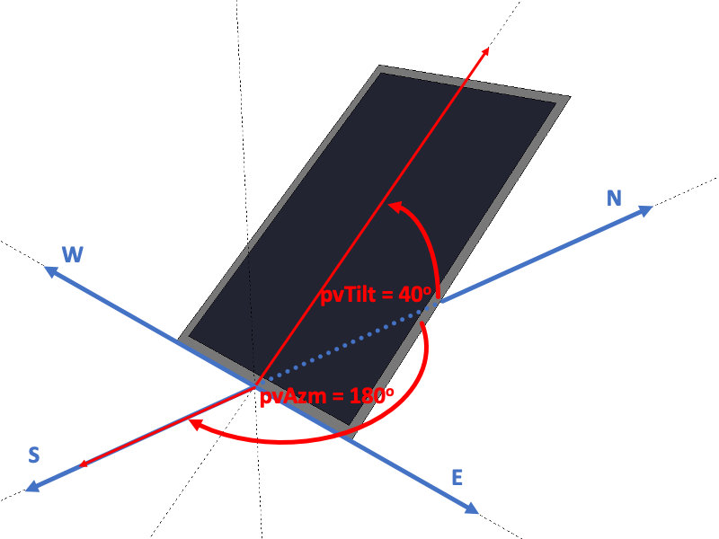
pvAzm=float
Photovoltaic array azimuth (0 = north, 90 = east, etc.). If a value outside the range 0o \(\leq\) x \(<\) 360o is given, it is normalized to that range. For one-axis tracking, defines the azimuth of the rotation axis. Not used for two-axis tracking arrays. Should be omitted if pvVertices is given.
| Units | Legal Range | Default | Required | Variability |
|---|---|---|---|---|
| degrees | unrestricted | from pvVertices (if given) else 0 | No | hourly |
pvVertices=list of up to 36 floats
Vertices of an optional polygon representing the position and shape of the photovoltaic array. The polygon is used to calculate the shaded fraction using an advanced shading model. Only PVARRAYs and SHADEXs are considered in the advanced shading model – PVARRAYs can be shaded by SHADEXs or other PVARRAYs. If pvVertices is omitted, the PVARRAY is assumed to be unshaded at all times. Advanced shading must be enabled via TOP exShadeModel. Note that the polygon is used only for evaluating shading; array capacity is specified by pvDCSysSize (above).
The values that follow pvVertices are a series of X, Y, and Z values for the vertices of the polygon using a coordinate system defined from a viewpoint facing north. X and Y values convey east-west and north-south location respectively relative to an arbitrary origin (positive X value are to the east; positive Y values are to the north). Z values convey height relative to the building 0 level and positive values are upward.
The vertices are specified in counter-clockwise order when facing the receiving surface of the PVARRAY. The number of values provided must be a multiple of 3. The defined polygon must be planar and have no crossing edges. When pvMounting=Building, the effective position of the polygon is modified in response to building rotation specified by TOP bldgAzm.
For example, to specify a rectangular photovoltaic array that is 10 x 20 ft, tilted 45 degrees, and facing south –
pvVertices = 0, 0, 15, 20, 0, 15, 20, 7.07, 22.07, 0, 7.07, 22.07| Units | Legal Range | Default | Required | Variability |
|---|---|---|---|---|
| ft | unrestricted | no polygon | 9, 12, 15, 18, 21, 24, 27, 30, 33, or 36 values | constant |
pvSIF=float
Shading Impact Factor (SIF) of the array used to represent the disproportionate impact on array output of partially shaded modules at the sub-array level. This impact is applied to the effective beam irradiance on the array:
\[I_{poa,beam,eff} = \max\left(I_{poa,beam}\cdot\left(1-SIF\cdot f_{sh}\right),0\right)\]
where \(f_{sh}\) is the fraction of the array that is shaded.
Default value is 1.2, which is representative of PV systems with sub-array microinverters or DC power optimizers. For systems without sub-array power electronics, values are closer to 2.0.
| Units | Legal Range | Default | Required | Variability |
|---|---|---|---|---|
| – | x \(\geq\) 1.0 | 1.2 | No | constant |
pvMounting=choice
Specified mounting location of this PVARRAY. pvMounting=Site indicates the array position is not altered by building rotation via TOP bldgAzm, while PVARRAYs with pvMounting=Building are assumed to rotate with the building.
| Units | Legal Range | Default | Required | Variability |
|---|---|---|---|---|
| Building or Site | Building | No | constant |
pvGrndRefl=float
Ground reflectance used for calculating reflected solar incidence on the array.
| Units | Legal Range | Default | Required | Variability |
|---|---|---|---|---|
| 0 \(<\) x \(<\) 1.0 | 0.2 | No | hourly |
pvDCtoACRatio=float
DC-to-AC ratio used to intentionally undersize the AC inverter. This is used to increase energy production in the beginning and end of the day despite the possibility of clipping peak sun hours.
| Units | Legal Range | Default | Required | Variability |
|---|---|---|---|---|
| x > 0.0 | 1.2 | No | constant |
pvInverterEff=float
AC inverter efficiency at rated DC power.
| Units | Legal Range | Default | Required | Variability |
|---|---|---|---|---|
| 0 \(<\) x \(<\) 1.0 | 0.96 | No | constant |
pvSysLosses=float
Fraction of total DC energy lost. The total loss from a system is aggregated from several possible causes as illustrated below:
| Loss Type | Default Assumption |
|---|---|
| Soiling | 0.02 |
| Shading | 0 (handled explicitly) |
| Snow | 0 |
| Mismatch | 0 (shading mismatch handled explicitly [see pvSIF]) |
| Wiring | 0.02 |
| Connections | 0.005 |
| Light-induced degradation | 0.015 |
| Nameplate rating | 0.01 |
| Age | 0.05 (estimated 0.5% degradation over 20 years) |
| Availability | 0.03 |
| Total | 0.14 |
Italic lines indicate differences from PVWatts assumptions.
| Units | Legal Range | Default | Required | Variability |
|---|---|---|---|---|
| 0 \(<\) x \(<\) 1.0 | 0.14 | No | hourly |
endPVARRAY
Optionally indicates the end of the PVARRAY definition. Alternatively, the end of the definition can be indicated by END or by beginning another object.
| Units | Legal Range | Default | Required | Variability |
|---|---|---|---|---|
| none | No | constant |
Related Probes: