1 Introduction
1.1 Greetings
The purpose of this manual is to document the California Simulation Engine computer program, CSE. CSE is an hourly building and HVAC simulation program which calculates annual energy requirements for building space conditioning and lighting. CSE is specifically tailored for use as internal calculation machinery for compliance with the California building standards.
CSE is a batch driven program which reads its input from a text file. It is not intended for direct use by people seeking to demonstrate compliance. Instead, it will be used within a shell program or by technically oriented users. As a result, this manual is aimed at several audiences:
People testing CSE during its development.
Developers of the CSE shell program.
Researchers and standards developers who will use the program to explore possible conservation opportunities.
Each of these groups is highly sophisticated. Therefore this manual generally uses an exhaustive, one-pass approach: while a given topic is being treated, everything about that topic is presented with the emphasis on completeness and accuracy over ease of learning.
Please note that CSE is under development and will be for many more months. Things will change and from time to time this manual may be inconsistent with the program.
1.2 Manual Organization
This Introduction covers general matters, including program installation.
Operation documents the operational aspects of CSE, such as command line switches, file naming conventions, and how CSE finds files it needs.
Input Structure documents the CSE input language in general.
Input Data describes all of the specific input language statements.
Output Reports will describe the output reports.
Lastly, Probe Definitions lists all available probes.
1.3 Installation
1.3.1 Hardware and Software Requirements
CSE is a 32-bit Microsoft Windows console application. That is, it runs at the command prompt on Windows Vista, Windows 7, Windows 8, and Windows 10. Memory and disk space requirements depend on the size of projects being modeled, but are generally modest.
To prepare input files, a text editor is required. Notepad will suffice, although a text editor intended for programming is generally more capable. Alternatively, some word processors can be used in “ASCII” or “text” or “non-document” mode.
1.3.2 Installation Procedure
Create a directory on your hard disk with the name \CSE or some other name of your choice. Copy the files into that directory. Add the name of the directory to the PATH environment setting unless you intend to use CSE only from the CSE directory.
2 Operation
2.1 Command Line
CSE is invoked from the command prompt or from a batch file using the following command:
CSE *inputfile* {*switches*}where:
- inputfile
- specifies the name of the text input file for the run(s). If the filename has an extension other than “.cse” (the default), it must be included. The name of the file with weather data for the simulation(s) is given in this file (wfName= statement, see Weather Data Items).
- {switches}
- indicates zero or more of the following:
-Dname defines the preprocessor symbol name with the value “”. Useful for testing with
#ifdef name, to invoke variations in the simulation without changing the input file. The CSE preprocessor is described “The Preprocessor”.-Dname=value defines the preprocessor symbol name with the specified value. Name can then be used in the input file to allow varying the simulation without changing the input file – see “The Preprocessor” for more information. The entire switch should be enclosed in quotes if it contains any spaces – otherwise the command processor will divide it into two arguments and CSE will not understand it.
-Uname undefines the preprocessor symbol name.
-ipath;path;path specifies directories where CSE looks for input and include files.
-b batch mode: suppresses all prompts for user input. Currently there are no prompts implemented in CSE. -b is retained in case prompts are added in the future. It is good practice to include -b in batch script CSE invocations.
-n suppresses screen display of warning messages. When -n is specified, warning messages are reported only to the error file.
-p display all the class and member names that can be “probed” or accessed in CSE expressions. “Probes” are described in “Probes”. Use with command processor redirection operator “>” to obtain a report in a file. Inputfile may be given or omitted when -p is given.
-p1 similar to -p, but displays additional member names that cannot be probed or would not make sense to probe in an input file (development aid).
-c display all input names.
-c1 display input names with build-independent details from CSE CULT tables (development aid).
-c2 display input names with all details from CSE CULT tables (development aid).
-x specifies report test prefix; see TOP repTestPfx. The -x command line setting takes precedence over the input file value, if any.
-tnn specifies internal testing option bits (development aid). The following values should be combined bit-wise to determine nn.
1: Omit directory paths from file names in reports, yielding location-independent report files suitable for text comparison.
2: Include detailed timing information in the log file (default is summary only).
2.2 Locating Files
As with any program, in order to invoke CSE, the directory containing CSE.EXE must be the current directory, or that directory must be on the operating system path, or you must type the directory path before CSE.
A CSE simulation requires a weather file. The name of the weather file is given in the CSE input file (wfName= statement, see Weather Data Items). The weather file must be in one of the same three places: current directory, directory containing CSE.EXE, or a directory on the operating system path; or, the directory path to the file must be given in the wfName= statement in the usual pathName syntax. ?? Appears that file must be in current directory due to file locating bugs 2011-07
The CSE input file, named on the CSE command line, must be in the current directory or the directory path to it must be included in the command line.
Included input files, named in #include preprocessor directives (see “The Preprocessor”) in the input file, must be in the current directory or the path to them must be given in the #include directive. In particular, CSE will NOT automatically look for included files in the directory containing the input file. The default extension for included files is “.CSE”.
Output files created by default by CSE (error message file, primary report and export files) will be in the same directory as the input file; output files created by explicit command in the input file (additional report and/or export files) will be in the current directory unless another path is explicitly specified in the command creating the file.
2.3 Output File Names
If any error or warning messages are generated, CSE puts them in a file with the same name and path as the input file and extension .ERR, as well as on the screen and, usually, in the primary (default) report file. The exception is errors in the command line: these appear only on the screen. If there are no error or warning messages, any prior file with this name is deleted.
By default, CSE generates an output report file with the same name and path as the input file, and extension “.REP”. This file may be examined with a text editor and/or copied to an ASCII printer. If any exports are specified, they go by default into a file with the same name and path as the input file and extension “.EXP”.
In response to specifications in the input file, CSE can also generate additional report and export files with user-specified names. The default extensions for these are .REP and .CSV respectively and the default directory is the current directory; other paths and extensions may be specified. For more information on report and export files, see REPORTFILE and EXPORTFILE in “Input Data”.
2.4 Errorlevel
CSE sets the command processor ERRORLEVEL to 2 if any error occurs in the session. This should be tested in batch files that invoke CSE, to prevent use of the output reports if the run was not satisfactory. The ERRORLEVEL is NOT set if only warning messages that do not suppress or abort the run occur, but such messages DO create the .ERR file.
3 Input Structure
DRAFT: In the following, any text annotated with ?? indicates areas of uncertainty or probable change. As the program and input language develop, these matters will be resolved.
3.1 Introduction
The CSE Input Language is the fundamental interface to the CSE program. The language has been designed with three objectives in mind:
Providing direct access to all program features (including ones included for self-testing), to assist in program development.
Providing a set of parametric and expression evaluation capabilities useful for standards development and program testing.
Providing a means for other programs, such as an interactive user interface, to transmit input data and control data to the program.
Thus, the language is not intended to be used by the average compliance or simulation user. Instead, it will be used during program development for testing purposes and subsequently for highly technical parametric studies, such as those conducted for research and standards development. In all of these situations, power, reproducibility, and thorough input documentation take precedence over user-friendliness.
CSE reads its input from a file. The file may be prepared by the user with a text editor, or generated by some other program.
3.2 Form of the CSE Data
The data used by CSE consists of objects. Each object is of a class, which determines what the object represents. For example, objects of class ZONE represent thermally distinct regions of the building; each thermally distinct region has its own ZONE object. An object’s class determines what data items or members it contains. For instance, a ZONE object contains the zone’s area and volume. In addition, each object can have a name.
The objects are organized in a hierarchy, or tree-like structure. For example, under each ZONE object, there can be SURFACE objects to represent the walls, floors, and ceilings of the ZONE. Under SURFACEs there can be WINDOW objects to represent glazings in the particular wall or roof. SURFACE is said to be a subclass of the class ZONE and WINDOW a subclass of SURFACE; each individual SURFACE is said to be a subobject of its particular ZONE object. Conversely, each individual SURFACE is said to be owned by its zone, and the SURFACE class is said to be owned by the ZONE class.
The hierarchy is rooted in the one top-level object (or just Top). The top level object contains information global to the entire simulation, such as the start and end dates, as well as all of the objects that describe the building to be simulated and the reports to be printed.
Objects and their required data must be specified by the user, except that Top is predefined. This is done with input language statements. Each statement begins an object (specifying its class and object name) or gives a value for a data member of the object being created. Each object is specified with a group of statements that are usually given together, and the objects must be organized according to the hierarchy. For example, SURFACEs must be specified within ZONEs and WINDOWs within SURFACEs. Each SURFACE belongs to (is a subobject of) the ZONE within which it is specified, and each WINDOW is a subobject of its SURFACE.
The entire hierarchy of CSE classes can be represented as follows, using indentation to indicate subclasses:
TODO: review hierarchy
TOP (Top-level class; object of this class supplied automatically by CSE)
    HOLIDAY
    MATERIAL
    CONSTRUCTION
        LAYER
    METER
    DHWMETER
    IZXFER
    DHWDAYUSE
        DHWUSE
    DHWSYS
        DHWHEATER
        DHWTANK
        DHWPUMP
        DHWLOOP
        DHWLOOPPUMP
        DHWLOOPSEG
            DHWLOOPBRANCH
    DHWSOLARSYS
        DHWSOLARCOLLECTOR
    ZONE
        GAIN
        SURFACE
            WINDOW
                SHADE
                SGDIST
            DOOR
    REPORTFILE
    REPORT
    REPORTCOL
    EXPORTFILE
    EXPORT
    EXPORTCOL
3.3 Overview of CSE Input Language
The CSE Input Language consists of commands, each beginning with a particular word and, preferably, ending with a semicolon. Each command is either an action-command, which specifies some action such as starting a simulation run, or a statement, which creates or modifies an object or specifies a value for a member of an object.
3.3.1 Statements – Overview
A statement that creates an object consists basically of the class name followed by your name for the object to be created. (The name can be omitted for most classes; optional modifying clauses will be described later.) For example,
ZONE "north";begins an object of class ZONE; the particular zone will be named “north”. This zone name will appear in reports and error messages, and will be used in other statements that operate on the zone. As well as creating the ZONE, this statement sets CSE to expect statements specifying ZONE data members or ZONE subobjects to follow.
A statement specifying a data member consists of the data member’s name, an = sign, an expression specifying the value, and a terminating semicolon. An expression is a valid combination of operands and operators as detailed later; commonly it is just a number, name, or text enclosed in quotes. For example,
znVol = 100000;specifies that the zone has a volume of 100000 cubic feet. (If the statement occurs outside of the description of a ZONE, an error message occurs.) All of the member names for each class are described in the input data section; most of them begin with an abbreviation of the class name for clarity.
The description of a zone or any object except Top can be terminated with the word “END”; but this is not essential; CSE will assume the ZONE ends when you start another ZONE or any object not a subobject of ZONE, or when you specify a member of a higher level class (Top for ZONE), or give an action-command such as RUN.
Statements are free-form; several can be put on a line, or a single statement can occupy several lines. Indentation according to class hierarchy will help make your input file readable. Spaces may be used freely except in the middle of a word or number. Tab characters may be used. Each statement should end with a semicolon. If the semicolon is omitted and the statement and the following statement are both correctly formed, CSE will figure out your intent anyway. But when there is an error, CSE gives clearer error messages when the statements are delimited with semicolons.
Capitalization generally does not matter in input language statements; we like to capitalize class names to make them stand out. Words that differ only in capitalization are NOT distinct to CSE.
Comments (remarks) may be interspersed with commands. Comments are used to make the input file clearer to humans; they are ignored by CSE. A comment introduced with “//” ends at the end of the line; a comment introduced with “/*” continues past the next “*/”, whether on the same line, next line, or many lines down. Additional input language may follow the */ on the same line.
3.3.2 Nested Objects
The following is a brief CSE input file, annotated with comments intended to exemplify how the input language processor follows the object hierarchy when decoding input describing objects and their subobjects.
    // short example file
                            // initially, the current object is Top.
    wfName = "CZ12RV2.CEC"; // give weather file name, a Top member
    begDay = Jan 1;         // start and ...
    endDay = Dec 31;        // ...end run dates: Top members.

    MATERIAL carpet;        // create object of class MATERIAL
    matThk = .296;          // specify 'matThk' member of MATERIAL 'carpet'
    matCond = 1./24;        // give value of 'matCond' for 'carpet'

    CONSTRUCTION slab140C;  /* create object of class CONSTRUCTION, named
                               slab140C. Terminates MATERIAL, because
                               CONSTRUCTION is not a subclass of material
                               in the hierarchy shown in another section** */
      LAYER                 /* start an unnamed object of class LAYER.
                               Since LAYER is a subclass of CONSTRUCTION,
                               this will be a subobject of slab140C. */
        lrMat = carpet;     /* member of the LAYER. Note use of name of
                               MATERIAL object. */
      // (additional layers would be here)

    METER Elec;             /* create METER named Elec;
                               since METER is a subobject of Top,
                               this ends slab140C and its LAYER. */

    ZONE North;             // start a ZONE named North.  Ends METER.
      znArea = 1000;        // specify data members of ZONE North.
      znVol = 10;           // (you don't have to capitalize these as shown.)
      GAIN NorthLights      /* create GAIN object named NorthLights.
                               Creates a subobject of ZONE North. */
        gnPower = 0.01;     // member of NorthLights -- numeric value
        gnMeter = Elec;     // member of NorthLights -- object name value

      znCAir = 3.5;         /* processor knows that znCAir is a member of ZONE;
                               thus this statement terminates the GAIN
                               subobject & continues ZONE 'North'. */

      /*lrMat = ...            would be an error here, because the current
                               object is not a LAYER nor a subobject of LAYER */

    RUN;                    /* initiate simulation run with data given.
                               Terminates ZONE North, since action-commands
                               terminate all objects being constructed. */
** See Form of the CSE Data
3.3.3 Expressions – Overview
Expressions are the parts of statements that specify values – numeric values, string values, object name values, and choice values. Expressions are composed of operators and operands, in a manner similar to many programming languages. The available operators and operands will be described in the section on operators.
Unlike most programming languages, CSE expressions have Variation. Variation is how often a value changes during the simulation run – hourly, daily, monthly, yearly (i.e. does not change during run), etc. For instance, the operand $hour represents the hour of the day and has “hourly” variation. An expression has the variation of its fastest-varying component.
Each data member of each object (and every context in which an expression may be used) has its allowed variability, which is the fastest variation it will accept. Many members allow no variability. For example, begDay, the date on which the run starts, cannot meaningfully change during the run. On the other hand, a thermostat setting can change hourly. Thermostat settings and other scheduled values are specified in CSE with expressions that often make use of variability; there is no explicit SCHEDULE class.
For example, a heating setpoint that was 68 during business hours and 55 at night might be expressed as
select( $hour > 8 && $hour < 18, 68, default 55)An example of a complete statement containing the above expression is:
tuTH = select( $hour > 8 && $hour < 18, 68, default 55);The preceding is valid a statement if used in a TERMINAL description. The following:
begDay = select( $hour > 8 && $hour < 18, 68, default 55);would always get an error message, because begDay (the starting day of the run) will not accept hourly variation, and the expression varies hourly, since it contains $hour. The expression’s variation is considered “hourly” even though it changes only twice a day, since CSE has no variation category between hourly and daily.
CSE’s expression capability may be used freely to make input clearer. For example,
znVol = 15 * 25 * 8;meaning that the zone volume is 15 times 25 times 8 is the same to CSE as
znVol = 3000;but might be useful to you to tersely indicate that the volume resulted from a width of 15, a length of 25, and a height of 8. Further, if you wished to change the ceiling height to 9 feet, the edit would be very simple and CSE would perform the volume calculation for you.
CSE computes expressions only as often as necessary, for maximum simulation speed. For example,
tuTH = 68;causes 68 to be stored in the heating setpoint once at the start of the run only, even though tuTH will accept expressions with variability up to hourly. Furthermore, constant inner portions of variable expressions are pre-evaluated before the run begins.
CSE statements and expressions do not (yet) have user-settable variables in the usual programming language sense. They do, however, have user-defined functions to facilitate using the same computation several places, and preprocessor macros, to facilitate using the same text several places, specifying parametric values in a separate file, etc.
3.3.4 The Preprocessor – Overview
The preprocessor scans and processes input file text before the language processor sees the text. The preprocessor can include (embed) additional files in the input, include sections of input conditionally, and define and expand macros.
Macros are a mechanism to substitute a specified text for each occurrence of a word (the macro name). For example,
    #define ZNWID 20
    #define ZNLEN 30
    . . .

    znArea = ZNWID * ZNLEN;
    znVol  = ZNWID * ZNLEN * 8;
The first line above says that all following occurrences of “ZNWID” are to be replaced with “20” (or whatever follows ZNWID on the same line). The effect of the above is that the zone width and length are specified only one place; if the single numbers are editing, both the zone area and zone volume change to match.
Macros can be especially powerful when combined with the file inclusion feature; the generic building description could be in one file, and the specific values for multiple runs supplied by another file. By also using conditional compilation, the values-specifying file can select from a range of features available in the building description file.
The preprocessor is similar to that of the C programming language, and thus will be familiar to C programmers.
The next section describes the preprocessor in detail. The preprocessor description is followed by sections detailing statements, then expressions.
3.4 The Preprocessor
Note: The organization and wording of this section is based on section A12 of Kernigan and Richie [1988]. The reader is referred to that source for a somewhat more rigorous presentation but with the caution that the CSE input language preprocessor does not completely comply to ANSI C specifications.
The preprocessor performs macro definition and expansion, file inclusion, and conditional inclusion/exclusion of text. Lines whose first non-whitespace character is # communicate with the preprocessor and are designated preprocessor directives. Line boundaries are significant to the preprocessor (in contrast to the rest of the input language in which a newline is simply whitespace), although adjacent lines can be spliced with \, as discussed below. The syntax of preprocessor directives is separate from that of the rest of the language. Preprocessor directives can appear anywhere in an input file and their effects last until the end of the input file. The directives that are supported by the input language preprocessor are the following:
    #if
    #else
    #elif
    #endif
    #ifndef

    #define
    #redefine
    #undef

    #include
3.4.1 Line splicing
If the last character on a line is the backslash \, then the next line is spliced to that line by elimination of the backslash and the following newline. Line splicing occurs before the line is divided into tokens.
Line splicing finds its main use in defining long macros:
    // hourly light gain values:
    #define LIGHT_GAIN       .024, .022, .021, .021, .021, .026, \
                             .038, .059, .056, .060, .059, .046, \
                             .045, .5  , .5  , .05 , .057, .064, \
                             .064, .052, .050, .055, .044, .027
3.4.2 Macro definition and expansion
A directive of the form
#define _identifier_ _token-sequence_is a macro definition and causes the preprocessor to replace subsequent instances of the identifier with the given token sequence. Note that the token string can be empty (e.g. #define FLAG).
A line of the form
#define _identifier_( _identifier-list_) _token-sequence_where there is no space between the identifier and the (, is a macro with parameters given by the identifier list. The expansion of macros with parameters is discussed below.
Macros may also be defined on the CSE command line, making it possible to vary a run without changing the input files at all. As described in the command line section, macros are defined on the CSE command line using the -D switch in the forms
    -D_identifier_

    -D_identifier_=_token-sequence_
The first form simply defines the name with no token-sequence; this is convenient for testing with #ifdef, #ifndef, or defined(), as described in the section on conditional inclusion of tex. The second form allows an argument list and token sequence. The entire command line argument must be enclosed in quotes if it contains any spaces.
A macro definition is forgotten when an #undef directive is encountered:
#undef _identifier_It is not an error to #undef an undefined identifier.
A macro may be re-#defined without a prior #undef unless the second definition is identical to the first. A combined #undef/#define directive is available to handle this common case:
    #redefine _identifier_ _token-sequence_

    #redefine _identifier_( _identifier-list_) _token-sequence_
When a macro is #redefined, it need not agree in form with the prior definition (that is, one can have parameters even if the other does not). It is not an error to #redefine an undefined identifier.
Macros defined in the second form (with parameters) are expanded whenever the preprocessor encounters the macro identifier followed by optional whitespace and a comma-separated parameter list enclosed in parentheses. First the comma separated token sequences are collected; any commas within quotes or nested parentheses do not separate parameters. Then each unquoted instance of the each parameter identifier in the macro definition is replaced by the collected tokens. The resulting string is then repeatedly re-scanned for more defined identifiers. The macro definition and reference must have the same number of arguments.
It is often important to include parentheses within macro definitions to make sure they evaluate properly in all situations. Suppose we define a handy area macro as follows:
#define AREA(w, h) w*h // WRONGConsider what happens when this macro is expanded with arguments 2+3 and 4+1. The preprocessor substitutes the arguments for the parameters, then the input language processor processes the statement containing the macro expansion without regard to the beginning and end of the arguments. The expected result is 25, but as defined, the macro will produce a result of 15. Parentheses fix it:
#define AREA(w, h) ((w)*(h)) // RIGHTThe outer enclosing set of parentheses are not strictly needed in our example, but are good practice to avoid evaluation errors when the macro expands within a larger expression.
Note 1: The CSE preprocessor does not support the ANSI C stringizing (#) or concatenation (##) operators.
Note 2: Identifiers are case insensitive (unlike ANSI C). For example, the text “myHeight” will be replaced by the #defined value of MYHEIGHT (if there is one).
The preprocessor examples at the end of this section illustrate macro definition and expansion.
3.4.3 File inclusion
Directives of the form
#include "filename" and
#include <filename>
cause the replacement of the directive line with the entire contents of the referenced file. If the filename does not include an extension, a default extension of .INP is assumed. The filename may include path information; if it does not, the file must be in the current directory.
#includes may be nested to a depth of 5.
For an example of the use #includes, please see the preprocessor examples at the end of this section.
3.4.4 Conditional inclusion of text
Conditional text inclusion provides a facility for selectively including or excluding groups of input file lines. The lines so included or excluded may be either CSE input language text or other preprocessor directives. The latter capability is very powerful.
Several conditional inclusion directive involve integer constant expressions. Constant integer expressions are formed according the rules discussed in the section on expressions with the following changes:
Only constant integer operands are allowed.
All values (including intermediate values computed during expression evaluation) must remain in the 16 bit range (-32768 - 32767). The expression processor treats all integers as signed values and requires signed decimal constants – however, it requires unsigned octal and hexadecimal constants. Thus decimal constants must be in the range -32768 - 32767, octal must be in the range 0 - 0o177777, and hexadecimal in the range 0 - 0xffff. Since all arithmetic comparisons are done assuming signed values, 0xffff < 1 is true (unhappily). Care is required when using the arithmetic comparison operators (<, <=, >=, >).
The logical relational operators && and || are not available. Nearly equivalent function can be obtained with & and |.
A special operand defined( ) is provided; it is described below.
Macro expansion is performed on constant expression text, so symbolic expressions can be used (see examples below).
The basic conditional format uses the directive
#if _constant-expression_If the constant expression has the value 0, all lines following the #if are dropped from the input stream (the preprocessor discards them) until a matching #else, #elif, or #endif directive is encountered.
The defined( identifier ) operand returns 1 if the identifier is the name of a defined macro, otherwise 0. Thus
#if defined( _identifier_ )can be used to control text inclusion based on macro flags. Two #if variants that test whether a macro is defined are also available. #ifdef identifier is equivalent to #if defined(identifier) and #ifndef identifier is equivalent to #if !defined(identifier).
Defined(), #ifdef, and #ifndef consider a macro name “defined” even if the body of its definition contains no characters; thus a macro to be tested with one of these can be defined with just
#define _identifier_or with just “-Didentifier” on the CSE command line.
Conditional blocks are most simply terminated with #endif, but #else and #elif constant-expression are also available for selecting one of two or more alternative text blocks.
The simplest use of #if is to “turn off” sections of an input file without editing them out:
    #if 0
    This text is deleted from the input stream.
    #endif
Or, portions of the input file can be conditionally selected:
    #define FLRAREA 1000   // other values used in other runs
    #if FLRAREA <= 800
        CSE input language for small zones
    #elif FLRAREA <= 1500
        CSE input language for medium zones
    #else
        CSE input language for large zones
    #endif
Note that if a set of #if … #elif … #elif conditionals does not contain an #else, it is possible for all lines to be excluded.
Finally, it is once again important to note that conditional directives nest, as shown in the following example (indentation is included for clarity only):
    #if 0
        This text is NOT included.
        #if 1
            This text is NOT included.
        #endif
    #else
        This text IS included.
    #endif
3.4.5 Input echo control
By default, CSE echos all input text to the input echo report (see REPORT rpType=INP). #echooff and #echoon allow disabling and re-enabling text echoing. This capability is useful reducing report file size by suppressing echo of, for example, large standard include files.
    ... some input ...   // text sent to the input echo report
    #echooff
       // This text will NOT be sent to the input echo report.
       // However, it IS read and used by CSE.
       // Error messages will be echoed even if #echooff
       ... more input ...
    #echoon         // restore echo
Nesting is supported – each #echoon “undoes” the prior #echooff, but echoing does not resume until the topmost (earliest) #echooff is cancelled. * #echoon has no effect when echoing is already active. * Unmatched #echooffs are ignored – echoing remains disabled through the end of the input stream.
3.4.6 Preprocessor examples
This section shows a few combined examples that demonstrate the preprocessor’s capabilities.
The simplest use of macros is for run parameterization. For example, a base file is constructed that derives values from a macro named FLRAREA. Then multiple runs can be performed using #include:
    // Base file
    ... various input language statements ...

    ZONE main
        znArea = FLRAREA
        znVol  = 8*FLRAREA
        znCAir = 2*FLRAREA ...
        ... various other input language statements ...

    RUN

    CLEAR
The actual input file would look like this:
    // Run with zone area = 500, 1000, and 2000 ft2
    #define FLRAREA 500
    #include "base."
    #redefine FLRAREA 1000
    #include "base."
    #redefine FLRAREA 2000
    #include "base."
Macros are also useful for encapsulating standard calculations. For example, most U-values must be entered without surface conductances, yet many tabulated U-values include the effects of the standard ASHRAE winter surface conductance of 6.00 Btuh/ft2-oF. A simple macro is very helpful:
#define UWinter(u) ( 1/(1/(u)-1/6.00) )This macro can be used whenever a U-value is required (e.g. SURFACE … sfU=UWinter(.11) … ).
3.5 CSE Input Language Statements
This section describes the general form of CSE input language statements that define objects, assign values to the data members of objects, and initiate actions. The concepts of objects and the class hierarchy were introduced in the section on form of CSE data. Information on statements for specific CSE input language classes and their members is the subject of the input data section.
3.5.1 Object Statements
As we described in a previous section, the description of an object is introduced by a statement containing at least the class name, and usually your chosen name for the particular object. In addition, this section will describe several optional qualifiers and modifying clauses that permit defining similar objects without repeating all of the member details, and reopening a previously given object description to change or add to it.
Examples of the basic object-beginning statement:
    ZONE "North";

    METER "Electric - Cooling";

    LAYER;
As described in the section on nested objects, such a statement is followed by statements giving the object’s member values or describing subobjects of the object. The object description ends when you begin another object that is not of a subclass of the object, or when a member of an embedding (higher level) object previously begun is given, or when END is given.
3.5.1.1 Object Names
An object name consists of up to 63 characters. If you always enclose the name in quotation marks, punctuation and spaces may be used freely; if the name starts with a letter or dollar sign and consists only of letters, digits, underscore, and dollar sign, and is different from all of the words already defined in CSE input language (as listed below in this section), you may omit the quotes. Capitalization, and Leading and trailing spaces and tabs, are always disregarded by input language processor. Names of 0 length, and names containing control characters (ASCII codes 0-31) are not allowed.
Examples of valid names that do not require quotes:
    North
    gas_meter
    slab140E
The following object names are acceptable if always enclosed in quotes:
    "Front Door"
    "M L King Day"
    "123"
    "3.5-inch wall"
We suggest always quoting object names so you won’t have to worry about disallowed words and characters.
Duplicate names result in error messages. Object names must be distinct between objects of the same class which are subobjects of the same object. For example, all ZONE names must be distinct, since all ZONEs are subobjects of Top. It is permissible to have SURFACEs with the same name in different ZONEs – but it is a good idea to keep all of your object names distinct to minimize the chance of an accidental mismatch or a confusing message regarding some other error.
For some classes, such as ZONE, a name is required for each object. This is because several other statements refer to specific ZONEs, and because a name is needed to identify ZONEs in reports. For other classes, the name is optional. The specific statement descriptions in the Input Data Section 5 say which names are required. We suggest always using object names even where not required; one reason is because they allow CSE to issue clearer error messages.
The following reserved words will not work as object names unless enclosed in quotes:
(this list needs to be assembled and typed in)
3.5.1.2 ALTER
ALTER is used to reopen a previously defined object when it is not possible or desired to give the entire description contiguously.
ALTER could be used if you wish to order the input in a special way. For example, SURFACE objects are subobjects of ZONE and are normally described with the ZONE they are part of. However, if you wanted to put all roofs together, you could use input of the general form:
    ZONE "1";  . . .  (zone 1 description)
    ZONE "2";  . . .
    . . .
    ALTER ZONE "1";               // revert to specifying zone 1
        SURFACE "Roof1";  . . .   (describe roof of zone 1)
    ALTER ZONE "2";
        SURFACE "Roof2";  . . .
ALTER can be used to facilitate making similar runs. For example, to evaluate the effect of a change in the size of a window, you might use:
    ZONE "South";
        SURFACE "SouthWall";
        ...
            WINDOW "BigWindow";
                wnHeight = 6;  wnWidth = 20;
    . . .
    RUN;          // perform simulation and generate reports
    // data from simulation is still present unless CLEAR given
    ALTER ZONE "South";
        ALTER SURFACE "SouthWall";
            ALTER WINDOW "BigWindow";
                wnHeight = 4;  wnWidth = 12;  // make window smaller
    RUN;          // perform simulation and print reports again
ALTER also lets you access the predefined “Primary” REPORTFILE and EXPORTFILE objects which will be described in the Input Data Section:
    ALTER REPORTFILE "Primary";    /* open description of object automatically
                                      supplied by CSE -- no other way to access */
        rfPageFmt = NO;            /* Turn off page headers and footers --
                                      not desired when reports are to be
                                      reviewed on screen. */
3.5.1.3 DELETE
DELETE followed by a class name and an object name removes the specified object, and any subobjects it has. You might do this after RUN when changing the data for a similar run (but to remove all data, CLEAR is handier), or you might use DELETE after COPYing (below) an object if the intent is to copy all but certain subobjects.
3.5.1.4 LIKE clause
LIKE lets you specify that an object being defined starts with the same member values as another object already defined. You then need give only those members that are different. For Example:
    MATERIAL "SheetRock";         // half inch gypsum board
        matCond = .0925;          // conductivity per foot
        matSpHt = .26;            // specific heat
        matDens = 50;             // density
        matThk = 0'0.5;           // thickness 1/2 inch
    MATERIAL "5/8 SheetRock" LIKE "SheetRock"; // 5/8" gypsum board
        matThk = 0'0.625;         // thickness 5/8 inch
        // other members same as "SheetRock", need not be repeated
The object named after LIKE must be already defined and must be of the same class as the new object.
LIKE copies only the member values; it does not copy any subobjects of the prototype object. For example, LIKEing a ZONE to a previously defined ZONE does not cause the new zone to contain the surfaces of the prototype ZONE. If you want to duplicate the surfaces, use COPY instead of LIKE.
3.5.1.5 COPY clause
COPY lets you specify that the object being defined is the same as a previously defined object including all of the subobjects of that object. For example,
    . . .
    ZONE "West" COPY "North";
        DELETE WALL "East";
        ALTER WALL "South";
            sfExCnd = ambient;
Specifies a ZONE named “West” which is the same as ZONE North except that it does not contain a copy of West’s East wall, and the South wall has ambient exposure.
3.5.1.6 USETYPE clause
USETYPE followed by the type name is used in creating an object of a type previously defined with DEFTYPE (next section). Example:
    SURFACE "EastWall" USETYPE "IntWall";     // use interior wall TYPE (below)
        sfAzm = 90;                           // this wall faces to the East
        sfArea = 8 * 30;                      // area of each wall is different
        sfAdjZn = "East";                     // zone on other side of wall
Any differences from the type, and any required information not given in the type, must then be specified. Any member specified in the type may be respecified in the object unless FROZEN (see this section) in the type (normally, a duplicate specification for a member results in an error message).
3.5.1.7 DEFTYPE
DEFTYPE is used to begin defining a TYPE for a class. When a TYPE is created, no object is created; rather, a partial or complete object description is stored for later use with DEFTYPE. TYPES facilitate creating multiple similar objects, as well as storing commonly used descriptions in a file to be #included in several different files, or to be altered for multiple runs in comparative studies without changing the including files. Example (boldface for emphasis only):
    DEFTYPE SURFACE "BaseWall"                // common characteristics of all walls
        sfType = WALL;                        // walls are walls, so say it once
        sfTilt = 90;                          // all our walls are vertical;
                                              //  but sfAzm varies, so it is not in TYPE.
        sfU = .83;                            // surf conductance; override if different
        sfModel = QUICK;

    DEFTYPE SURFACE "ExtWall" USETYPE "BaseWall";
        sfExCnd = AMBIENT;                    // other side of wall is outdoors
        sfExAbs = 0.5;                        // member only needed for exterior walls

    DEFTYPE SURFACE "IntWall" USETYPE "BaseWall";   // interior wall
        sfExCnd = ADJZN;                      // user must give sfAdjZn.
In a TYPE as much or as little of the description as desired may be given. Omitting normally-required members does not result in an error message in the type definition, though of course an error will occur at use if the member is not given there.
At use, member values specified in the TYPE can normally be re specified freely; to prevent this, “freeze” the desired member(s) in the type definition with
FREEZE *memberName*;Alternately, if you wish to be sure the user of the TYPE enters a particular member even if it is normally optional, use
REQUIRE *memberName*Sometimes in the TYPE definition, member(s) that you do not want defined are defined – for example, if the TYPE definition were itself initiated with a statement containing LIKE, COPY, or USETYPE. In such cases the member specification can be removed with
UNSET *memberName*;3.5.1.8 END and ENDxxxx
END, optionally followed by an object name, can be used to unequivocally terminate an object. Further, as of July 1992 there is still available a specific word to terminate each type of object, such as ENDZONE to terminate a ZONE object. If the object name is given after END or ENDxxxx, an additional check is performed: if the name is not that of an object which has been begun and not terminated, an error message occurs. Generally, we have found it is not important to use END or ENDxxxx, especially since the member names in different classes are distinct.
3.5.2 Member Statements
As introduced in the section on statements, statements which assign values to members are of the general form:
*memberName* = *expression*;The specific member names for each class of objects are given in Section 5; many have already been shown in examples.
Depending on the member, the appropriate type for the expression giving the member value may be numeric (integer or floating point), string, object name, or multiple-choice. Expressions of all types will be described in detail in the section on expressions.
Each member also has its variability (also given in the input data section), or maximum acceptable variation. This is how often the expression for the value can change during the simulation – hourly, daily, monthly, no change (constant), etc. The “variations” were introduced in the expressions overview section and will be further detailed in a section on variation frequencies.
Four special statements, AUTOSIZE, UNSET, REQUIRE, and FREEZE, add flexibility in working with members.
3.5.2.1 AUTOSIZE
AUTOSIZE followed by a member name, sets the member to be sized by CSE. The option to AUTOSIZE a member will be shown under its legal range where it is described in the input data section. AUTOSIZE is only applicable to members describing HVAC system airflows and heating/cooling capacities. If AUTOSIZE is used for any member in the input, input describing design day conditions must also be specified (see TOP Autosizing).
3.5.2.2 UNSET
UNSET followed by a member name is used when it is desired to delete a member value previously given. UNSETing a member resets the object to the same internal state it was in before the member was originally given. This makes it legal to specify a new value for the member (normally, a duplicate specification results in an error message); if the member is required (as specified in the input data section), then an error message will occur if RUN is given without re specifying the member.
Situations where you really might want to specify a member, then later remove it, include:
After a RUN command has completed one simulation run, if you wish to specify another simulation run without CLEARing and giving all the data again, you may need to UNSET some members of some objects in order to re specify them or because they need to be omitted from the new run. In this case, use ALTER(s) to reopen the object(s) before UNSETing.
In defining a TYPE (see this section), you may wish to make sure certain members are not specified so that the user must give them or omit them if desired. If the origin of the type (possibly a sequence of DEFTYPEs, LIKEs, and/or COPYs) has defined unwanted members, get rid of them with UNSET.
Note that UNSET is only for deleting members (names that would be followed with an = and a a value when being defined). To delete an entire object, use DELETE (see this section).
3.5.2.3 REQUIRE
REQUIRE followed by a member name makes entry of that member mandatory if it was otherwise optional; it is useful in defining a TYPE (see this section) when you desire to make sure the user enters a particular member, for example to be sure the TYPE is applied in the intended manner. REQUIRE by itself does not delete any previously entered value, so if the member already has a value, you will need to UNSET it. ?? verify
3.5.2.4 FREEZE
FREEZE followed by a member name makes it illegal to UNSET or redefine that member of the object. Note that FREEZE is unnecessary most of the time since CSE issues an error message for duplicate definitions without an intervening UNSET, unless the original definition came from a TYPE (see this section). Situations where you might want to FREEZE one or more members include:
When defining a TYPE (see this section). Normally, the member values in a type are like defaults; they can be freely overridden by member specifications at each use. If you wish to insure a TYPE is used as intended, you may wish to FREEZE members to prevent accidental misuse.
When your are defining objects for later use or for somebody else to use (perhaps in a file to be included) and you wish to guard against misuse, you may wish to FREEZE members. Of course, this is not foolproof, since there is at present no way to allow use of predefined objects or types without allowing access to the statements defining them.
3.5.3 Action Commands
CSE has two action commands, RUN and CLEAR.
3.5.3.1 RUN
RUN tells CSE to do an hourly simulation with the data now in memory, that is, the data given in the preceding part of the input file.
Note that CSE does NOT automatically run the simulator; an input file containing no RUN results in no simulation (you might nevertheless wish to submit an incomplete file to CSE to check for errors in the data already entered). The explicit RUN command also makes it possible to do multiple simulation runs in one session using a single input file.
When RUN is encountered in the input file, CSE checks the data. Many error messages involving inconsistencies between member values or missing required members occur at this time. If the data is good, CSE starts the simulation. When the simulation is complete and the reports have been output, CSE continues reading the input file. Statements after the first run can add to or change the data in preparation for another RUN. Note that the data for the first run is NOT automatically removed; if you wish to start over with complete specifications, use CLEAR after RUN.
3.5.3.2 CLEAR
CLEAR removes all input data (objects and all their members) from CSE memory. CLEAR is normally used after RUN, when you wish to perform another simulation run and wish to start clean. If CLEAR is not used, the objects from the prior run’s input remain in memory and may be changed or added to produce the input data for the next simulation run.
3.6 Expressions
Probably the CSE input language’s most powerful characteristic is its ability to accept expressions anywhere a single number, string, object name, or other value would be accepted. Preceding examples have shown the inputting zone areas and volumes as numbers (some defined via preprocessor macros) with *’s between them to signify multiplication, to facilitate changes and avoid errors that might occur in manual arithmetic. Such expressions, where all operands are constants, are acceptable anywhere a constant of the same type would be allowed.
But for many object members, CSE accepts live expressions that vary according to time of day, weather, zone temperatures, etc. (etc., etc., etc.!). Live expressions permit simulation of many relationships without special-purpose features in the language. Live expressions support controlling setpoints, scheduling HVAC system operation, resetting air handler supply temperature according to outdoor temperature, and other necessary and foreseen functions without dedicated language features; they will also support many unforeseen user-generated functionalities that would otherwise be unavailable.
Additional expression flexibility is provided by the ability to access all of the input data and much of the internal data as operands in expressions (probes, see this section).
As in a programming language, CSE expressions are constructed from operators and operands; unlike most programming languages, CSE determines how often an expression’s operands change and automatically compute and store the value as often as necessary.
Expressions in which all operands are known when the statement is being decoded (for example, if all values are constants) are always allowed, because the input language processor immediately evaluates them and presents the value to the rest of the program in the same manner as if a single number had been entered. Most members also accept expressions that can be evaluated as soon as the run’s input is complete, for example expressions involving a reference to another member that has not been given yet. Expressions that vary during the run, say at hourly or daily intervals, are accepted by many members. The variability or maximum acceptable variation for each member is given in the descriptions in the input data section, and the variation of each non-constant expression component is given in its description in this section.
Interaction of expressions and the preprocessor: Generally, they don’t interact. The preprocessor is a text processor which completes its work by including specified files, deleting sections under false #if’s, remembering define definitions, replacing macro calls with the text of the definition, removing preprocessor directives from the text after interpreting them, etc., then the resulting character stream is analyzed by the input language statement compiler. However, the if statement takes an integer numeric expression argument. This expression is similar to those described here except that it can only use constant operands, since the preprocessor must evaluate it before deciding what text to feed to the input statement statement compiler.
3.6.1 Expression Types
The type of value to which an expression must evaluate is specified in each member description (see the input data section) or other context in which an expression can be used. Each expression may be a single constant or may be made up of operators and operands described in the rest of this section, so long as the result is the required type or can be converted to that type by CSE, and its variation is not too great for the context. The possible types are:
| float | A real number (3.0, 5.34, -2., etc.). Approximately 7 digits are carried internally. If an int is given where a real is required, it is automatically converted. |
| int | An integer or whole number (-1, 0, 1, 2 etc.). If a real is given, an error may result, but we should change it to convert it (discarding any fractional part). |
| Boolean | Same as int; indicates that a 0 value will be interpreted as “false” and any non-0 value will be interpreted as “true”. |
| string | A string of characters; for example, some text enclosed in quotes. |
| object name | Name of an object of a specified class. Differs from string in that the name need not be enclosed in quotes if it consists only of letters, digits, _, and $, begins with a non-digit, and is different from all reserved words now in or later added to the language (see Object Names). |
| The object may be defined after it is referred to. An expression using conditional operators, functions, etc. may be used provided its value is known when the RUN action command is reached.; no members requiring object names accept values that vary during the simulation. | |
| choice | One of several choices; a list of the acceptable values is given wherever a choice is required. The choices are usually listed in CAPITALS but may be entered in upper or lower case as desired. As with object names, quotes are allowed but not required. |
| Expressions may be used for choices, subject to the variability of the context. | |
| date | May be entered as a 3-letter month abbreviation followed by an int for the day of the month, or an int for the Julian day of the year (February is assumed to have 28 days). Expressions may be used subject to variability limitations. Examples: |
Jan 23 // January 23 | |
23 // January 23 | |
32 // February 1 |
These words are used in following descriptions of contexts that can accept more than one basic type:
| numeric | float or int. When floats and ints are intermixed with the same operator or function, the result is float. |
| anyType | Any type; the result is the same type as the argument. If floats and ints are intermixed, the result is float. If strings and valid choice names are intermixed, the result is choice. Other mixtures of types are generally illegal, except in expressions for a few members that will accept either one of several choices or a numeric value. |
The next section describes the syntax of constants of the various data types; then, we will describe the available operators, then other operand types such as system variables and built-in functions.
3.6.2 Constants
This section reviews how to enter ordinary non-varying numbers and other values.
| int | optional - sign followed by digits. Don’t use a decimal point if your intent is to give an int quantity – the decimal point indicates a float to CSE. Hexadecimal and Octal values may be given by prefixing the value with 0x and 0O respectively (yes, that really is a zero followed by an ‘O’). |
| float | optional - sign, digits and decimal point. Very large or small values can be entered by following the number with an “e” and a power of ten. Examples; |
1.0 1. .1 -5534.6 123.e25 4.56e-23 | |
| The decimal point indicates a float as opposed to an int. Generally it doesn’t matter as CSE converts ints to floats as required, but be careful when dividing: CSE interprets “2/3” as integer two divided by integer 3, which will produce an integer 0 before CSE notices any need to convert to float. If you mean .6666667, say 2./3, 2/3., or .6666667. | |
| feet and inches | Feet and inches may be entered where a float number of feet is required by typing the feet (or a 0 if none), a single quote ’, then the inches. (Actually this is an operator meaning “divide the following value by 12 and add it to the preceding value”, so expressions can work with it.) Examples: |
3'6 0'.5 (10+20)'(2+3) | |
| string | “Text” – desired characters enclosed in double quotes. Maximum length 80 characters (make 132??). To put a " within the “’s, precede it with a backslash. Certain control codes can be represented with letters preceded with a backslash as follows: |
\\e escape | |
\\t tab | |
\\f form feed | |
\\r carriage return | |
\\n newline or line feed | |
| object name | Same as string, or without quotes if name consists only of letters, digits, _, and $, begins with a non-digit, and is different from all reserved words now in or later added to the language (see Object Names). Control character codes (ASCII 0-31) are not allowed. |
| choice | Same as string; quotes optional on choice words valid for the member. Capitalization does not matter. |
| date | Julian day of year (as int constant), or month abbreviation |
Jan Feb Mar Apr May Jun Jul Aug Sep Oct Nov De c | |
| followed by the int day of month. (Actually, the month names are operators implemented to add the starting day of the month to the following int quantity). |
3.6.3 Operators
For floats and ints, the CSE input language recognizes a set of operators based closely on those found in the C programming language. The following table describes the available numeric operators. The operators are shown in the order of execution (precedence) when no ()’s are used to control the order of evaluation; thin lines separate operators of equal precedence.
| Operator | Name | Notes and Examples |
|---|---|---|
| ’ | Feet-Inches Separator | a ’ b yields a + b/12; thus 4’6 = 4.5. |
| + | Unary plus | The familiar “positive”, as in +3. Does nothing; rarely used. |
| - | Unary minus | The familiar “minus”, as in -3. -(-3) = +3 etc. |
| ! | Logical NOT | Changes 0 to 1 and any non-0 value to 0. !0 = 1, !17 = 0. |
| ~ | One’s complement | Complements each bit in an int value. |
| * | Multiplication | Multiplication, e.g. 3*4 = 12; 3.24*18.54 = 60.07 |
| / | Division | Division, e.g. 4/2 = 2, 3.24/1.42 = 2.28. Integer division truncates toward 0 (e.g. 3/2 = 1, 3/-2 = -1, -3/2 = -1, 2/3 = 0) CAUTION! |
| % | Modulus | Yields the remainder after division, e.g. 7%2 = 1. The result has the same sign as the left operand (e.g.(-7)%2 = -1). % is defined for both integer and floating point operands (unlike ANSI C). |
| + | Addition | Yields the sum of the operands, e.g. 5+3 = 8 |
| - | Subtraction | Yields the difference of the operands, e.g. 5-3 = 2 |
| >> | Right shift | a >> b yields a shifted right b bit positions, e.g. 8>>2 = 2 |
| << | Left shift | a << b yields a shifted left b bit positions, e.g. 8<<2 = 32 |
| < | Less than | a < b yields 1 if a is less than b, otherwise 0 |
| <= | Less than or equal | a <= b yields 1 if a is less than or equal to b, otherwise 0 |
| >= | Greater than or equal | a >= b yields 1 if a is greater than or equal to b, otherwise 0 |
| > | Greater than | a > b yields 1 if a is greater than b, otherwise 0 |
| == | Equal | a == b yields 1 if a is exactly (bit wise) equal to b, otherwise 0 |
| != | Not equal | a != b yields 1 if a is not equal to b, otherwise 0 |
| & | Bitwise and | a & b yields the bitwise AND of the operands, e.g. 6 & 2 = 2. |
| ^ | Bitwise exclusive or | a ^ b yields the bitwise XOR of the operands, e.g. 6 ^ 2 = 4. |
| | | Bitwise inclusive or | a | b yields the bitwise IOR of the operands, e.g. 6 | 2 = 6. |
| && | Logical AND | a && b yields 1 if both a and b are non-zero, otherwise 0. && guarantees left to right evaluation: if the first operand evaluates to 0, the second operand is not evaluated and the result is 0. |
| || | Logical OR | a || b yields 1 if either a or b is true (non-0), otherwise 0. || guarantees left to right evaluation: if the first operand evaluates to non-zero, the second operand in not evaluated and the result is 1. |
| ? : | Conditional | a ? b : c yields b if a is true (non-0), otherwise c. |
Dates are stored as ints (the value being the Julian day of the year), so all numeric operators could be used. The month abbreviations are implemented as operators that add the first day of the month to the following int value; CSE does not disallow their use in other numeric contexts.
For strings, object names, and choices, the CSE input language currently has no operators except the ?: conditional operator and the concat() function. Note, though, that the choose, choose1, select, and hourval functions described below work with strings, object names, and choice values as well as numbers.
3.6.4 System Variables
System Variables are built-in operands with useful values. To avoid confusion with other words, they begin with a $. Descriptions of the CSE system variables follow. Capitalization shown need not be matched. Most system variables change during a simulation run, resulting in the variations shown; they cannot be used where the context will not accept variation at least this fast. (The Input Data Section gives the variability, or maximum acceptable variation, for each object member.)
| $dayOfYear | Day of year of simulation, 1 - 365; 1 corresponds to Jan-1. (Note that this is not the day of the simulation unless begDay is Jan-1.) Variation: daily. |
| $month | Month of year, 1 - 12. Variation: monthly. |
| $dayOfMonth | Day of month, 1 - 31. Variation: daily. |
| $hour | Hour of day, 1 - 24, in local time; 1 corresponds to midnight - 1 AM. Variation: hourly. |
| $hourST | Hour of day, 1 - 24, in standard time; 1 corresponds to midnight - 1 AM. Variation: hourly. |
| $subhour | Subhour of hour, 1 - N (number of subhours). Variation: subhourly. |
| $dayOfWeek | Day of week, 1 - 7; 1 corresponds to Sunday, 2 to Monday, etc. Note that $dayOfWeek is 4 (Wed) during autosizing. Variation: daily. |
| $DOWH | Day of week 1-7 except 8 on every observed holiday. Note that $DOWH is 4 (Wed) during autosizing Variation: daily. |
| $isHoliday | 1 on days that a holiday is observed (regardless of the true date of the holiday); 0 on other days. Variation: daily. |
| $isHoliTrue | 1 on days that are the true date of a holiday, otherwise 0. Variation: daily. |
| $isWeHol | 1 on weekend days or days that are observed as holidays. Variation: daily. |
| $isWeekend | 1 on Saturday and Sunday, 0 on any day from Monday to Friday. Variation: daily. |
| $isWeekday | 1 on Monday through Friday, 0 on Saturday and Sunday. Variation: daily. |
| $isBegWeek | 1 for any day immediately following a weekend day or observed holiday that is neither a weekend day or an observed holiday. Variation: daily. |
| $isWorkDay | 1 on non-holiday Monday through Friday, 0 on holidays, Saturday and Sunday. Variation: daily. |
| $isNonWorkDay | 1 on Saturday, Sunday and observed holidays, 0 on non-holiday Monday through Friday. Variation: daily. |
| $isBegWorkWeek | 1 on the first workday after a non-workday, 0 all other days. Variation: daily. |
| $isDT | 1 if Daylight Saving time is in effect, 0 otherwise. Variation: hourly. |
| $autoSizing | 1 during autosizing calculations, 0 during main simulation. Variation: for each phase. |
| $dsDay | Design day type, 0 during main simulation, 1 during heating autosize, 2 during cool autosize. Variation: daily. |
Weather variables: the following allow access to the current hour’s weather conditions in you CSE expressions. Units of measure are shown in parentheses. All have Variation: hourly.
| $radBeam | Solar beam irradiance (on a sun-tracking surface) this hour (Btu/ft2) |
| $radDiff | Solar diffuse irradiance (on horizontal surface) this hour (Btu/ft2) |
| $tDbO | Outdoor drybulb temperature this hour (degrees F) |
| $tWbO | Outdoor wetbulb temperature this hour (degrees F) |
| $wO | Outdoor humidity ratio this hour (lb H2O/lb dry air) |
| $windDirDeg | Wind direction (compass degrees) |
| $windSpeed | Wind speed (mph) |
3.6.5 Built-in Functions
Built-in functions perform a number of useful scheduling and conditional operations in expressions. Built-in functions have the combined variation of their arguments; for hourval, the minimum result variation is hourly. For definitions of numeric and anyType, see Expression Types.
3.6.5.1 brkt
| Function | limits a value to be in a given range |
| Syntax | numeric brkt( numeric min, numeric val, numeric max) |
| Remark | If val is less than min, returns min; if val is greater than max, returns max; if val is in between, returns val. |
| Example | In an AIRHANDLER object, the following statement would specify a supply temperature equal to 130 minus the outdoor air temperature, but not less than 55 nor greater than 80: |
ahTsSp = brkt( 55, 130 - $tDbO, 80); | |
| This would produce a 55-degree setpoint in hot weather, an 80-degree setpoint in cold weather, and a transition from 55 to 70 as the outdoor temperature moved from 75 to 50. |
3.6.5.2 fix
| Function | converts float to int |
| Syntax | int fix( float val ) |
| Remark | val is converted to int by truncation – fix( 1.3) and fix( 1.99) both return 1. fix( -4.4) returns -4. |
3.6.5.3 toFloat
| Function | converts int to float |
| Syntax | float toFloat( int val ) |
3.6.5.4 min
| Function | returns the lowest quantity from a list of values. |
| Syntax | numeric min( numeric value1, numeric value2, … numeric valuen ) |
| Remark | there can be any number of arguments separated by commas; if floats and ints are intermixed, the result is float. |
3.6.5.5 max
| Function | returns the highest quantity from a list of values. |
| Syntax | numeric max ( numeric value1, numeric value2, … numeric valuen ) |
3.6.5.6 choose
| Function | returns the nth value from a list. If arg0 is 0, value0 is returned; for 1, value1 is returned, etc. |
| Syntax | anyType choose ( int arg0, anyType value0, anyType value1, … anyType valuen ) or anyType choose ( int arg0, anyType value0, … anyType valuen, default valueDef) |
| Remarks | Any number of value arguments may be given. If default and another value is given, this value will be used if arg0 is less than 0 or too large; otherwise, an error will occur. |
3.6.5.7 choose1
| Function | same as choose except arg0 is 1-based. Choose1 returns the second argument value1 for arg0 = 1, the third argument value2 when arg0 = 2, etc. |
| Syntax | anyType choose1 ( int arg0, anyType value1, anyType value2, … anyType valuen ) or anyType choose1 ( int arg0, anyType value1, … anyType valuen, default valueDef) |
| Remarks | choose1 is a function that is well suited for use with daily system variables. For example, if a user wanted to denote different values for different days of the week, the following use of choose1 could be implemented: |
tuTC = choose1(\$dayOfWeek, MonTemp, TueTemp, ...) | |
| Note that for hourly data, the hourval function would be a better choice, because it doesn’t require the explicit declaration of the $hour system variable. |
3.6.5.8 select
| Function | contains Boolean-value pairs; returns the value associated with the first Boolean that evaluates to true (non-0). |
| Syntax | anyType ( Boolean arg1, anyType value1, Boolean arg2, anyType value2, … default anyType) (the default part is optional) |
| Remark | select is a function that simulates if-then logic during simulation (for people familiar with C, it works much like a series of imbedded conditionals: (a?b:(a?b:c)) ). |
| Examples | Select can be used to simulate a dynamic (run-time) if-else statement: |
gnPower = select( $isHoliday, HD_GAIN, // if ($isHolid a y) | |
default WD_GAIN) // else | |
| This technique can be combined with other functions to schedule items on a hourly and daily basis. For example, an internal gain that has different schedules for holidays, weekdays, and weekends could be defined as follows: | |
// 24-hour lighting power schedules for weekend, weekda y , holiday: | |
#define WE_LIGHT hourval( .024, .022, .021, .021, .021 , . 026, \ | |
.038, .059, .056, .060, .059, .046, \ | |
.045, .005, .005, .005, .057, .064, \ | |
.064, .052, .050, .055, .044, .027 ) | |
#define WD_LIGHT hourval( .024, .022, .021, .021, .021 , . 026, \ | |
.038, .059, .056, .060, .059, .046, \ | |
.045, .005, .005, .005, .057, .064, \ | |
.064, .052, .050, .055, .044, .027 ) | |
#define HD_LIGHT hourval( .024, .022, .021, .021, .021 , . 026, \ | |
.038, .059, .056, .060, .059, .046, \ | |
.045, .005, .500, .005, .057, .064, \ | |
.064, .052, .050, .055, .044, .027 ) | |
// set power member of zone's GAIN object for lighting | |
gnPower = BTU_Elec( ZAREA*0.1 ) * // .1 kW/ft2 ti mes... | |
select( $isHoliday, HD_LIGHT, // Holidays | |
$isWeekend, WE_LIGHT, // Saturday & Sunday | |
default WD_LIGHT ); // Week Days | |
| In the above, three subexpressions using hourval (next) are first defined as macros, for ease of reading and later change. Then, gnPower (the power member of a GAIN object) is set, using select to choose the appropriate one of the three hourval calls for the type of day. The expression for gnPower is a live expression with hourly variation, that is, CSE will evaluate it an set gnPower to the latest value each hour of the simulation. The variation comes from hourval, which varies hourly (also, $isHoliday and $isWeekend vary daily, but the faster variation determines the variation of the result). |
3.6.5.9 hourval
| Function | from a list of 24 values, returns the value corresponding to the hour of day. |
| Syntax | anyType hourval ( anyType value1, anyType value2, … anyType value24 ) |
| anyType hourval ( anyType value1, anyType value2, … default anyType) | |
| Remark | hourval is evaluated at runtime and uses the hour of the day being simulated to choose the corresponding value from the 24 suppplied values. |
| If less than 24 value arguments are given, default and another value (or expression) should be supplied to be used for hours not explicitly specified. | |
| Example | see select, just above. |
3.6.5.10 abs
| Function | converts numeric to its absolute value |
| Syntax | numeric abs( numeric val) |
3.6.5.11 sqrt
| Function | Calculates and returns the positive square root of val ( val must be \(\geq\) 0). |
| Syntax | float sqrt ( float val) |
3.6.5.12 exp
| Function | Calculates and returns the exponential of val (= eval) |
| Syntax | float exp( float val) |
3.6.5.13 logE
| Function | Calculates and returns the base e logarithm of val ( val must be \(\geq\) 0). |
| Syntax | float logE( float val) |
3.6.5.14 log10
| Function | Calculates and returns the base 10 logarithm of val ( val must be \(\geq\) 0). |
| Syntax | float log10( float val) |
3.6.5.15 sin
| Function | Calculates and returns the sine of val (val in radians) |
| Syntax | float sin( float val) |
3.6.5.16 sind
| Function | Calculates and returns the sine of val (val in degrees) |
| Syntax | float sind( float val) |
3.6.5.17 asin
| Function | Calculates and returns (in radians) the arcsine of val |
| Syntax | float asin( float val) |
3.6.5.18 asind
| Function | Calculates and returns (in degrees) the arcsine of val |
| Syntax | float asind( float val) |
3.6.5.19 cos
| Function | Calculates and returns the cosine of val (val in radians) |
| Syntax | float cos( float val) |
3.6.5.20 cosd
| Function | Calculates and returns the cosine of val (val in degrees) |
| Syntax | float cosd( float val) |
3.6.5.21 acos
| Function | Calculates and returns (in radians) the arccosine of val |
| Syntax | float acos( float val) |
3.6.5.22 acosd
| Function | Calculates and returns (in degrees) the arccosine of val |
| Syntax | float acosd( float val) |
3.6.5.23 tan
| Function | Calculates and returns the tangent of val (val in radians) |
| Syntax | float tan( float val) |
3.6.5.24 tand
| Function | Calculates and returns the tangent of val (val in degrees) |
| Syntax | float tand( float val) |
3.6.5.25 atan
| Function | Calculates and returns (in radians) the arctangent of val |
| Syntax | float atan( float val) |
3.6.5.26 atand
| Function | Calculates and returns (in degrees) the arctangent of val |
| Syntax | float atand( float val) |
3.6.5.27 atan2
| Function | Calculates and returns (in radians) the arctangent of y/x (handling x = 0) |
| Syntax | float atan2( float y, float x) |
3.6.5.28 atan2d
| Function | Calculates and returns (in degrees) the arctangent of y/x (handling x = 0) |
| Syntax | float atan2d( float y, float x) |
3.6.5.29 pow
| Function | Calculates and returns val raised to the xth power (= valx). val and x cannot both be 0. If val < 0, x must be integral. |
| Syntax | float pow( float val, numeric x) |
3.6.5.30 enthalpy
| Function | Returns enthalpy of moist air (Btu/lb) for dry bulb temperature (F) and humidity ratio (lb/lb) |
| Syntax | float enthalpy( float tDb, float w) |
3.6.5.31 wFromDbWb
| Function | Returns humidity ratio (lb/lb) of moist air from dry bulb and wet bulb temperatures (F) |
| Syntax | float wFromDbWb( float tDb, float tWb) |
3.6.5.32 wFromDbRh
| Function | Returns humidity ratio (lb/lb) of moist air from dry bulb temperature (F) and relative humidity (0 – 1) |
| Syntax | float wFromDbRh( float tDb, float rh) |
3.6.5.33 rhFromDbW
| Function | Returns relative humidity (0 – 1) of moist air from dry bulb temperature (F) and humidity ratio (lb/lb). |
| Syntax | float rhFromDbW( float tDb, float w) |
| Remark | The return value is constrained to 0 <= rh <= 1 (that is, physically impossible combinations of tDb and w are silently tolerated). |
3.6.5.34 concat
| Function | Returns string concatenation of arguments |
| Syntax | string concat( string s1, string s2, … string sn) |
example: Assuming Jan 1 falls on Thurs and the simulation day is May 3 –
concat( @Top.dateStr, " falls on a ", select( $isWeekend, "weekend", default "weekday"))returns “Sun 03-May falls on a weekend”
3.6.5.35 import
| Function | Returns float read from an import file. |
| Syntax | float import( string importFile, string colName) float import( string importFile, int colN) |
| Remark | Columns can be referenced by name or 1-based index. See IMPORTFILE for details on use of import() |
3.6.5.36 importStr
| Function | Returns string read from an import file. |
| Syntax | string importStr( string importFile, string colName) string importStr( string importFile, int colN) |
| Remark | See IMPORTFILE for details on use of importStr() |
3.6.5.37 contin
| Function | Returns continuous control value, e.g. for lighting control |
| Syntax | float contin( float mpf, float mlf, float sp, float val) |
| Remark | contin is evaluated at runtime and returns a value in the range 0 – 1 ??? |
| Example | – |
3.6.5.38 stepped
| Function | Returns stepped reverse-acting control value, e.g. for lighting control |
| Syntax | float stepped( int nsteps, float sp, float val) |
| Remark | stepped is evaluated at runtime and returns a value in the range 0 – 1. If val <= 0, 1 is returned; if val >= sp, 0 is returned; otherwise, a stepped intermediate value is returned (see example) |
example:
stepped( 3, 12, val) returns
| val | result |
|---|---|
| val \(<\) 4 | 1 |
| 4 \(\leq\) val \(<\) 8 | .667 |
| 8 \(\leq\) val \(<\) 12 | .333 |
| val \(\geq\) 12 | 0 |
3.6.6 User-defined Functions
User defined functions have the format:
type FUNCTION name ( arg decls ) = expr ;Type indicates the type of value the function returns, and can be:
    INTEGER
    FLOAT
    STRING
    DOY       (day of year date using month name and day; actually same as integer).
Arg decls indicates zero or more comma-separated argument declarations, each consisting of a type (as above) and the name used for the argument in expr.
Expr is an expression of (or convertible to) type.
The tradeoffs between using a user-defined function and a preprocessor macro (#define) include:
Function may be slightly slower, because its code is always kept separate and called, while the macro expansion is inserted directly in the input text, resulting in inline code.
Function may use less memory, because only one copy of it is stored no matter how many times it is called.
Type checking: the declared types of the function and its arguments allow CSE to perform additional checks.
Note that while macros require line-splicing (“\”)to extend over one line, functions do not require it:
    // Function returning number of days in ith month of year:
    DOY FUNCTION MonthLU (integer i) = choose1 ( i , Jan 31, Feb 28, Mar 31,
                                                     Apr 30, May 31, Jun 30,
                                                     Jul 31, Aug 31, Sep 30,
                                                     Oct 31, Nov 30, Dec 31 ) ;
    // Equivalent preprocessor macro:
    #define MonthLU (i) = choose1 ( i , Jan 31, Feb 28, Mar 31,  \
                                        Apr 30, May 31, Jun 30,  \
                                        Jul 31, Aug 31, Sep 30,  \
                                        Oct 31, Nov 30, Dec 31 ) ;
3.6.7 Probes
Probes provide a universal means of referencing data within the simulator. Probes permit using the inputtable members of each object, as described in the Input Data Section, as operands in expressions. In addition, most internal members can be probed; we will describe how to find their names shortly.
Three general ways of using probes are:
- During input, to implement things like “make this window’s width equal to 10% of the zone floor area” by using the zone’s floor area in an expression:
wnWidth = @zone[1].znArea * 0.1;Here “@zone[1].znArea” is the probe.
- During simulation. Probing during simulation, to make inputs be functions of conditions in the building or HVAC systems, is limited because most of the members of interest are updated after CSE has evaluated the user’s expressions for the subhour or other time interval – this is logically necessary since the expressions are inputs. (An exception is the weather data, but this is also available through system variables such as $tDbO.)
However, a number of prior subhour values are available for probing, making it possible to implement relationships like “the local heat output of this terminal is 1000 Btuh if the zone temperature last subhour was below 65, else 500”:
tuMnLh = @znres["North"].S.prior.tAir < 65 ? 1000 : 500;- For output reports, allowing arbitrary data to be reported at subhourly, hourly, daily, monthly, or annual intervals. The REPORT class description describes the user-defined report type (UDT), for which you write the expression for the value to be reported. With probes, you can thus report almost any datum within CSE – not just those values chosen for reporting when the program was designed. Even values calculated during the current subhour simulation can be probed and reported, because expressions for reports are evaluated after the subhour’s calculations are performed.
Examples:
    colVal = @airHandler["Hot"].ts;     // report air handler supply temp
    colVal = @terminal[NorthHot].cz;    // terminal air flow to zone (Btuh/F)
The general form of a probe is
@ className [ objName ] . member
The initial @ is always necessary. And don’t miss the period after the ].
className is the CLASS being probed
| objName | is the name of the specific object of the class; alternately, a numeric subscript is allowed. Generally, the numbers correspond to the objects in the order created. [ objName ] can be omitted for the TOP class, which has only one member, Top. |
| member | is the name of the particular member being probed. This must be exactly correct. For some inputtable members, the probe name is not the same as the input name given in the Input Data Section, and there are many probe-able members not described in the Input Data section. |
How do you find out what the probe-able member names are? CSE will display the a list of the latest class and member names if invoked with the -p switch. Use the command line
CSE -p >probes.txtto put the displayed information into the file PROBES.TXT, then print the file or examine it with a text editor.
A portion of the -p output looks like:
    @exportCol[1..].        I   R                   owner: export
                     name   I   R   string            constant
                  colHead   I   R   string            input time
                   colGap   I   R   integer number    input time
                   colWid   I   R   integer number    input time
                   colDec   I   R   integer number    input time
                  colJust   I   R   integer number    constant
                   colVal   I   R   un-probe-able     end of each subhour
                   nxColi   I   R   integer number    constant

    @holiday[1..].          I
                     name   I       string            constant
               hdDateTrue   I       integer number    constant
                hdDateObs   I       integer number    constant
               hdOnMonday   I       integer number    constant
In the above “exportCol” and “holiday” are class names, and “name”, “colHead”, “colGap”, . . . are member names for class exportCol. Some members have multiple names separated by .’s, or they may contain an additional subscript. To probe one of these, type all of the names and punctuation exactly as shown (except capitalization may differ); if an additional subscript is shown, give a number in the specified range. An “I” designates an “input” parameter, an R means “runtime” parameter. The “owner” is the class of which this class is a subclass.
The data type and variation of each member is also shown. Note that variation, or how often the member changes, is shown here. (Variability, or how often an expression assigned to the member may change, is given for the input table members in the Input Data Section). Members for which an “end of” variation is shown can be probed only for use in reports. A name described as “un-probe-able” is a structure or something not convertible to an integer, float, or string.
surface[].sgdist[].f[]: f[0] is winter solar coupling fraction; f[1] is summer.
3.6.8 Variation Frequencies Revisited
At risk of beating the topic to death, we’re going to review once more the frequencies with which a CSE value can change (variations), with some comments on the corresponding variabilities.
| subhourly | changes in each “subhour” used in simulation. Subhours are commonly 15-minute intervals for models using znModel=CNE or 2-minute intervals for CSE znModels. |
| hourly | changes every simulated hour. The simulated weather and many other aspects of the simulation change hourly; it is customary to schedule setpoint changes, HVAC system operation, etc. in whole hours. |
| daily | changes at each simulated midnite. |
| monthly | changes between simulated months. |
| monthly-hourly, or “hourly on first day of each month” | changes once an hour on the first day of each month; the 24 hourly values from the first day of the month are used for the rest of the month. This variation and variability is used for data dependent on the sun’s position, to save calculation time over computing it every hour of every day. |
| run start time | value is derived from other inputs before simulation begins, then does not change. |
| Members that cannot change during the simulation but which are not needed to derive other values before the simulation begins have “run start time” variability. | |
| input time | value is known before CSE starts to check data and derive “run start time” values. |
| Expressions with “input time” variation may be used in many members that cannot accept any variation during the run. Many members documented in the Input Data Section as having “constant” variability may actually accept expressions with “input time” variation; to find out, try it: set the member to an expression containing a proposed probe and see if an error message results. | |
| “Input time” differs from “constant” in that it includes object names (forward references are allowed, and resolved just before other data checks) and probes that are forward references to constant values. | |
| constant | does not vary. But a “constant” member of a class denoted as R (with no I) in the probes report produced by CSE -p is actually not available until run start time. |
Also there are end-of varieties of all of the above; these are values computed during simulation: end of each hour, end of run, etc. Such values may be reported (using a probe in a UDT report), but will produce an error message if probed in an expression for an input member value.
4 Input Data
This section describes the input for each CSE class (object type). For each object you wish to define, the usual input consists of the class name, your name for the particular object (usually), and zero or more member value statements of the form name=expression. The name of each subsection of this section is a class name (HOLIDAY, MATERIAL, CONSTRUCTION, etc.). The object name, if given, follows the class name; it is the first thing in each description (hdName, matName, conName, etc.). Exception: no statement is used to create or begin the predefined top-level object “Top” (of class TOP); its members are given without introduction.
After the object name, each member’s description is introduced with a line of the form name=type. Type indicates the appropriate expression type for the value:
float
int
string
____name (object name for specified type of object)
choice
date
These types discussed in the section on expression types.
Each member’s description continues with a table of the form:
| Units | Legal Range | Default | Required | Variability |
|---|---|---|---|---|
| ft2 | x > 0 | wnHeight * wnWidth | No | constant |
where the column headers have the following meaning:
| Units | units of measure (lb., ft, Btu, etc.) where applicable |
| Legal | limits of valid range for numeric inputs; valid choices |
| Range | for choice members, etc. |
| Default | value assumed if member not given; applicable only if not required |
| Required | YES if you must give this member |
| Variability | how often the given expression can change: hourly, daily, etc. See sections on expressions, statements, and variation frequencies |
4.1 TOP Members
The top-level data items (TOP members) control the simulation process or contain data that applies to the modeled building as a whole. No statement is used to begin or create the TOP object; these statements can be given anywhere in the input (they do, however, terminate any other objects being specified – ZONEs, REPORTs, etc.).
4.1.1 TOP General Data Items
doMainSim=choice
Specifies whether the simulation is performed when a Run command is encountered. See also doAutoSize.
| Units | Legal Range | Default | Required | Variability |
|---|---|---|---|---|
| NO, YES | YES | No | constant |
begDay=date
Date specifying the beginning day of the simulation performed when a Run command is encountered. See further discussion under endDay (next).
| Units | Legal Range | Default | Required | Variability |
|---|---|---|---|---|
| date | Jan 1 | No | constant |
endDay=date
Date specifying the ending day of the simulation performed when a Run command is encountered.
The program simulates 365 days at most. If begDay and endDay are the same, 1 day is simulated. If begDay precedes endDay in calendar sequence, the simulation is performed normally and covers begDay through endDay inclusive. If begDay follows endDay in calendar sequence, the simulation is performed across the year end, with Jan 1 immediately following Dec 31.
| Units | Legal Range | Default | Required | Variability |
|---|---|---|---|---|
| date | Dec 31 | No | constant |
jan1DoW=choice
Day of week on which January 1 falls. jan1DoW is used in the calculation of the day of the week.
Note that “warm-up” days (see wuDays) occur before the start day specified by begDay. Thus “warm-up” days are often in the prior year. In order to preserve the day-of-week sequence, the effective jan1DoW is shifted back by one day during prior-year warmup.
| Units | Legal Range | Default | Required | Variability |
|---|---|---|---|---|
| SUN, MON, TUE, WED, THU, FRI, SAT | THU | No | constant |
workDayMask=int TODO
| Units | Legal Range | Default | Required | Variability |
|---|---|---|---|---|
| constant |
wuDays=int
Number of “warm-up” days used to initialize the simulator. Simulator initialization is required because thermal mass temperatures are set to arbitrary values at the beginning of the simulation. Actual mass temperatures must be established through simulation of a few days before thermal loads are accumulated. Heavier buildings require more warm-up; the default values are adequate for conventional construction.
| Units | Legal Range | Default | Required | Variability |
|---|---|---|---|---|
| 0 \(\le\) x \(\le\) 365 | 7 | No | constant |
nSubSteps=int
Number of subhour steps used per hour in the simulation. 4 is the time-honored value for models using CNE zones. A value of 30 is typically for CSE zone models.
| Units | Legal Range | Default | Required | Variability |
|---|---|---|---|---|
| x \(>\) 0 | 4 | No | constant |
nSubhrTicks=int
Number of subhour ticks used per nSubSteps for DHWSYS simulation.
Note: This input is currently used only for experimental purposes.
| Units | Legal Range | Default | Required | Variability |
|---|---|---|---|---|
| x \(>\) 0 | 60/nSubSteps | No | constant |
tol=float
Endtest convergence tolerance for internal iteration in CNE models (no effect for CSE models) Small values for the tolerance cause more accurate simulations but slower performance. The user may wish to use a high number during the initial design process (to quicken the runs) and then lower the tolerance for the final design (for better accuracy). Values other than .001 have not been explored.
| Units | Legal Range | Default | Required | Variability |
|---|---|---|---|---|
| x \(>\) 0 | 0.001 | No | constant |
humTolF=float
Specifies the convergence tolerance for humidity calculations in CNE models (no effect in for CSE models), relative to the tolerance for temperature calculations. A value of .0001 says that a humidity difference of .0001 is about as significant as a temperature difference of one degree. Note that this is multiplied internally by “tol”; to make an overall change in tolerances, change “tol” only.
| Units | Legal Range | Default | Required | Variability |
|---|---|---|---|---|
| x \(\ge\) 0 | 0.0001 | No | constant |
ebTolMon=float
Monthly energy balance error tolerance for internal consistency checks. Smaller values are used for testing the internal consistency of the simulator; values somewhat larger than the default may be used to avoid error messages when it is desired to continue working despite a moderate degree of internal inconsistency.
| Units | Legal Range | Default | Required | Variability |
|---|---|---|---|---|
| x \(>\) 0 | 0.0001 | No | constant |
ebTolDay=float
Daily energy balance error tolerance.
| Units | Legal Range | Default | Required | Variability |
|---|---|---|---|---|
| x \(>\) 0 | 0.0001 | No | constant |
ebTolHour=float
Hourly energy balance error tolerance.
| Units | Legal Range | Default | Required | Variability |
|---|---|---|---|---|
| x \(>\) 0 | 0.0001 | No | constant |
ebTolSubhr=float
Sub-hourly energy balance error tolerance.
| Units | Legal Range | Default | Required | Variability |
|---|---|---|---|---|
| x \(>\) 0 | 0.0001 | No | constant |
unMetTzTol=float
Zone temperature unmet load tolerance. At the end of each subhour, if a conditioned zone temperature is more than unMetTzTol below the current heating setpoint or more than unMetTzTol above the current cooling setpoint, “unmet load” time is accumulated.
| Units | Legal Range | Default | Required | Variability |
|---|---|---|---|---|
| oF | x \(\geq\) 0 | 1 oF | No | constant |
unMetTzTolWarnHrs=float
Unmet load warning threshold. A warning message is issued for each zone having more than unMetTzTolWarnHrs unmet heating or cooling loads.
| Units | Legal Range | Default | Required | Variability |
|---|---|---|---|---|
| hr | x \(\geq\) 0 | 150 | No | constant |
grndMinDim=float
The minimum cell dimension used in the two-dimensional finite difference calculations for FOUNDATIONs.
| Units | Legal Range | Default | Required | Variability |
|---|---|---|---|---|
| ft | x \(>\) 0 | 0.066 | No | constant |
grndMaxGrthCoeff=float
The maximum ratio of growth between neighboring cells in the direction away from the near-field area of interest. Used in the two-dimensional finite difference calculations for FOUNDATIONs.
| Units | Legal Range | Default | Required | Variability |
|---|---|---|---|---|
| x \(\geq\) 1.0 | 1.5 | No | constant |
grndTimeStep=choice
Allows the user to choose whether to calculate foundation conduction on hourly or subhourly intervals. Hourly intervals require less overall computation time, but with less accuracy.
| Units | Legal Range | Default | Required | Variability |
|---|---|---|---|---|
| HOURLY, SUBHOURLY | HOURLY | No | constant |
humMeth=choice
Developmental zone humidity computation method choice for CNE models (no effect for CSE models).
| ROB | Rob’s backward difference method. Works well within limitations of backward difference approach. |
| PHIL | Phil’s central difference method. Should be better if perfectedcoma but initialization at air handler startup is unresolved*coma and ringing has been observed. |
| Units | Legal Range | Default | Required | Variability |
|---|---|---|---|---|
| ROB, PHIL | ROB | No | constant |
dflExH=float
Default exterior surface (air film) conductance used for opaque and glazed surfaces exposed to ambient conditions in the absence of explicit specification.
| Units | Legal Range | Default | Required | Variability |
|---|---|---|---|---|
| Btuh/ft2-oF | x \(>\) 0 | 2.64 | No | constant |
bldgAzm=float
Reference compass azimuth (0 = north, 90 = east, etc.). All zone orientations (and therefore surface orientations) are relative to this value, so the entire building can be rotated by changing bldgAzm only. If a value outside the range 0o \(\leq\) x \(<\) 360o is given, it is normalized to that range.
| Units | Legal Range | Default | Required | Variability |
|---|---|---|---|---|
| o (degrees) | unrestricted | 0 | No | constant |
elevation=float
Elevation of the building site. Used internally for the computation of barometric pressure and air density of the location.
| Units | Legal Range | Default | Required | Variability |
|---|---|---|---|---|
| ft | x \(\ge\) 0 | 0 (sea level) | No | constant |
runTitle=string
Run title for the simulation. Appears in report footers, export headers, and in the title lines to the INP, LOG, and ERR built-in reports (these appear by default in the primary report file; the ERR report also appears in the error message file, if one is created).
| Units | Legal Range | Default | Required | Variability |
|---|---|---|---|---|
| 63 characters | blank (no title | No | constant |
runSerial=int
Run serial number for the simulation. Increments on each run in a session; appears in report footers.
| Units | Legal Range | Default | Required | Variability |
|---|---|---|---|---|
| 0 \(leq\) x \(leq\) 999 | 0 | No | constant |
4.1.2 TOP Daylight Saving Time Items
Daylight savings starts by default at 2:00 a.m. of the second Sunday in March. Internally, hour 3 (2:00-3:00 a.m.) is skipped and reports for this day show only 23 hours. Daylight savings ends by default at 2:00 a.m. of the first Sunday of November; for this day 25 hours are shown on reports. CSE fetches weather data using standard time but uses daylight savings time to calculate variable expressions (and thus all schedules).
DT=choice
Whether Daylight Savings Time is to be used for the current run.
| Units | Legal Range | Default | Required | Variability |
|---|---|---|---|---|
| YES, NO | YES | No | constant |
DTbegDay=date
Start day for daylight saving time (assuming DT=Yes)
| Units | Legal Range | Default | Required | Variability |
|---|---|---|---|---|
| date | second Sunday in March | No | constant |
DTendDay=date
End day for daylight saving time (assuming DT=Yes)
| Units | Legal Range | Default | Required | Variability |
|---|---|---|---|---|
| date | first Sunday in November | No | constant |
4.1.3 TOP Model Control Items
ventAvail=choice
Indicates availability of outdoor ventilation strategies. CSE cannot model simultaneously-operating alternative ventilation strategies. For example, an RSYS central fan integrated (CFI) OAV system is never modeled while whole house fan ventilation is available. ventAvail controls which ventilation mode, if any, is available for the current hour. Note that mode availability means that the strategy could operate but may not operate due to other control assumptions.
| Choice | Ventilation Strategy Available |
|---|---|
| NONE | None |
| WHOLEBUILDING | IZXFER (window and whole-house fan) |
| RSYSOAV | RSYS central fan integrated (CFI) outside air ventilation (OAV) |
As noted, ventAvail is evaluated hourly, permitting flexible control strategy modeling. The following example specifies that RSYSOAV (CFI) ventilation is available when the seven day moving average temperature is above 68 oF, otherwise whole building ventilation is available between 7 and 11 PM, otherwise no ventilation.
ventAvail = (@weather.taDbAvg07 > 68)    ? RSYSOAV
          : ($hour >= 19 && $hour <= 23) ? WHOLEBUILDING
: NONE| Units | Legal Range | Default | Required | Variability |
|---|---|---|---|---|
| Choices above | WHOLEBUILDING | No | hourly |
exShadeModel=choice
Specifies advanced exterior shading model used to evaluate shading of PVARRAYs by SHADEXs or other PVARRAYs. Advanced shading is not implemented for building surfaces and this setting has no effect on walls or windows.
| Choice | Effect |
|---|---|
| PENUMBRA | Calculate shading using the Penumbra model |
| NONE | Disable advanced shading calculations |
| Units | Legal Range | Default | Required | Variability |
|---|---|---|---|---|
| Choices above | PENUMBRA | No | constant |
slrInterpMeth=choice
Solar interpolation method.
| Choice |
|---|
| CSE |
| TRNSYS |
| Units | Legal Range | Default | Required | Variability |
|---|---|---|---|---|
| See table above | CSE | No | constant |
ANTolAbs=float
AirNet absolute convergence tolerance. Ideally, calculated zone air pressures should be such that the net air flow into each zone is 0 – that is, there should be a perfect mass balance. The iterative AirNet solution techniques are deemed converged when netAirMassFlow < max( ANTolAbs, ANTolRel*totAirMassFlow).
| Units | Legal Range | Default | Required | Variability |
|---|---|---|---|---|
| lbm/sec | x \(>\) 0 | 0.00125 (about 1 cfm) | No | constant |
ANTolRel=float
AirNet relative convergence tolerance. See AnTolAbs just above.
| Units | Legal Range | Default | Required | Variability |
|---|---|---|---|---|
| x \(>\) 0 | 0.0001 | No | constant |
ANPressWarn=float
AirNet pressure warning threshold. A warning message is issued when the absolute value of the AirNet-calculated zone pressure exceeds ANPressWarn. Note the default for ANPressWarn conservatively large. 10 lb/ft2 is about 500 pascals – a pressure that is probably impossible in a building. The intent of this value is to alert the user to incorrect modeling inputs while avoiding excessive messages.
| Units | Legal Range | Default | Required | Variability |
|---|---|---|---|---|
| lb/ft2 | x \(\gt\) 0 | 10 | No | constant |
ANPressErr=float
AirNet pressure error threshold. The simulation terminates with a message if the absolute value of any AirNet-calculated zone pressure exceeds ANPressErr. Note the default value for ANPressErr is physically unrealistic. 30 lb/ft2 is about 1500 pascals – a pressure that would never be possible in a building. The intent of this value is to prevent simulation crashes due to numerical errors in AirNet calculations.
| Units | Legal Range | Default | Required | Variability |
|---|---|---|---|---|
| lb/ft2 | x \(\gt\) 0 | 30 | No | constant |
The ASHWAT complex fenestration model used when WINDOW wnModel=ASHWAT yields several heat transfer results that are accurate over local ranges of conditions. Several values control when these value are recalculated. If any of the specified values changes more than the associated threshold, a full ASHWAT calculation is triggered. Otherwise, prior results are used. ASHWAT calculations are computationally expensive and conditions often change only incrementally between time steps.
AWTrigT=float
ASHWAT temperature change threshold – full calculation is triggered by a change of either indoor or outdoor environmental (combined air and radiant) temperature that exceeds AWTrigT.
| Units | Legal Range | Default | Required | Variability |
|---|---|---|---|---|
| oF | x \(>\) 0 | 1 | No | constant |
AWTrigSlr=float
ASHWAT solar change threshold – full calculation is triggered by a fractional change of incident solar radiation that exceeds AWTrigSlr.
| Units | Legal Range | Default | Required | Variability |
|---|---|---|---|---|
| x \(>\) 0 | 0.05 | No | constant |
AWTrigH=float
ASHWAT convection coefficient change threshold – full calculation is triggered by a fractional change of inside surface convection coefficient that exceeds AWTrigH.
| Units | Legal Range | Default | Required | Variability |
|---|---|---|---|---|
| x \(>\) 0 | 0.1 | No | constant |
4.1.4 TOP Weather Data Items
The following system variables (4.6.4) are determined from the weather file for each simulated hour:
| $radBeam | beam irradiance on tracking surface (integral for hour, Btu/ft2). |
| $radDiff | diffuse irradiance on a horizontal surface (integral for hour, Btu/ft2). |
| $tDbO | dry bulb temp (oF). |
| $tWbO | wet bulb temp (oF). |
| $wO | humidity ratio |
| $windDirDeg | wind direction (degrees, NOT RADIANS; 0=N, 90=E). |
| $windSpeed | wind speed (mph). |
The following are the terms determined from the weather file for internal use, and can be referenced with the probes shown.
    @Top.depressWbWet bulb depression (F).

@Top.windSpeedSquaredWind speed squared (mph2).wfName=string
Weather file path name for simulation. The file should be in the current directory, in the directory CSE.EXE was read from, or in a directory on the operating system PATH. Weather file formats supported are CSW, EPW, and ET1. Only full-year weather files are supported.
Note: Backslash (\) characters in path names must be doubled to work properly (e.g. “\\wthr\\mywthr.epw”). Forward slash (/) may be used in place of backslash without doubling.
| Units | Legal Range | Default | Required | Variability |
|---|---|---|---|---|
| file name,path optional | none | Yes | constant |
skyModel=choice
Selects sky model used to determine relative amounts of direct and diffuse irradiance.
| ISOTROPIC | traditional isotropic sky model |
| ANISOTROPIC | Hay anisotropic model |
| Units | Legal Range | Default | Required | Variability |
|---|---|---|---|---|
| choices above | ANISOTROPIC | No | constant |
skyModelLW=choice
Selects the model used to derive sky temperature used in long-wave (thermal) radiant heat exchange calculations for SURFACEs exposed to ambient conditions. See the RACM alorithms documentation for technical details.
| Choice | Description |
|---|---|
| DEFAULT | Default: tSky from weather file if available else Berdahl-Martin |
| BERDAHLMARTIN | Berdahl-Martin (tSky depends on dew point, cloud cover, and hour) |
| DRYBULB | tSky = dry-bulb temperature (for testing) |
| BLAST | Blast model (tSky depends on dry-bulb) |
| IRHORIZ | Derives tSky from horizonal infrared data from the weather file (available on some EPW files only). Caution: minimal error checking! Missing weather file IR values are not handled correctly. |
| Units | Legal Range | Default | Required | Variability |
|---|---|---|---|---|
| choices above | DEFAULT | No | constant |
The reference temperature and humidity are used to calculate a humidity ratio assumed in air specific heat calculations. The small effect of changing humidity on the specific heat of air is generally ignored in the interests of speed, but the user can control the humidity whose specific heat is used through the refTemp and refRH inputs.
refTemp=float
Reference temperature (see above paragraph).
| Units | Legal Range | Default | Required | Variability |
|---|---|---|---|---|
| oF | x \(\ge\) 0 | 60o | No | constant |
refRH=float
Reference relative humidity (see above).
| Units | Legal Range | Default | Required | Variability |
|---|---|---|---|---|
| 0 \(\leq\) x \(\leq\) 1 | 0.6 | No | constant |
grndRefl=float
Global ground reflectivity, used except where other value specified with sfGrndRefl or wnGrndRefl. This reflectivity is used in computing the reflected beam and diffuse radiation reaching the surface in question. It is also used to calculate the solar boundary conditions for the exterior grade surface in two-dimensional finite difference calculations for FOUNDATIONs.
| Units | Legal Range | Default | Required | Variability |
|---|---|---|---|---|
| 0 \(\leq\) x \(\leq\) 1 | 0.2 | No | Monthly-Hourly |
The following values modify weather file data, permitting varying the simulation without making up special weather files. For example, to simulate without the effects of wind, use windF = 0; to halve the effects of diffuse solar radiation, use radDiffF = 0.5. Note that the default values for windSpeedMin and windF result in modification of weather file wind values unless other values are specified.
grndEmit=float
Long-wave emittance of the exterior grade surface used in two-dimensional finite difference calculations for FOUNDATIONs.
| Units | Legal Range | Default | Required | Variability |
|---|---|---|---|---|
| 0.0 \(le\) x \(le\) 1.0 | 0.8 | No | constant |
grndRf
Ground surface roughness. Used for convection and wind speed corrections in two-dimensional finite difference calculations for FOUNDATIONs.
| Units | Legal Range | Default | Required | Variability |
|---|---|---|---|---|
| ft | x \(\geq\) 0.0 | 0.1 | No | constant |
windSpeedMin=float
Minimum value for wind speed
| Units | Legal Range | Default | Required | Variability |
|---|---|---|---|---|
| mph | x \(\ge\) 0 | 0.5 | No | constant |
windF=float
Wind Factor: multiplier for wind speeds read from weather file. windF is applied after windSpeedMin. Note that windF does not effect infiltration rates calculated by the Sherman-Grimsrud model (see e.g. ZONE.infELA). However, windF does modify AirNet flows (see IZXFER).
| Units | Legal Range | Default | Required | Variability |
|---|---|---|---|---|
| x \(\ge\) 0 | 0.25 | No | constant |
terrainClass=int
Specifies characteristics of ground terrain in the project region.
| 1 | ocean or other body of water with at least 5 km unrestricted expanse |
| 2 | flat terrain with some isolated obstacles (buildings or trees well separated) |
| 3 | rural areas with low buildings, trees, etc. |
| 4 | urban, industrial, or forest areas |
| 5 | center of large city |
| Units | Legal Range | Default | Required | Variability |
|---|---|---|---|---|
| 1 \(\leq\) x \(\leq\) 5 | 4 | No | constant |
radBeamF=float
Multiplier for direct normal (beam) irradiance
| Units | Legal Range | Default | Required | Variability |
|---|---|---|---|---|
| x \(\ge\) 0 | 1 | No | constant |
radDiffF=float
Multiplier for diffuse horizonal irradiance.
| Units | Legal Range | Default | Required | Variability |
|---|---|---|---|---|
| x \(\ge\) 0 | 1 | No | constant |
hConvMod=choice
Enable/disable convection convective coefficient pressure modification factor.
\[0.24 + 0.76 \cdot P_{Location}/P_{SeaLevel}\]
| Units | Legal Range | Default | Required | Variability |
|---|---|---|---|---|
| YES, NO | YES | No | constant |
inHcCombinationMethod=choice
Selects the method for combining inside face (zone-facing) forced and natural (buoyancy-driven) convection coefficients for surfaces using the UNIFIED convection model. This is a development aid not typically used in production runs.
| Method | hcComb |
|---|---|
| SUM | hcNat + hcFrc |
| QUADRATURE | sqrt(hcNat^2 + hcFrc^2) |
| WEIGHTED | hcNat when ACH<0.5 |
| hcFrc when ACH>3.0 | |
| else weighted combination |
| Units | Legal Range | Default | Required | Variability |
|---|---|---|---|---|
| choices above | SUM | No | constant |
soilDiff=float
Note: soilDiff is used as part of the simple ground model, which is no longer supported. Use soilCond, soilSpHt, and SoilDens instead.
Soil diffusivity, used in derivation of ground temperature. CSE calculates a ground temperature at 10 ft depth for each day of the year using dry-bulb temperatures from the weather file and soilDiff. Ground temperature is used in heat transfer calculations for SURFACEs with sfExCnd=GROUND. Note: derivation of mains water temperature for DHW calculations involves a ground temperature based on soil diffusivity = 0.025 and does not use this soilDiff.
| Units | Legal Range | Default | Required | Variability |
|---|---|---|---|---|
| ft2/hr | x \(>\) 0 | 0.025 | No | constant |
soilCond=float
Soil conductivity. Used in two-dimensional finite difference calculations for FOUNDATIONs.
| Units | Legal Range | Default | Required | **Variability |
|---|---|---|---|---|
| Btuh-ft/ft2-oF | x \(>\) 0 | 1.0 | No | constant |
soilSpHt=float
Soil specific heat. Used in two-dimensional finite difference calculations for FOUNDATIONs.
| Units | Legal Range | Default | Required | Variability |
|---|---|---|---|---|
| Btu/lb-oF | x \(>\) 0 | 0.1 | No | constant |
soilDens=float
Soil density. Used in two-dimensional finite difference calculations for FOUNDATIONs.
| Units | Legal Range | Default | Required | Variability |
|---|---|---|---|---|
| lb/ft3 | x \(>\) 0 | 115 | No | constant |
farFieldWidth=float
Far-field width. Distance from foundation to the lateral, zero-flux boundary condition. Used in two-dimensional finite difference calculations for FOUNDATIONs.
| Units | Legal Range | Default | Required | Variability |
|---|---|---|---|---|
| ft | x \(>\) 0 | 130 | No | constant |
deepGrndCnd=choice
Deep-ground boundary condition type. Choices are WATERTABLE (i.e., a defined temperature) or ZEROFLUX.
| Units | Legal Range | Default | Required | Variability |
|---|---|---|---|---|
| – | WATERTABLE, ZEROFLUX | ZEROFLUX | No | constant |
deepGrndDepth=float
Deep-ground depth. Distance from exterior grade to the deep-ground boundary. Used in two-dimensional finite difference calculations for FOUNDATIONs.
| Units | Legal Range | Default | Required | Variability |
|---|---|---|---|---|
| ft | x \(>\) 0 | 130 | No | constant |
deepGrndT=float
Deep-ground temperature. Used when deepGrndCnd=WATERTABLE.
| Units | Legal Range | Default | Required | Variability |
|---|---|---|---|---|
| F | x \(>\) 0 | Annual average drybulb temperature | No | hourly |
4.1.5 TOP TDV (Time Dependent Value) Items
CSE supports an optional comma-separated (CSV) text file that provides hourly TDV values for electricity and fuel. TDV values are read along with the weather file and the values merged with weather data. Several daily statistics are calculated for use via probes. The file has no other effect on the simulation. Only full-year TDV files are supported.
The format of a TDV file is the same as an IMPORTFILE with the proviso that the 4 line header is not optional and certain header items must have specified values. In the following table, non-italic items must be provided as shown (with optional quotes).
| Line Contents Notes | |
|---|---|
| 1 | TDV Data (TDV/Btu), runNumber, runNumber is not checked |
| 2 | timestamp optionally in quotes accessible via @TOP.TDVFileTimeStamp |
| 3 | title, hour title (in quotes if it contains commas) accessible via @TOP.TDVFileTitle |
| 4 | tdvElec, tdvFuel comma separated column names (optionally in quotes) not checked |
| 5 .. | valElec,valFuel comma separated numerical values (8760 or 8784 rows) tdvElec is always in column 1, tdvFuel always in column 2 column names in row 4 do not determine order |
Example TDV file –
    "TDV Data (TDV/Btu)","001"
    "Wed 14-Dec-16  12:30:29 pm"
    "BEMCmpMgr 2019.0.0 RV (758), CZ12, Fuel NatGas", Hour
    "tdvElec","tdvFuel"
    7.5638,2.2311
    7.4907,2.2311
    7.4478,2.2311
    7.4362,2.2311
    7.5255,2.2311
    7.5793,2.2311
    7.6151,2.2311
    7.6153,2.2311
    7.5516,2.2311
    (... continues for 8760 or 8784 data lines ...)
Note: additional columns can be included and are ignored.
The table below shows probes available for accessing TDV data in expressions. Except as noted, daily values are updated based on standard time, so they may be inaccurate by small amounts when daylight savings time is in effect.
| Probe | Variability | Description |
|---|---|---|
| @Weather.tdvElec | Hour | current hour electricity TDV |
| @Weather.tdvFuel | Hour | current hour fuel TDV |
| @Weather.tdvElecPk | Day | current day peak electricity TDV (includes future hours). Updated at hour 23 during daylight savings. |
| @Weather.tdvElecAvg | Day | current day average electricity TDV (includes future hours) |
| @Weather.tdvElecPvPk | Day | previous day peak electricity TDV |
| @Weather.tdvElecAvg01 | Day | previous day average electricity TDV |
| @weather.tdvElecHrRank | Day | hour ranking of TDVElec values. tdvElecHrRank[ 1] is the hour having the highest TDVElec, tdvElecHrRank[ 2] is the next highest, etc. The hour values are adjusted when dayight savings time is in effect, so they remain consistent with system variable $hour. |
| @weatherFile.tdvFileTimeStamp | Constant | TDV file timestamp (line 2 of header) |
| @weatherFile.tdvFileTitle | Constant | TDV file title (line 3 of header) |
| @Top.tdvFName | Constant | TDV file full path |
TDVfName=string
Note: Backslash (\) characters in path names must be doubled to work properly (e.g. “\\data\\mytdv.tdv”). Forward slash (/) may be used in place of backslash without doubling.
| Units | Legal Range | Default | Required | Variability |
|---|---|---|---|---|
| file name, path optional | (no TDV file) | No | constant |
4.1.6 TOP Report Data Items
These items are used in page-formatted report output files. See REPORTFILE, Section 5.245.21, and REPORT, Section 5.25.
repHdrL=string
Report left header. Appears at the upper left of each report page unless page formatting (rfPageFmt) is OFF. If combined length of repHdrL and repHdrR is too large for the page width, one or both will be truncated.
| Units | Legal Range | Default | Required | Variability |
|---|---|---|---|---|
| none | No | constant |
repHdrR=string
Report right header. Appears at the upper right of each report page unless page formatting (rfPageFmt) is OFF. If combined length of repHdrL and repHdrR is too large for the page width, one or both will be truncated.
| Units | Legal Range | Default | Required | Variability |
|---|---|---|---|---|
| none | No | constant |
repLPP=int
Total lines per page to be assumed for reports. Number of lines used for text (including headers and footers) is repLPP - repTopM - repBotM.
| Units | Legal Range | Default | Required | Variability |
|---|---|---|---|---|
| lines | x \(\ge\) 50 | 66 | No | constant |
repTopM=int
Number of lines to be skipped at the top of each report page (prior to header).
| Units | Legal Range | Default | Required | Variability |
|---|---|---|---|---|
| lines | 0 \(\geq\) x \(\geq\) 12 | 3 | No | constant |
repBotM=int
Number of lines reserved at the bottom of each report page. repBotM determines the position of the footer on the page (blank lines after the footer are not actually written).
| Units | Legal Range | Default | Required | Variability |
|---|---|---|---|---|
| lines | 0 \(\geq\) x \(\geq\) 12 | 3 | No | constant |
repCPL=int
Characters per line for report headers and footers, user defined reports, and error messages. CSE writes simple ASCII files and assumes a fixed (not proportional) spaced printer font. Many of the built-in reports now (July 1992) assume a line width of 132 columns.
| Units | Legal Range | Default | Required | Variability |
|---|---|---|---|---|
| characters | 78 \(\leq\) x \(\leq\) 132 | 78 | No | constant |
repTestPfx=string
Report test prefix. Appears at beginning of report lines that are expected to differ from prior runs. This is useful for “hiding” lines from text comparison utilities in automated testing schemes. Note: the value specified with command line -x takes precedence over this input.
| Units | Legal Range | Default | Required | Variability |
|---|---|---|---|---|
| none | No | constant |
4.1.7 TOP Autosizing
doAutoSize=choice
Controls invocation of autosizing phase prior to simulation.
| Units | Legal Range | Default | Required | Variability |
|---|---|---|---|---|
| YES, NO | NO, unless AUTOSIZE commands in input | No | constant |
auszTol=float
Autosize tolerance. Sized capacity results are deemed final when successive design day calculations produce results within auszTol of the prior iteration.
| Units | Legal Range | Default | Required | Variability |
|---|---|---|---|---|
| .005 | No | constant |
heatDsTDbO=float
Heating outdoor dry bulb design temperature used for autosizing heating equipment.
| Units | Legal Range | Default | Required | Variability |
|---|---|---|---|---|
| oF | none | No | hourly |
heatDsTWbO=float
Heating outdoor design dry bulb temperature used for autosizing heating equipment.
| Units | Legal Range | Default | Required | Variability |
|---|---|---|---|---|
| oF | x \(\ge\) 0 | derived assuming RH=.7 | No | hourly |
CSE provides 3 mutually-exclusive methods for specifying cooling design conditions. Each resulting design day is simulated repeatedly until results (e.g. equipment capacities) converge to stable values. Multiple days are typically used to ensure the a range of temperatures and sun positions are considered.
- Design conditions. One or more DESCONDs are specified. DESCOND data is used to generate 24 hour design day weather data.
- Design days (from weather file). One or more dates are specified. Actual days from the weather file are simulated.
- Monthly design data. Deprecated method using conditions found in ET1 format weather files.
coolDsCond=list of up to 12 DESCONDs
Specifies cooling design conditions for cooling autosizing. A comma-separated list of up to 12 DESCOND names can be provided. Each day will be simulated repeatedly using weather conditions generated from DESCOND values.
| Units | Legal Range | Default | Required | Variability |
|---|---|---|---|---|
| name of DESCOND | none | No | constant |
coolDsDay=list of up to 12 days
Specifies cooling design days for cooling autosizing. Each day will be simulated repeatedly using weather file conditions for that day.
| Units | Legal Range | Default | Required | Variability |
|---|---|---|---|---|
| dates | none | No | constant |
coolDsMo=list of up to 12 months
Deprecated method for specifying design days for cooling autosizing. Design conditions are taken from ET1 weather file header, however, the limited availale ET1 files do not contain design condition information.
| Units | Legal Range | Default | Required | Variability |
|---|---|---|---|---|
| months | none | No | constant |
4.1.8 TOP Debug Reporting
verbose=int
Controls verbosity of screen remarks. Most possible remarks are generated during autosizing of CNE models. Little or no effect in CSE models. TODO: document options
| Units | Legal Range | Default | Required | Variability |
|---|---|---|---|---|
| 0 - 5 | 1 | No | constant |
The following dbgPrintMask values provide bitwise control of addition of semi-formated internal results to the run report file. The values and format of debugging reports are modified as required for testing purposes.
dbgPrintMaskC=int
Constant portion of debug reporting control.
| Units | Legal Range | Default | Required | Variability |
|---|---|---|---|---|
| 0 | No | constant |
dbgPrintMask=int
Hourly portion of debug reporting control (generally an expression that evaluates to non-0 only on days or hours of interest).
| Units | Legal Range | Default | Required | Variability |
|---|---|---|---|---|
| 0 | No | hourly |
dbgFlag=int
Allows passing an input value to ad-hoc debugging code. No permanent use; no impact on results.
| Units | Legal Range | Default | Required | Variability |
|---|---|---|---|---|
| 0 | No | subhourly |
doCoverage=choice
Enables expression code coverage reporting. Development aid.
| Units | Legal Range | Default | Required | Variability |
|---|---|---|---|---|
| NO, YES | NO | No | constant |
Related Probes:
4.2 HOLIDAY
HOLIDAY objects define holidays. Holidays have no inherent effect, but input expressions can test for holidays via the $DOWH, $isHoliday, $isHoliTrue, $isWeHol, and $isBegWeek system variables (4.6.4).
Examples and the list of default holidays are given after the member descriptions.
hdName
Name of holiday: must follow the word HOLIDAY.
| Units | Legal Range | Default | Required | Variability |
|---|---|---|---|---|
| 63 characters | none | Yes | constant |
A holiday may be specified by date or via a rule such as “Fourth Thursday in November”. To specify by date, give hdDateTrue, and also hdDateObs or hdOnMonday if desired. To specify by rule, give all three of hdCase, hdMon, and hdDow.
hdDateTrue=date
The true date of a holiday, even if not celebrated on that day.
| Units | Legal Range | Default | Required | Variability |
|---|---|---|---|---|
| date | blank | No | constant |
hdDateObs=date
The date that a holiday will be observed. Allowed only if hdDateTrue given and hdOnMonday not given.
| Units | Legal Range | Default | Required | Variability |
|---|---|---|---|---|
| date | hdDateTrue | No | constant |
hdOnMonday=choice
If YES, holiday is observed on the following Monday if the true date falls on a weekend. Allowed only if hdDateTrue given and hdDateObs not given.
Note: there is no provision to celebrate a holiday that falls on a Saturday on Friday (as July 4 was celebrated in 1992).
| Units | Legal Range | Default | Required | Variability |
|---|---|---|---|---|
| YES/NO | YES | No | constant |
hdCase=choice
Week of the month that the holiday is observed. hdCase, hdMon, and hdDow may be given only if hdDateTrue, hdDateObs, and hdOnMonday are not given.
| Units | Legal Range | Default | Required | Variability |
|---|---|---|---|---|
| FIRST SECOND THIRD FOURTH LAST | FIRST | No | constant |
hdMon=choice
Month that the holiday is observed.
| Units | Legal Range | Default | Required | Variability |
|---|---|---|---|---|
| JAN, FEB, MAR, APR, MAY, JUN, JUL, AUG, SEP, OCT, NOV, DEC | none | required if hdCase given | constant |
hdDow=choice
Day of the week that the holiday is observed.
| Units | Legal Range | Default | Required | Variability |
|---|---|---|---|---|
| SUNDAY, MONDAY, TUESDAY, WEDNESDAY, THURSDAY, FRIDAY, SATURDAY | MONDAY | required if hdCase given | constant |
endHoliday
Indicates the end of the holiday definition. Alternatively, the end of the holiday definition can be indicated by “END” or simply by beginning another object.
| Units | Legal Range | Default | Required | Variability |
|---|---|---|---|---|
| none | constant |
Examples of valid HOLIDAY object specifications:
- Holiday on May first, observed date moved to following Monday if the first falls on a weekend (hdOnMonday defaults Yes).
    HOLIDAY MAYDAY;
hdDateTrue = May 1;- Holiday on May 1, observed on May 3.
    HOLIDAY MAYDAY;
        hdDateTrue = May 1;
hdDateObs = May 3;- Holiday observed on May 1 even if on a weekend.
    HOLIDAY MAYDAY;
        hdDateTrue = May 1;
hdOnMonday = No;- Holiday observed on Wednesday of third week of March
    HOLIDAY HYPOTHET;
        hdCase = third;
        hdDow  = Wed;
        hdMon  = MAR
As with reports, Holidays are automatically generated for a standard set of Holidays. The following are the default holidays automatically defined by CSE:
| New Year’s Day | *January 1 |
| M L King Day | *January 15 |
| President’s Day | 3rd Monday in February |
| Memorial Day | last Monday in May |
| Fourth of July | *July 4 |
| Labor Day | 1st Monday in September |
| Columbus Day | 2nd Monday in October |
| Veterans Day | *November 11 |
| Thanksgiving | 4th Thursday in November |
| Christmas | *December 25 |
* observed on the following Monday if falls on a weekend, except as otherwise noted:
If a particular default holiday is not desired, it can be removed with a DELETE statement:
    DELETE HOLIDAY Thanksgiving

    DELETE HOLIDAY "Columbus Day"  // Quotes necessary (due to space)

    DELETE HOLIDAY "VETERANS DAY"  // No case-sensitivity
Note that the name must be spelled exactly as listed above.
Related Probes:
4.3 DESCOND
Specifies conditions for a cooling design day. When referenced in TOP coolDsCond (see TOP Autosizing), DESCOND members are used to generate a 24 hour design day used during cooling autosizing. Note that coolDsCond can reference more than one DESCOND, allowing multiple design conditions to be used for autosizing. For example, both summer and fall days could be specified to ensure a range of sun angles are considered. Any DESCONDs that are not referenced in coolDsCond have no effect.
desCondName
Object name, given after “DESCOND”. Required for referencing from Top coolDsCond.
| Units | Legal Range | Default | Required | Variability |
|---|---|---|---|---|
| 63 characters | none | Yes | constant |
dcDay=date
Calendar date for this design cooling condition.
| Units | Legal Range | Default | Required | Variability |
|---|---|---|---|---|
| 1-365 | 200 | No | constant |
dcDB=float
Design dry-bulb temperature (maxiumum temperature on design day).
| Units | Legal Range | Default | Required | Variability |
|---|---|---|---|---|
| oF | no-limitations? | 0.0 | No | constant |
dcMCDBR=float
Coincident daily dry-bulb range.
| Units | Legal Range | Default | Required | Variability |
|---|---|---|---|---|
| oF | no-limitations? | none | No | constant |
dcMCWB=float
Coincident wet-bulb design temperature.
| Units | Legal Range | Default | Required | Variability |
|---|---|---|---|---|
| oF | no-limitations? | none | No | constant |
dcMCWBR=float
Coincident daily wet-bulb range.
| Units | Legal Range | Default | Required | Variability |
|---|---|---|---|---|
| oF | no-limitations? | none | No | constant |
dcWindSpeed=float
Wind speed for design conditions.
| Units | Legal Range | Default | Required | Variability |
|---|---|---|---|---|
| mph | x \(\geq\) 0 | 0.0 | No | constant |
DESCOND provides two mutually-exclusive methods for specifying design day direct beam and diffuse horizontal irradiance values. Both use the ASHRAE clear sky model. Consult the ASHRAE Handbook of Fundamentals Climatic Data chapter for model documentation.
- Pseudo optical depth. dcTauB and dcTauD define the taub and taud parameters in the clear sky model.
- Solar noon irradiance. CSE uses dcEbnSlrNoon and dcEdhSlrNoon to back-calculate taub and taud.
At most one of these methods can be used within a given DESCOND. If all solar-related values are omitted, the generated design day has 0 irradiance for all hours.
dcTauB=float
dcTauD=float
ASHRAE clear sky model beam and diffuse pseudo optical depths. These values are available by month for many locations in ASHRAE design weather data. Cannot be given if dcEbnSlrNoon and dcEdhSlrNoon are specified.
| Units | Legal Range | Default | Required | Variability |
|---|---|---|---|---|
| 0 irradiance | No | constant |
dcEbnSlrNoon=float
dcEdhSlrNoon=float
Solar noon direct beam and diffuse horizontal irradiance. Cannot be given if dcTauB and dcTauD are specified.
| Units | Legal Range | Default | Required | Variability |
|---|---|---|---|---|
| Btuh/ft2 | x \(\geq\) 0 | 0 irradiance | No | constant |
endDesCond
Optionally indicates the end of the descond definition.
| Units | Legal Range | Default | Required | Variability |
|---|---|---|---|---|
| none | No |
4.4 MATERIAL
MATERIAL constructs an object of class MATERIAL that represents a building material or component for later reference a from LAYER (see below). A MATERIAL so defined need not be referenced. MATERIAL properties are defined in a consistent set of units (all lengths in feet), which in some cases differs from units used in tabulated data. Note that the convective and air film resistances for the inside wall surface is defined within the SURFACE statements related to conductances.
matName
Name of material being defined; follows the word “MATERIAL”.
| Units | Legal Range | Default | Required | Variability |
|---|---|---|---|---|
| 63 characters | none | Yes | constant |
matThk=float
Thickness of material. If specified, matThk indicates the discreet thickness of a component as used in construction assemblies. If omitted, matThk indicates that the material can be used in any thickness; the thickness is then specified in each LAYER using the material (see below).
| Units | Legal Range | Default | Required | Variability |
|---|---|---|---|---|
| ft | x \(>\) 0 | none | No | constant |
matCond=float
Conductivity of material. Note that conductivity is always stated for a 1 foot thickness, even when matThk is specified; if the conductance is known for a specific thickness, an expression can be used to derive matCond.
| Units | Legal Range | Default | Required | **Variability |
|---|---|---|---|---|
| Btuh-ft/ft2-oF | x \(>\) 0 | none | Yes | constant |
matCondT=float
Temperature at which matCond is rated. See matCondCT (next).
| Units | Legal Range | Default | Required | Variability |
|---|---|---|---|---|
| oF | x \(>\) 0 | 70 oF | No | constant |
matCondCT=float
Coefficient for temperature adjustment of matCond in the forward difference surface conduction model. Each hour (not subhour), the conductivity of layers using this material are adjusted as followslrCond = matCond * (1 + matCondCT*(Tlayer – matCondT))
| Units | Legal Range | Default | Required | Variability |
|---|---|---|---|---|
| oF-1 | 0 | No | constant |
Note: A typical value of matCondCT for fiberglass batt insulation is 0.00418 F-1
matSpHt=float
Specific heat of material.
| Units | Legal Range | Default | Required | Variability |
|---|---|---|---|---|
| Btu/lb-oF | x \(\ge\) 0 | 0 (thermally massless) | No | constant |
matDens=float
Density of material.
| Units | Legal Range | Default | Required | Variability |
|---|---|---|---|---|
| lb/ft3 | x \(\ge\) 0 | 0 (massless) | No | constant |
matRNom=float
Nominal R-value per foot of material. Appropriate for insulation materials only and used for documentation only. If specified, the current material is taken to have a nominal R-value that contributes to the reported nominal R-value for a construction. As with matCond, matRNom is always stated for a 1 foot thickness, even when matThk is specified; if the nominal R-value is known for a specific thickness, an expression can be used to derive matRNom.
| Units | Legal Range | Default | Required | Variability |
|---|---|---|---|---|
| ft2-oF/Btuh | x \(>\) 0 | none | No | constant |
endMaterial
Optional to indicate the end of the material. Alternatively, the end of the material definition can be indicated by “END” or simply by beginning another object.
| Units | Legal Range | Default | Required | Variability |
|---|---|---|---|---|
| none | No | constant |
Related Probes:
4.5 CONSTRUCTION
CONSTRUCTION constructs an object of class CONSTRUCTION that represents a light weight or massive ceiling, wall, floor, or mass assembly (mass assemblies cannot, obviously, be lightweight). Once defined, CONSTRUCTIONs can be referenced from SURFACEs (below). A defined CONSTRUCTION need not be referenced. Each CONSTRUCTION is optionally followed by LAYERs, which define the constituent LAYERs of the construction.
conName
Name of construction. Required for reference from SURFACE and DOOR objects, below.
| Units | Legal Range | Default | Required | Variability |
|---|---|---|---|---|
| 63 characters | none | Yes | constant |
conU=float
U-value for the construction (NOT including surface (air film) conductances; see SURFACE statements). If omitted, one or more LAYERs must immediately follow to specify the LAYERs that make up the construction. If specified, no LAYERs can follow.
| Units | Legal Range | Default | Required | Variability |
|---|---|---|---|---|
| Btuh/ft2-oF | x \(>\) 0 | calculated from LAYERs | if omitted, LAYERs must follow | constant |
endConstruction
Optional to indicates the end of the CONSTRUCTION. Alternatively, the end of the CONSTRUCTION definition can be indicated by “END” or by beginning another object If END or endConstruction is used, it should follow the construction’s LAYER subobjects, if any.
| Units | Legal Range | Default | Required | Variability |
|---|---|---|---|---|
| N/A | No | constant |
Related Probes:
4.6 FOUNDATION
Foundation describes the two-dimensional relationship between ground-contact SURFACEs (i.e., sfExCnd = GROUND) and the surrounding ground. A FOUNDATION is referenced by ground-contact floor SURFACEs (see sfFnd). FOUNDATIONs are used to describe the two-dimensional features of foundation designs that cannot be captured by the typical one-dimensional CONSTRUCTIONs. The dimensions from the one-dimensional CONSTRUCTIONs associated with ground-contact floors and walls are automatically interpreted into the two-dimensional context.
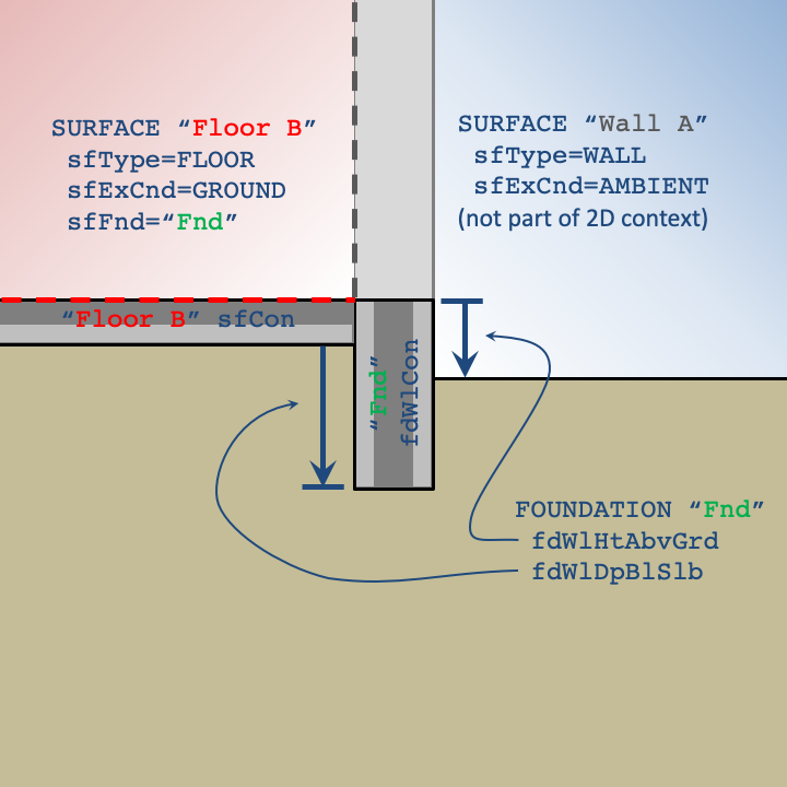
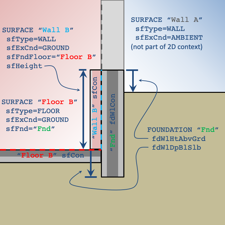
Any ground-contact wall SURFACEs in contact with the ground must refer to a Floor SURFACE object (see sfFndFloor) to indicate which floor shares the same ground boundary condition in the two-dimensional context.
MATERIALs used in a FOUNDATION cannot have variable properties at this time.
Some of the relevant dimensions and properties in the two-dimensional context are defined in the FOUNDATION object (and FNDBLOCK subobjects), but several others are specified by the corresponding SURFACE objects:
- sfFnd
- sfFndFloor
- sfHeight
- sfExpPerim
- sfCon
Some properties applying to all FOUNDATIONs are defined at the TOP level:
- soilCond
- soilSpHt
- soilDens
- grndEmiss
- grndRefl
- grndRf
- farFieldWidth
- deepGrndCnd
- deepGrndDepth
- deepGrndT
- grndMinDim
- grndMaxGrthCoeff
- grndTimeStep
The following data members describe the dimensions and properties of the structural foundation wall. The height of the foundation wall (from the top of the wall to the top of the slab) is defined by sfHeight in wall SURFACEs that specify the same sfFndFloor that references the FOUNDATION (through sfFnd).
Other components of the foundation design (e.g., interior/exterior insulation) as well as other variations in thermal properties within the ground are defined using FNDBLOCK (foundation block) objects. Any number of FNDBLOCKs can appear after the definition of a FOUNDATION to be properly associated.
fdName
Name of foundation; give after the word FOUNDATION. Required for reference from SURFACE objects.
| Units | Legal Range | Default | Required | Variability |
|---|---|---|---|---|
| – | 63 characters | none | Yes | constant |
fdWlHtAbvGrd=float
Distance between the grade level and the top of the foundation wall.
| Units | Legal Range | Default | Required | Variability |
|---|---|---|---|---|
| ft | x \(\geq\) 0 | 0.5 | No | constant |
fdWlDpBlwSlb=float
Distance between the bottom of the slab and the bottom of the foundation wall. Foundation walls typically extend to the bottom of the slab and rest on a footing. If the footing isn’t explicitly modeled as a FNDBLOCK, this value can be extended to approximate the footing.
| Units | Legal Range | Default | Required | Variability |
|---|---|---|---|---|
| ft | x \(\geq\) 0 | 0.0 | No | constant |
fdWlCon=conName
Name of the CONSTRUCTION for the structural foundation wall. In the two-dimensional context, this construction spans from the top of the foundation wall to its depth below the slab (fdWlDpBlwSlb). Any construction on the interior of the wall (spanning from the top of the foundation wall to the top of the slab), must be defined by the sfCon of the corresponding wall surface. Typically, this CONSTRUCTION will be a single layer of poured concrete.
| Units | Legal Range | Default | Required | Variability |
|---|---|---|---|---|
| – | Name of a Construction | none | Yes | constant |
endFoundation
Indicates the end of the foundation definition. Alternatively, the end of the foundation definition can be indicated by the declaration of another object or by END.
| Units | Legal Range | Default | Required | Variability |
|---|---|---|---|---|
| none | No | constant |
4.7 FNDBLOCK
Foundation blocks are materials within the two-dimensional domain beyond those defined by TOP soil properties, the parent FOUNDATION object, and floor and wall SURFACEs. Common examples of using FNDBLOCKs include representing:
- Perimeter slab insulation
- Slab gap insulation
- Partial interior wall insulation
- Exterior horizontal or vertical insulation
- Concrete footings
Each block is represented as a rectangle in the domain by specifying the X (lateral) and Z (vertical) coordinates of two opposite corners. It does not matter which of the four corners of a block are used to define the two points as long as they are opposite corners. The coordinate system for each point is relative to the X and Z references defined by the user. By convention, the positive X direction is away from the building, and the positive Z direction is down. FNDBLOCKs that overlap materials defined by TOP, FOUNDATION, SURFACE objects, or previously defined FNDBLOCKs will override the thermal properties within the extents of the FNDBLOCK.
Each corner point of a FNDBLOCK is defined relative to its reference point. The user may specify reference points to simplify the calculation of corner point coordinates. X and Z point values of zero imply that a point is the same as the reference point. The default for X and Z point values is zero since points will often align with one or both of the reference values. Options for X and Z references are illustrated in the figure below.
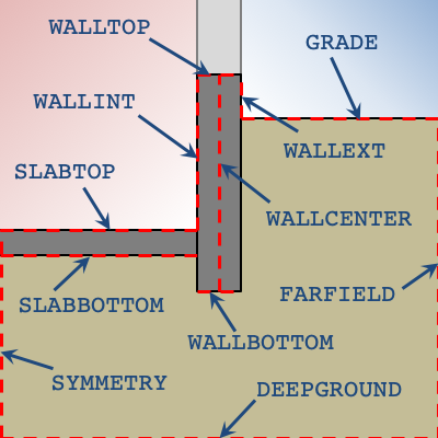
The default X and Z references for the first corner point is WALLINT and WALLTOP, respectively. The second set of references default to the same reference as the first point.
An example of defining FNDBLOCKs for a basement are shown below.
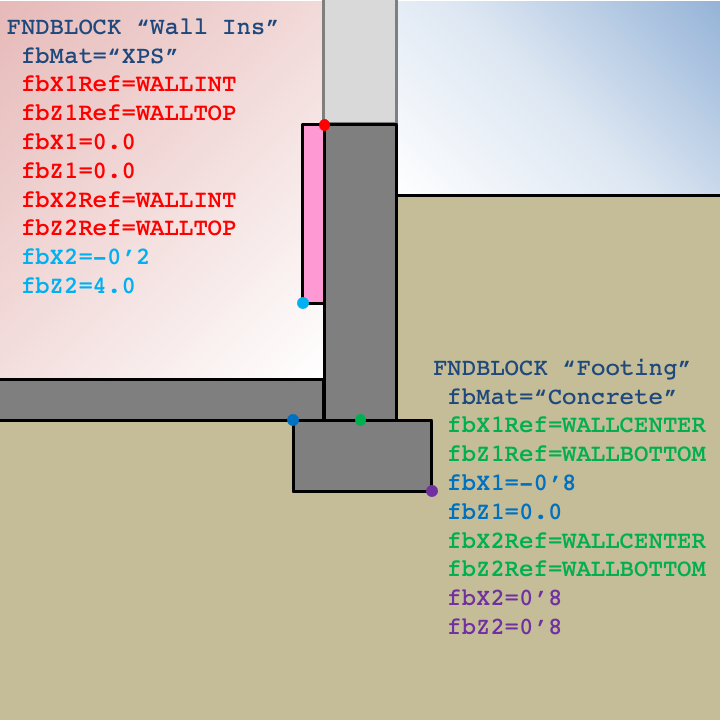
The example for a slab foundation shown below illustrates how leveraging default values can simplify user input.
fbMat=matName
Name of MATERIAL of the foundation block.
| Units | Legal Range | Default | Required | Variability |
|---|---|---|---|---|
| – | Name of a Material | none | Yes | constant |
fbX1Ref=choice
Relative X origin for fbX1 point. Options are:
- SYMMETRY
- WALLINT
- WALLCENTER
- WALLEXT
- FARFIELD
| Units | Legal Range | Default | Required | Variability |
|---|---|---|---|---|
| choices above | WALLINT | No | constant |
fbZ1Ref=choice
Relative Z origin for fbZ1 point. Options are:
- WALLTOP
- GRADE
- SLABTOP
- SLABBOTTOM
- WALLBOTTOM
- DEEPGROUND
| Units | Legal Range | Default | Required | Variability |
|---|---|---|---|---|
| choices above | WALLTOP | No | constant |
fbX1=float
The X position of the first corner of the block relative to fbX1Ref.
| Units | Legal Range | Default | Required | Variability |
|---|---|---|---|---|
| ft | 0.0 | No | constant |
fbZ1=float
The Z position of the first corner of the block relative to fbZ1Ref.
| Units | Legal Range | Default | Required | Variability |
|---|---|---|---|---|
| ft | 0.0 | No | constant |
fbX2Ref=choice
Relative X origin for fbX2 point. Options are:
- SYMMETRY
- WALLINT
- WALLCENTER
- WALLEXT
- FARFIELD
| Units | Legal Range | Default | Required | Variability |
|---|---|---|---|---|
| choices above | same as fbX1Ref | No | constant |
fbZ2Ref=choice
Relative Z origin for fbZ2 point. Options are:
- WALLTOP
- GRADE
- SLABTOP
- SLABBOTTOM
- WALLBOTTOM
- DEEPGROUND
| Units | Legal Range | Default | Required | Variability |
|---|---|---|---|---|
| choices above | same as fbZ1Ref | No | constant |
fbX2=float
The X position of the second corner of the block relative to fbX2Ref.
| Units | Legal Range | Default | Required | Variability |
|---|---|---|---|---|
| ft | 0.0 | No | constant |
fbZ2=float
The Z position of the second corner of the block relative to fbZ2Ref.
| Units | Legal Range | Default | Required | Variability |
|---|---|---|---|---|
| ft | 0.0 | No | constant |
endFndBlock
Indicates the end of the foundation block definition. Alternatively, the end of the foundation block definition can be indicated by the declaration of another object or by END.
| Units | Legal Range | Default | Required | Variability |
|---|---|---|---|---|
| none | No | constant |
4.8 LAYER
LAYER constructs a subobject of class LAYER belonging to the current CONSTRUCTION. LAYER is not recognized except immediately following CONSTRUCTION or another LAYER. The members represent one layer (that optionally includes framing) within the CONSTRUCTION.
The layers should be specified in inside to outside order. A framed layer (lrFrmMat and lrFrmFrac given) is modeled by creating a homogenized material with weighted combined conductivity and volumetric heat capacity. Caution: it is generally preferable to model framed constructions using two separate surfaces (one with framing, one without). At most one framed layer (lrFrmMat and lrFrmFrac given) is allowed per construction.
The layer thickness may be given by lrThk, or matThk of the material, or matThk of the framing material if any. The thickness must be specified at least one of these three places; if specified in more than one place and not consistent, an error message occurs.
lrName
Name of layer (follows “LAYER”). Required only if the LAYER is later referenced in another object, for example with LIKE or ALTER; however, we suggest naming all objects for clearer error messages and future flexibility.
| Units | Legal Range | Default | Required | Variability |
|---|---|---|---|---|
| 63 characters | none | No | constant |
lrMat=matName
Name of primary MATERIAL in layer.
| Units | Legal Range | Default | Required | Variability |
|---|---|---|---|---|
| name of a MATERIAL | none | Yes | constant |
lrThk=float
Thickness of layer.
| Units | Legal Range | Default | Required | Variability |
|---|---|---|---|---|
| ft | x \(>\) 0 | Required if matThk not specified in referenced lrMat | No | constant |
lrFrmMat=matName
Name of framing MATERIAL in layer, if any. At most one layer with lrFrmMat is allowed per CONSTRUCTION. See caution above regarding framed-layer model.
| Units | Legal Range | Default | Required | Variability |
|---|---|---|---|---|
| name of a MATERIAL | no framed layer | No | constant |
lrFrmFrac=float
Fraction of layer that is framing. Must be specified if frmMat is specified. See caution above regarding framed-layer model.
| Units | Legal Range | Default | Required | Variability |
|---|---|---|---|---|
| 0 \(\leq\) x \(\leq\) 1 | no framed layer | Required if lrFrmMat specified, else disallowed | constant |
endLayer
Optional end-of-LAYER indicator; LAYER definition may also be indicated by “END” or just starting the definition of another LAYER or other object.
Related Probes:
4.9 GLAZETYPE
GLAZETYPE constructs an object of class GLAZETYPE that represents a glazing type for use in WINDOWs.
gtName
Name of glazetype. Required for reference from WINDOW objects, below.
| Units | Legal Range | Default | Required | Variability |
|---|---|---|---|---|
| 63 characters | none | Yes | constant |
gtModel=choice
Selects model to be used for WINDOWs based on this GLAZETYPE.
| Units | Legal Range | Default | Required | Variability |
|---|---|---|---|---|
| SHGC, ASHWAT | SHGC | No | constant |
gtU=float
Glazing conductance (U-factor without surface films, therefore not actually a U-factor but a C-factor). Used as wnU default; an error message will be issued if the U value is not given in the window (wnU) nor in the glazeType (gtU). Preferred Approach: To use accurately with standard winter rated U-factor from ASHRAE or NFRC enter as:
gtU = (1/((1/U-factor)-0.85)Where 0.85 is the sum of the interior (0.68) and exterior (0.17) design air film resistances assumed for rating window U-factors. Enter wnInH (usually 1.5=1/0.68) instead of letting it default. Enter the wnExH or let it default. It is important to use this approach if the input includes gnFrad for any gain term. Using approach 2 below will result in an inappropriate internal gain split at the window.
Approach 2. Enter gtU=U-factor and let the wnInH and wnExH default. This approach systematically underestimates the window U-factor because it adds the wnExfilm resistance to 1/U-factor thereby double counting the exterior film resistance. This approach will also yield incorrect results for gnFrad internal gain since the high wnInH will put almost all the gain back in the space.
| Units | Legal Range | Default | Required | Variability |
|---|---|---|---|---|
| Btuh/ft2-oF | x \(>\) 0 | none | No | constant |
gtUNFRC=float
Fenestration system (including frame) U-factor evaluated at NFRC heating conditions. For ASHWAT windows, a value for the NFRC U-factor is required, set via gtUNFRC or wnUNFRC.
| Units | Legal Range | Default | Required | Variability |
|---|---|---|---|---|
| Btuh/ft2-oF | x \(>\) 0 | none | No | constant |
gtSHGC=float
Glazing Solar Heat Gain Coefficient: fraction of normal beam insolation which gets through glass to space inside. We recommend using this to represent the glass normal transmissivity characteristic only, before shading and framing effects
| Units | Legal Range | Default | Required | Variability |
|---|---|---|---|---|
| fraction | 0 \(\leq\) x \(\leq\) 1 | none | Yes | constant |
gtSMSO=float
SHGC multiplier with shades open. May be overriden in the specific window input.
| Units | Legal Range | Default | Required | Variability |
|---|---|---|---|---|
| fraction | 0 \(\leq\) x \(\leq\) 1 | 1.0 | No | Monthly - Hourly |
gtSMSC=float
SHGC multiplier with shades closed. May be overriden in the specific window input.
| Units | Legal Range | Default | Required | Variability |
|---|---|---|---|---|
| fraction | 0 \(\leq\) x \(\leq\) 1 | gtSMSO (no shades) | No | Monthly - Hourly |
gtFMult=float
Framing multiplier used if none given in window, for example .9 if frame and mullions reduce the solar gain by 10%. Default of 1.0 implies frame/mullion effects allowed for in gtSHGC’s or always specified in Windows.
| Units | Legal Range | Default | Required | Variability |
|---|---|---|---|---|
| fraction | 0 \(\leq\) x \(\leq\) 1 | gtSHGCO | No | Monthly - Hourly |
gtPySHGC =float
Four float values separated by commas. Coefficients for incidence angle SHGC multiplier polynomial applied to gtSHGC to determine beam transmissivity at angles of incidence other than 90 degrees. The values are coefficients for first through fourth powers of the cosine of the incidence angle; there is no constant part. An error message will be issued if the coefficients do not add to one. They are used in the following computation:
angle = incidence angle of beam radiation, measured from normal to glass.
cosI = cos( angle)
angMult = a*cosI + b*cosI^2 + c*cosI^3 + d*cosI^4
beamXmisvty = gtSHGCO * angMult (shades open)
| Units | Legal Range | Default | Required | Variability |
|---|---|---|---|---|
| float | any | none | Yes | constant |
gtDMSHGC=float
SHGC diffuse multiplier, applied to gtSHGC to determine transmissivity for diffuse radiation.
| Units | Legal Range | Default | Required | Variability |
|---|---|---|---|---|
| fraction | 0 \(\leq\) x \(\leq\) 1 | none | Yes | constant |
gtDMRBSol=float
SHGC diffuse multiplier, applied to qtSHGC to determine transmissivity for diffuse radiation reflected back out the window. Misnamed as a reflectance. Assume equal to DMSHGC if no other data available.
| Units | Legal Range | Default | Required | Variability |
|---|---|---|---|---|
| fraction | 0 \(\leq\) x \(\leq\) 1 | none | Yes | constant |
gtNGlz=int
Number of glazings in the Glazetype (bare glass only, not including any interior or exterior shades).
| Units | Legal Range | Default | Required | Variability |
|---|---|---|---|---|
| 0 \(<\) x \(\leq\) 4 | 2 | No | constant |
gtExShd=choice
Exterior shading type (ASHWAT only).
| Units | Legal Range | Default | Required | Variability |
|---|---|---|---|---|
| NONE INSCRN | NONE | No | constant |
gtInShd=choice
Interior shade type (ASHWAT only).
| Units | Legal Range | Default | Required | Variability |
|---|---|---|---|---|
| NONE DRAPEMED | NONE | No | constant |
gtDirtLoss=float
Glazing dirt loss factor.
| Units | Legal Range | Default | Required | Variability |
|---|---|---|---|---|
| fraction | 0 \(\leq\) x \(\leq\) 1 | 0 | No | constant |
endGlazeType
Optional to indicates the end of the Glazetype. Alternatively, the end of the GLAZETYPE definition can be indicated by “END” or by beginning another object
| Units | Legal Range | Default | Required | Variability |
|---|---|---|---|---|
| none | No | constant |
Related Probes:
4.10 METER
A METER object is a user-defined “device” that records energy consumption of equipment as simulated by CSE. The user defines METERs with the desired names, then assigns energy uses of specific equipment to the desired meters using commands described under each equipment type’s class description (AIRHANDLER, TERMINAL, etc.). Additional energy use from equipment not simulated by CSE (except optionally for its effect on heating and cooling loads) can also be charged to METERs (see GAIN). The data accumulated by meters can be reported at hourly, daily, monthly, and annual (run) intervals by using REPORTs and EXPORTs of type MTR.
Meters account for energy use in the following pre-defined categories, called end uses. The abbreviations in parentheses are used in MTR report headings (and for gnMeter input, below). You also get a column for the net total on the meter (abbreviated “Tot”).
| Clg | Cooling |
| Htg | Heating (includes heat pump compressor) |
| HPBU | Heat pump resistance heating (backup and defrost) |
| DHW | Domestic (service) hot water |
| DHWBU | Domestic (service) hot water heating backup (HPWH resistance) |
| DHWMFL | Domestic (service) hot water heating multi-family loop pumping and loss makeup |
| FANC | Fans, AC and cooling ventilation |
| FANH | Fans, heating |
| FANV | Fans, IAQ venting |
| FAN | Fans, other purposes |
| AUX | HVAC auxiliaries such as pumps |
| PROC | Process |
| LIT | Lighting |
| RCP | Receptacles |
| EXT | Exterior lighting |
| REFR | Refrigeration |
| DISH | Dishwashing |
| DRY | Clothes drying |
| WASH | Clothes washing |
| COOK | Cooking |
| USER1 | User-defined category 1 |
| USER2 | User-defined category 2 |
| BT | Battery charge power |
| PV | Photovoltaic power generation |
The user has complete freedom over how many meters are defined and how equipment is assigned to them. At one extreme, a single meter “Electricity” could be defined and have all of electrical uses assigned to it. On the other hand, definition of separate meters “Elect_Fan1”, “Elect_Fan2”, and so forth allows accounting of the electricity use for individual pieces of equipment. Various groupings are possible: for example, in a building with several air handlers, one could separate the energy consumption of the fans from the coils, or one could separate the energy use by air handler, or both ways, depending on the information desired from the run.
The members that assign energy use to meters include:
- GAIN: gnMeter, gnEndUse
- ZONE: xfanMtr
- IZXFER: izfanMtr
- RSYS: rsElecMtr, rsFuelMtr
- DHWSYS: wsElecMtr, wsFuelMtr
- DHWHEATER: whElectMtr, whFuelMtr
- DHWPUMP: wpElecMtr
- DHWLOOPPUMP: wlpElecMtr
- PVARRAY: pvElecMeter
- TERMINAL: tuhcMtr, tfanMtr
- AIRHANDLER: sfanMtr, rfanMtr, ahhcMtr, ahccMtr, ahhcAuxOnMtr, ahhcAuxOffMtr, ahhcAuxFullOnMtr, ahhcAuxOnAtAllMtr, ahccAuxOnMtr, ahccAuxOffMtr, ahccAuxFullOnMtr, ahccAuxOnAtAllMtr
- BOILER: blrMtr, blrpMtr, blrAuxOnMtr, blrAuxOffMtr, blrAuxFullOnMtr, blrAuxOnAtAllMtr
- CHILLER: chMtr, chppMtr, chcpMtr, chAuxOnMtr, chAuxOffMtr, chAuxFullOnMtr, chAuxOnAtAllMtr
- TOWERPLANT: tpMtr
The end use can be specified by the user only for GAINs and PVARRAYs; in other cases it is hard-wired to Clg, Htg, FanC, FanH, FanV, Fan, or Aux as appropriate.
mtrName
Name of meter: required for assigning energy uses to the meter elsewhere.
| Units | Legal Range | Default | Required | Variability |
|---|---|---|---|---|
| 63 characters | none | Yes | constant |
mtrDemandRate=float
DmdCost per Btu of demand, for a month.
| Units | Legal Range | Default | Required | Variability |
|---|---|---|---|---|
| N/A | No | constant |
mtrRate=float
Cost of energy use per Btu.
| Units | Legal Range | Default | Required | Variability |
|---|---|---|---|---|
| N/A | No | constant |
mtrSubmeters=list of up to 50 METERs
A comma-separate list of METERs that are accumulated into this METER with optional multipliers (see mtrSubmeterMults). Submeters facilitate flexible categorization of energy results. In addition, use of mtrSubmeterMults allows energy results from a representative model to be scaled and included in overall results. For example, a typical zone could be used to represent 5 similar spaces. The energy uses of the typical zone could be assigned to a dedicated METER that is accumulated to a main METER with a multiplier of 5. Rules –
- A METER cannot reference itself as a submeter.
- A given METER can be referenced only once in the mtrSubmeters list.
- Circular references are not allowed.
| Units | Legal Range | Default | Required | Variability |
|---|---|---|---|---|
| names of METERs | No | constant |
mtrSubmeterMults=list of up to 50 floats
Submeter multipliers. Use cases for multipliers include –
- Scaling results from portions of a model to approximate the behavior of multiple similar aspects (e.g. multiple floors in a high-rise building)
- Tracking energy use during selected time intervals; for example, peak-period energy use could be metered for certain hours via scheduled multipliers of 0 or 1.
A note re default values: if mtrSubmeterMults is omitted, all multipliers are defaulted to 1. However, when mtrSubmeterMults is included, a multiplier value should be provided for each METER listed in mtrSubmeters since unspecified values are set to 0.
| Units | Legal Range | Default | Required | Variability |
|---|---|---|---|---|
| 1 | No | hourly |
endMeter
Indicates the end of the meter definition. Alternatively, the end of the meter definition can be indicated by the declaration of another object or by END.
| Units | Legal Range | Default | Required | Variability |
|---|---|---|---|---|
| none | No | constant |
Related Probes:
4.11 DHWMETER
A DHWMETER object is a user-defined “device” that records water consumption as simulated by CSE. The data accumulated by DHWMETERs can be reported at hourly, daily, monthly, and annual (run) intervals by using REPORTs and EXPORTs of type DHWMTR. Water use is reported in gallons.
DHWMETERs account for water use in the following pre-defined end uses. The abbreviations in parentheses are used in DHWMTR report headings.
- Total water use (Total)
- Unknown end use (Unknown)
- Miscellaneous draws (Faucet)
- Shower (Shower)
- Bathtub (Bath)
- Clothes washer (CWashr)
- Dishwasher (DWashr)
DHWSYS items wsWHhwMtr and wsFXhwMtr specify the DHWMETER(s) to which water consumption is accumulated.
dhwMtrName
Name of meter: required for assigning water uses to the DHWMETER.
| Units | Legal Range | Default | Required | Variability |
|---|---|---|---|---|
| 63 characters | none | Yes | constant |
endDhwMeter
Related Probes:
4.12 AFMETER
An AFMETER object is a user-defined “device” that records zone air flows as simulated by CSE. The user defines AFMETERs and assigns them to zones (see ZONE znAFMtr).
Air flow is recorded in standard air cfm (density 0.075 lb/ft3) at subhour, hour, day, month, and year intervals. At intervals of an hour and longer, values are averaged. Flows are categorized according to IZXFER izAFCat.
If any AFMETERs are defined, an additional AFMETER “sum_of_AFMETERs” is automatically created where the sums of all user-define AFMETERs are accumulated.
Note that only AirNet flows are recorded.
AFMETER results can be REPORTed using rpType=AFMTR (or EXPORTed using exType=AFMTR). See Air Flow Meter Report.
afMtrName
Name of meter: required for assigning air flows to the AFMETER.
| Units | Legal Range | Default | Required | Variability |
|---|---|---|---|---|
| 63 characters | none | Yes | constant |
endAFMeter
Indicates the end of the meter definition. Alternatively, the end of the meter definition can be indicated by the declaration of another object or by END.
| Units | Legal Range | Default | Required | Variability |
|---|---|---|---|---|
| none | No | constant |
Related Probes:
4.13 LOADMETER
A LOADMETER object is a user-defined “device” that records heating and cooling loads as computed by CSE. The user defines LOADMETERs and assigns them to ZONEs and/or RSYSs (see ZONE znLoadMtr and RSYS rsLoadMtr).
Loads are accumulated for subhour, hour, day, month, and annual intervals. All values are in Btu. Values >0 indicated heat into the process or zone – thus heating loads are >0 and cooling loads are <0.
LOADMETER results must be reported using user-defined REPORTs or EXPORTs. For example –
REPORT rpType=UDT rpFreq=Month rpDayBeg=Jan 1 rpDayEnd=Dec 31
    REPORTCOL colHead="mon" colVal=$Month colWid=3
    REPORTCOL colHead="Heating" colVal=@LoadMeter[ 1].M.qHtg colDec=0 colWid=10
    REPORTCOL colHead="Cooling" colVal=@LoadMeter[ 1].M.qClg colDec=0 colWid=10
ldMtrName
Name of LOADMETER: required for assigning to ZONEs and RSYSs.
| Units | Legal Range | Default | Required | Variability |
|---|---|---|---|---|
| 63 characters | none | Yes | constant |
lmtSubmeters=list of up to 50 LOADMETERs
A comma-separate list of LOADMETERs that are accumulated into this LOADMETER with optional multipliers (see lmtSubmeterMults). Submeters facilitate flexible categorization of loads results. In addition, use of lmtSubmeterMults allows load results from a representative model to be scaled and included in overall results. For example, a typical zone could be used to represent 5 similar spaces. The loads calculated for the typical zone could be assigned to a dedicated LOADMETER and that LOADMETER accumulated to a main LOADMETER with a multiplier of 5. Rules –
- A LOADMETER cannot reference itself as a submeter.
- A given LOADMETER can be referenced only once in the lmtSubmeters list.
- Circular references are not allowed.
| Units | Legal Range | Default | Required | Variability |
|---|---|---|---|---|
| names of LOADMETERs | No | constant |
lmtSubmeterMults=list of up to 50 floats
Submeter multipliers.
A note re default values: if lmtSubmeterMults is omitted, all multipliers are defaulted to 1. However, when lmtSubmeterMults is included, a multiplier value should be provided for each LOADMETER listed in lmtSubmeters since unspecified values are set to 0.
| Units | Legal Range | Default | Required | Variability |
|---|---|---|---|---|
| 1 | No | subhourly |
endLOADMETER
Indicates the end of the meter definition. Alternatively, the end of the meter definition can be indicated by the declaration of another object or by END.
| Units | Legal Range | Default | Required | Variability |
|---|---|---|---|---|
| none | No | constant |
Related Probes:
4.14 ACCUMULATOR
An ACCUMULATOR is driven by arbitrary subhourly expression value computed during the CSE simulation and calculates minimum, maximum, mean, and sum values for hour, day, month, and year intervals. In addition, timestamps are retained for the minimum and maximum values. ACCUMULATORs are useful for summarizing and reporting values for which there is not built-in accounting (for example, ZNRES or RSYSRES). One common use case is for reporting hour average values of internal variables that vary subhourly.
ACCUMULATORs are “observing” devices – they have no effect on the CSE building model or calculations. ACCUMULATOR values must be reported using user-defined REPORTs or EXPORTs.
As a simple example, a report of monthly outdoor drybulb temperatures can be generated as follows –
ACCUMULATOR "ACTDB" acmValue=$tdbosh

REPORT "TODB" rpType=UDT rpFreq=Month rpTitle="Outdoor drybulb temp (F)"
  REPORTCOL colHead="Mon" colVal=$Month colWid=3
  REPORTCOL colHead="Min" colVal=@Accumulator[ "ACTDB"].M.acmMin colDec=2 colWid=6
  REPORTCOL colHead="Mean" colVal=@Accumulator[ "ACTDB"].M.acmMean colDec=2 colWid=6
  REPORTCOL colHead="Max" colVal=@Accumulator[ "ACTDB"].M.acmMax colDec=2 colWid=6
REPORT rpType=UDT rpFreq=Year rpHeader=No
  REPORTCOL colVal="Yr" colWid=3
  REPORTCOL colVal=@Accumulator[ "ACTDB"].Y.acmMin colDec=2 colWid=6
  REPORTCOL colVal=@Accumulator[ "ACTDB"].Y.acmMean colDec=2 colWid=6
  REPORTCOL colVal=@Accumulator[ "ACTDB"].Y.acmMax colDec=2 colWid=6
Resulting output –
  Outdoor drybulb temp (F)

  Mon    Min   Mean    Max
  --- ------ ------ ------
    1  28.22  46.87  60.08
    2  32.00  49.26  69.98
    3  42.08  60.79  91.40
    4  34.70  58.13  79.16
    5  44.42  67.07  97.88
    6  50.36  73.43 107.96
    7  55.04  74.02 101.48
    8  53.60  74.99 104.18
    9  48.92  69.24  97.52
   10  47.84  64.00  98.42
   11  32.54  54.47  77.00
   12  28.04  46.58  64.04

   Yr  28.04  61.65 107.96
Generalizing what is illustrated, probing @accumulator [ ].H yields statistics for the current hour, .D for the current day, .M the current month, and .Y for the year (or, more precisely, the full run, which may or may not be a full year).
A complete list of the available statistics for each interval is found in the ACCUMULATOR probe documentation.
Note: The initial version of ACCUMULATOR contains unresolved bugs related to the timing of the determination of acmValue. In some cases, acmValue is set to the expression value from the prior substep. This is being investigated.
acmName
Name of ACCUMULATOR: required for referencing in reports.
| Units | Legal Range | Default | Required | Variability |
|---|---|---|---|---|
| 63 characters | none | Yes | constant |
acmValue=float
The value being accumulated. Generally expression with subhourly variability.
| Units | Legal Range | Default | Required | Variability |
|---|---|---|---|---|
| any | Yes | subhourly |
endACCUMULATOR
Indicates the end of the ACCUMULATOR definition. Alternatively, the end of the definition can be indicated by the declaration of another object or by END.
| Units | Legal Range | Default | Required | Variability |
|---|---|---|---|---|
| none | No | constant |
Related Probes:
4.15 ZONE
ZONE constructs an object of class ZONE, which describes an area of the building to be modeled as having a uniform condition. ZONEs are large, complex objects and can have many subobjects that describe associated surfaces, shading devices, HVAC equipment, etc.
4.15.1 ZONE General Members
znName
Name of zone. Enter after the word ZONE; no “=” is used.
| Units | Legal Range | Default | Required | Variability |
|---|---|---|---|---|
| 63 characters | none | Yes | constant |
znModel=choice
Selects model for zone.
| CNE | Older central difference model based on original CALPAS methods. Not fully supported and not suitable for current compliance applications. |
| CZM | Conditioned zone model. Forward-difference, short time step methods are used. |
| UZM | Unconditioned zone model. Identical to CZM except heating and cooling are not supported. Typically used for attics, garages, and other ancillary spaces. |
| Units | Legal Range | Default | Required | Variability |
|---|---|---|---|---|
| choices above | CNE | No | constant |
znArea=float
Nominal zone floor area.
| Units | Legal Range | Default | Required | Variability |
|---|---|---|---|---|
| ft2 | x \(>\) 0 | none | Yes | constant |
znVol=float
Nominal zone volume.
| Units | Legal Range | Default | Required | Variability |
|---|---|---|---|---|
| ft3 | x \(>\) 0 | none | Yes | constant |
znAzm=float
Zone azimuth with respect to bldgAzm. All surface azimuths are relative to znAzm, so that the zone can be rotated by changing this member only. Values outside the range 0o to 360o are normalized to that range.
| Units | Legal Range | Default | Required | Variability |
|---|---|---|---|---|
| degrees | unrestricted | 0 | No | constant |
znFloorZ=float
Nominal zone floor height relative to arbitrary 0 level. Used re determination of vent heights
| Units | Legal Range | Default | Required | Variability |
|---|---|---|---|---|
| ft | unrestricted | 0 | No | constant |
znCeilingHt=float
Nominal zone ceiling height relative to zone floor (typically 8 – 10 ft).
| Units | Legal Range | Default | Required | Variability |
|---|---|---|---|---|
| ft | x \(>\) 0 | znVol / znArea | No | constant |
znEaveZ=float
Nominal eave height above ground level. Used re calculation of local surface wind speed. This in turn influences outside convection coefficients in some surface models and wind-driven air leakage.
| Units | Legal Range | Default | Required | Variability |
|---|---|---|---|---|
| ft | x \(>\) 0 | znFloorZ + infStories8* | No | constant |
znCAir=float
Zone “air” heat capacity: represents heat capacity of air, furniture, “light” walls, and everything in zone except surfaces having heat capacity (that is, non-QUICK surfaces).
| Units | Legal Range | Default | Required | Variability |
|---|---|---|---|---|
| Btu/oF | x \(\geq\) 0 | 3.5 znArea* | No | constant |
znHcAirX=float
Zone air exchange rate used in determination of interior surface convective coefficients. This item is generally used only for model testing.
| Units | Legal Range | Default | Required | Variability |
|---|---|---|---|---|
| ACH | x \(>\) 0 | as modeled | No | subhourly |
znHcFrcF=float
Zone surface forced convection factor. Default interior surface convective transfer is modeled as a combination of forced and natural convection. hcFrc = znHcFrcF * ACH^.8, where ACH = znHcAirX + heat pump water heater evaporator air exchange rate See CSE Engineering Documentation.
| Units | Legal Range | Default | Required | Variability |
|---|---|---|---|---|
| Btuh/ft2-oF | .2 | .2 | No | hourly |
znHIRatio=float
Zone hygric inertia ratio. In zone moisture balance calculations, the effective dry-air mass = znHIRatio * (zone dry air mass). This enhancement can be used to represente the moisture storage capacity of zone surfaces and contents.
| Units | Legal Range | Default | Required | Variability |
|---|---|---|---|---|
| x \(>\) 0 | 1 | No | constant |
znSC=float
Zone shade closure. Determines insolation through windows (see WINDOW members wnSCSO and wnSCSC) and solar gain distribution: see SGDIST members sgFSO and sgFSC. 0 represents shades open; 1 represents shades closed; intermediate values are allowed. An hourly variable CSE expression may be used to schedule shade closure as a function of weather, time of year, previous interval HVAC use or zone temperature, etc.
| Units | Legal Range | Default | Required | Variability |
|---|---|---|---|---|
| 0 \(\leq\) x \(\leq\) 1 | 1 when cooling was used in previous hour, else 0 | No | hourly |
znTH=float
Heating set point used (and required) when znModel=CZM and zone has no terminals.
| Units | Legal Range | Default | Required | Variability |
|---|---|---|---|---|
| oF | 0 < znTH < znTC | none | Per above | subhourly |
znTD=float
Desired set point (temperature maintained with ventilation if possible) for znModel=CZM. Must be specified when zone ventilation is active.
| Units | Legal Range | Default | Required | Variability |
|---|---|---|---|---|
| oF | x > 0; znTH < znTD < znTC | none | if venting | subhourly |
znTC=float
Cooling set point used (and required) when znModel=CZM and zone has no terminals.
| Units | Legal Range | Default | Required | Variability |
|---|---|---|---|---|
| oF | 0 < znTC > znTH | none | Per above | subhourly |
znModel = CZM zone heating and cooling is provided either via an RSYS HVAC system, by “magic” heat transfers specified by znQxxx items, or via TERMINAL (s). One of these must be defined.
znRSys=rsysName
Name of RSYS providing heating, cooling, and optional central fan integrated ventilation to this zone.
| Units | Legal Range | Default | Required | Variability |
|---|---|---|---|---|
| RSYS name | (no RSYS) | No | constant |
znQMxH=float
Heating capacity at current conditions
| Units | Legal Range | Default | Required | Variability |
|---|---|---|---|---|
| Btuh | x \(\geq\) 0 | none | No | hourly |
znQMxHRated=float
Rated heating capacity
| Units | Legal Range | Default | Required | Variability |
|---|---|---|---|---|
| Btuh | x \(\geq\) 0 | none | No | constant |
znQMxC=float
Cooling capacity at current conditions
| Units | Legal Range | Default | Required | Variability |
|---|---|---|---|---|
| Btuh | x \(\leq\) 0 | none | No | hourly |
znQMxCRated=float
Rated cooling capacity
| Units | Legal Range | Default | Required | Variability |
|---|---|---|---|---|
| Btuh | x \(\leq\) 0 | none | No | constant |
4.15.2 ZONE Infiltration
The following control a simplified air change plus leakage area model. The Sherman-Grimsrud model is used to derive air flow rate from leakage area and this rate is added to the air changes specified with infAC. Note that TOP.windF does not modify calculated infiltration rates, since the Sherman-Grimsrud model uses its own modifiers. See also AirNet models available via IZXFER.
infAC=float
Zone infiltration air changes per hour.
| Units | Legal Range | Default | Required | Variability |
|---|---|---|---|---|
| 1/hr | x \(\geq\) 0 | 0.5 | No | hourly |
infELA=float
Zone effective leakage area (ELA).
| Units | Legal Range | Default | Required | Variability |
|---|---|---|---|---|
| in2 | x \(\geq\) 0 | 0.0 | No | hourly |
infShld=int
Zone local shielding class, used in derivation of local wind speed for ELA infiltration model, wind-driven AirNet leakage, and exterior surface coefficients. infShld values are –
| 1 | no obstructions or local shielding |
| 2 | light local shielding with few obstructions |
| 3 | moderate local shielding, some obstructions within two house heights |
| 4 | heavy shielding, obstructions around most of the perimeter |
| 5 | very heavy shielding, large obstructions surrounding the perimeter within two house heights |
| Units | Legal Range | Default | Required | Variability |
|---|---|---|---|---|
| 1 \(\leq\) x \(\leq\) 5 | 3 | No | constant |
infStories=int
Number of stories in zone, used in ELA model.
| Units | Legal Range | Default | Required | Variability |
|---|---|---|---|---|
| 1 \(\leq\) x \(\leq\) 3 | 1 | No | constant |
znWindFLkg=float
Wind speed modifier factor. The weather file wind speed is multiplied by this factor to yield a local wind speed for use in infiltration and convection models.
| Units | Legal Range | Default | Required | Variability |
|---|---|---|---|---|
| x \(\geq\) 0 | derived from znEaveZ and infShld | No | constant |
znAFMtr=afMtrName
Name of an AFMETER object, if any, to which zone AirNet air flows are recorded. ZnAFMtr defines a pressure boundary for accounting purposes. Multiple zones having the same AFMETER are treated as a single volume – interzone flows within that volume are not recorded. For example, to obtain “building total” flow data, a common AFMETER could be assigned to several conditioned zones but not to adjacent unconditioned zones such as attic spaces.
| Units | Legal Range | Default | Required | Variability |
|---|---|---|---|---|
| name of an AFMETER | not recorded | No | constant |
znLoadMtr=ldMtrName
Name of a LOADMETER object, if any, to which zone heating and cooling loads are recorded.
| Units | Legal Range | Default | Required | Variability |
|---|---|---|---|---|
| name of a LOADMETER | not recorded | No | constant |
4.15.3 ZONE Exhaust Fan
Presence of an exhaust fan in a zone is indicated by specifying a non-zero design flow value (xfanVfDs).
Zone exhaust fan model implementation is incomplete as of July, 2011. The current code calculates energy use but does not account for the effects of air transfer on room heat balance. IZXFER provides a more complete implementation.
xfanFOn=float
Exhaust fan on fraction. On/off control assumed, so electricity requirement is proportional to run time.
| Units | Legal Range | Default | Required | Variability |
|---|---|---|---|---|
| fraction | 0 \(\leq\) x \(\leq\) 1 | 1 | No | hourly |
Example: The following would run an exhaust fan 70% of the time between 8 AM and 5 PM:
    xfanFOn = select( (\$hour >= 7 && \$hour < 5), .7,
default, 0 );xfanVfDs=float
Exhaust fan design flow; 0 or not given indicates no fan.
| Units | Legal Range | Default | Required | Variability |
|---|---|---|---|---|
| cfm | x \(\geq\) 0 | 0, no fan | If fan present | constant |
xfanPress=float
Exhaust fan external static pressure.
| Units | Legal Range | Default | Required | Variability |
|---|---|---|---|---|
| inches | 0.05 \(\leq\) x \(\leq\) 1.0 | 0.3 | No | constant |
Only one of xfanElecPwr, xfanEff, and xfanShaftBhp may be given: together with xfanVfDs and xfanPress, any one is sufficient for CSE to detemine the others and to compute the fan heat contribution to the air stream.
xfanElecPwr=float
Fan input power per unit air flow (at design flow and pressure).
| Units | Legal Range | Default | Required | Variability |
|---|---|---|---|---|
| W/cfm | x \(>\) 0 | derived from xfanEff | If xfanEff and xfanShaftBhp not present | constant |
xfanEff=float
Exhaust fan/motor/drive combined efficiency.
| Units | Legal Range | Default | Required | Variability |
|---|---|---|---|---|
| fraction | 0 \(\leq\) x \(\leq\) 1 | 0.08 | No | constant |
xfanShaftBhp=float
Fan shaft power at design flow and pressure.
| Units | Legal Range | Default | Required | Variability |
|---|---|---|---|---|
| BHP | x \(>\) 0 | derived from xfanElecPwr and xfanVfDs | If xfanElecPwr not present | constant |
xfanMtr=mtrName
Name of METER object, if any, by which fan’s energy use is recorded (under end use category “fan”).
| Units | Legal Range | Default | Required | Variability |
|---|---|---|---|---|
| name of a METER | not recorded | No | constant |
endZone
Indicates the end of the zone definition. Alternatively, the end of the zone definition can be indicated by the declaration of another object or by “END”. If END or endZone is used, it should follow the definitions of the ZONE’s subobjects such as GAINs, SURFACEs, TERMINALs, etc.
| Units | Legal Range | Default | Required | Variability |
|---|---|---|---|---|
| none | No | constant |
Related Probes:
4.16 GAIN
A GAIN object adds sensible and/or latent heat to the ZONE, and/or adds arbitrary energy use to a METER. GAINs may be subobjects of ZONEs and are normally given within the input for their ZONE. As many GAINs as desired (or none) may be given for each ZONE. Alternatively, GAINs may be subobjects of TOP and specify gnZone to specify their associate zone.
Each gain has an amount of power (gnPower), which may optionally be accumulated to a METER (gnMeter). The power may be distributed to the zone, plenum, or return as sensible heat with an optional fraction radiant, or to the zone as latent heat (moisture addition), or not.
4.16.1 Gain zones
The gain to the zone may be further divided into convective sensible, radiant sensible and latent heat via the gnFrRad and gnFrLat members; the plenum and return gains are assumed all convective sensible.
In the CNE zone mode, the radiant internal gain is distributed to the surfaces in the zone, rather than going directly to the zone “air” heat capacity (znCAir). A simple model is used – all surfaces are assumed to be opaque and to have the same (infrared) absorptivity – even windows. Along with the assumption that the zone is spherical (implicit in the current treatment of solar gains), this allows distribution of gains to surfaces in proportion to their area, without any absorptivity or transmissivity calculations. The gain for windows and quick-model surfaces is assigned to the znCAir, except for the portion which conducts through the surface to the other side rather than through the surface film to the adjacent zone air; the gain to massive (delayed-model) surfaces is assigned to the side of surface in the zone with the gain.
Radiant internal gains are included in the IgnS (Sensible Internal Gain) column in the zone energy balance reports. (They could easily be shown in a separate IgnR column if desired.) Any energy transfer shows two places in the ZEB report, with opposite signs, so that the result is zero – otherwise it wouldn’t be an energy balance. The rest of the reporting story for radiant internal gains turns out to be complex. The specified value of the radiant gain (gnPower * gnFrZn * gnFrRad) shows in the IgnS column. To the extent that the gain heats the zone, it also shows negatively in the Masses column, because the zone CAir is lumped with the other masses. To the extent that the gain heats massive surfaces, it also shows negatively in the masses column. To the extent that the gain conducts through windows and quick-model surfaces, it shows negatively in the Conduction column. If the gain conducts through a quick-model surface to another zone, it shows negatively in the Izone (Interzone) column, positively in the Izone column of the receiving zone, and negatively in the receiving zone’s Masses or Cond column.
gnName
Name of gain; follows the word GAIN if given.
| Units | Legal Range | Default | Required | Variability |
|---|---|---|---|---|
| 63 characters | none | No | constant |
gnZone=znName
Name of ZONE to which heat gains are added. Omitted when GAIN is given as a ZONE subobject. If a TOP subobject (i.e., not a ZONE subobject) and znZone is omitted, heat gains are discarded but energy use is still recorded to gnMeter. This feature can be used to represent energy uses that our outside of conditioned zones (e.g. exterior lighting).
| Units | Legal Range | Default | Required | Variability |
|---|---|---|---|---|
| name of ZONE | parent zone if any | No | constant |
gnPower=float
Rate of heat addition/energy use. Negative gnPower values may be used to represent heat removal/energy generation. Expressions containing functions are commonly used with this member to schedule the gain power on a daily and/or hourly basis. Refer to the functions section in Section 4 for details and examples.
All gains, including electrical, are specified in Btuh units unless associated with DHW use (see gnCtrlDHWSYS), in which case gnPower is specified in Btuh/gal. Note that meter reporting of internal gain is in MBtu (millions of Btu) by default.
| Units | Legal Range | Default | Required | Variability |
|---|---|---|---|---|
| Btuh | no restrictions | none | Yes | hourly |
gnMeter=choice
Name of meter by which this GAIN’s gnPower is recorded. If omitted, gain is assigned to no meter and energy use is not accounted in CSE simulation reports; thus, gnMeter should only be omitted for “free” energy sources.
| Units | Legal Range | Default | Required | Variability |
|---|---|---|---|---|
| name of METER | none | No | constant |
gnEndUse=choice
Meter end use to which the GAIN’s energy use should be accumulated.
| Clg | Cooling |
| Htg | Heating (includes heat pump compressor) |
| HPBU | Heat pump resistance heating (backup and defrost) |
| DHW | Domestic (service) hot water |
| DHWBU | Domestic (service) hot water heating backup (HPWH resistance) |
| DHWMFL | Domestic (service) hot water heating multi-family loop pumping and loss makeup |
| FANC | Fans, AC and cooling ventilation |
| FANH | Fans, heating |
| FANV | Fans, IAQ venting |
| FAN | Fans, other purposes |
| AUX | HVAC auxiliaries such as pumps |
| PROC | Process |
| LIT | Lighting |
| RCP | Receptacles |
| EXT | Exterior lighting |
| REFR | Refrigeration |
| DISH | Dishwashing |
| DRY | Clothes drying |
| WASH | Clothes washing |
| COOK | Cooking |
| USER1 | User-defined category 1 |
| USER2 | User-defined category 2 |
| BT | Battery charge power |
| PV | Photovoltaic power generation |
| Units | Legal Range | Default | Required | Variability |
|---|---|---|---|---|
| Codes listed above | none | Required if gnMeter is given | constant |
The gnFrZn, gnFrPl, and gnFrRtn members allow you to allocate the gain among the zone, the zone’s plenum, and the zone’s return air flow. Values that total to more than 1.0 constitute an error. If they total less than 1, the unallocated portion of the gain is recorded by the meter (if specified) but not transferred into the building. By default, all of the gain not directed to the return or plenum goes to the zone.
gnFrZn=float
Fraction of gain going to zone. gnFrLat (below) gives portion of this gain that is latent, if any; the remainder is sensible.
| Units | Legal Range | Default | Required | Variability |
|---|---|---|---|---|
| 0 \(\leq\) x \(\leq\) 1 | 1. | No | hourly |
gnFrPl=float
Fraction of gain going to plenum.
| Units | Legal Range | Default | Required | Variability |
|---|---|---|---|---|
| gnFrZn + gnFrPl + gnFrRtn \(\leq\) 1 | 0. | No | hourly |
gnFrRtn=float
Fraction of gain going to return.
| Units | Legal Range | Default | Required | Variability |
|---|---|---|---|---|
| gnFrZn + gnFrPl + gnFrRtn \(\leq\) 1 | 0. | No | hourly |
gnFrRad=float
Fraction of total gain going to zone (gnFrZn) that is radiant rather than convective or latent.
| Units | Legal Range | Default | Required | Variability |
|---|---|---|---|---|
| 0 \(\leq\) x \(\leq\) 1 | 0.0 | No | hourly |
gnFrLat=float
Fraction of total gain going to zone (gnFrZn) that is latent heat (moisture addition).
| Units | Legal Range | Default | Required | Variability |
|---|---|---|---|---|
| 0 \(\le\) x \(\le\) 1 | 0.0 | No | hourly |
gnDlFrPow=float
Hourly power reduction factor, typically used to modify lighting power to account for daylighting.
| Units | Legal Range | Default | Required | Variability |
|---|---|---|---|---|
| 0 \(\le\) x \(\le\) 1 | 1.0 | No | hourly |
gnCtrlDHWSYS=dhwsysName
Name of a DHWSYS whose water use modulates gnPower. For example, electricity use of water-using appliances (e.g. dishwasher or clothes washer) can be modeled based on water use, ensuring that the uses are synchronized. When this feature is used, gnPower should be specified in Btuh/gal.
| Units | Legal Range | Default | Required | Variability |
|---|---|---|---|---|
| name of a DHWSYS | no DHWSYS/GAIN linkage | No | constant |
gnCtrlDHWMETER=dhwMtrName
Allows gains to track water usage such as dishwashers, clothes washers, etc.
| Units | Legal Range | Default | Required | Variability |
|---|---|---|---|---|
| name of DHWMETER | 0 | No | constant |
gnCtrlDHWEndUse=dhwEndUseName
Name of the DHWSYS end use consumption that modulates gnPower. See DHWMETER for DHW end use definitions.
| Units | Legal Range | Default | Required | Variability |
|---|---|---|---|---|
| DHW end use | Total | No | constant |
endGain
Optional to indicate the end of the GAIN definition. Alternatively, the end of the gain definition can be indicated by END or by the declaration of another object.
| Units | Legal Range | Default | Required | Variability |
|---|---|---|---|---|
| none | No | constant |
Related Probes:
- @gain
4.17 SURFACE
Surface constructs a ZONE subobject of class SURFACE that represents a surrounding or interior surface of the zone. Internally, SURFACE generates a QUICK surface (U-value only), a DELAYED (massive) surface (using the finite-difference mass model), interzone QUICK surface, or interzone DELAYED surface, as appropriate for the specified construction and exterior conditions.
sfName
Name of surface; give after the word SURFACE.
| Units | Legal Range | Default | Required | Variability |
|---|---|---|---|---|
| 63 characters | none | No | constant |
sfType=choice
Type of surface:
| FLOOR | Surface defines part or all of the ‘bottom’ of the zone; it is horizontal with inside facing up. The outside of the surface is not adjacent to the current zone. |
| WALL | Surface defines a ‘side’ of the zone; its outside is not adjacent to the current zone. |
| CEILING | Surface defines part or all of the ‘top’ of the zone with the inside facing down. The outside of the surface is not adjacent to the current zone. |
sfType is used extensively for default determination and input checking, but does not have any further internal effect. The Floor, Wall, and Ceiling choices identify surfaces that form boundaries between the zone and some other condition.
| Units | Legal Range | Default | Required | Variability |
|---|---|---|---|---|
| FLOOR WALL CEILING | none | Yes | constant |
sfArea=float
Gross area of surface. (CSE computes the net area for simulation by subtracting the areas of any windows and doors in the surface.).
| Units | Legal Range | Default | Required | Variability |
|---|---|---|---|---|
| ft2 | x \(>\) 0 | none | Yes | constant |
sfTilt=float
Surface tilt from horizontal. Values outside the range 0 to 360 are first normalized to that range. The default and allowed range depend on sfType, as follows:
| sfType = FLOOR | sfTilt=180, default = 180 (fixed value) |
| sfType = WALL | 60 \(<\) sfTilt \(<\) 180, default = 90 |
| sfType = CEILING | 0 \(\leq\) sfTilt \(\leq\) 60, default = 0 |
| Units | Legal Range | Default | Required | Variability |
|---|---|---|---|---|
| degrees | Dependent upon sfType See above | Dependent upon sfType See above | No | constant |
sfAzm=float
Azimuth of surface with respect to znAzm. The azimuth used in simulating a surface is bldgAzm + znAzm + sfAzm; the surface is rotated if any of those are changed. Values outside the range 0 to 360 are normalized to that range. Required for non-horizontal surfaces.
| Units | Legal Range | Default | Required | Variability |
|---|---|---|---|---|
| degrees | unrestricted | none | Required if sfTilt \(\neq\) 0 and sfTilt \(\neq\) 180 | constant |
sfModel=choice
Provides user control over how CSE models conduction for this surface.
| QUICK | Surface is modeled using a simple conductance. Heat capacity effects are ignored. Either sfCon or sfU (next) can be specified. |
| DELAYED, DELAYED_HOUR, DELAYED_SUBHOUR | Surface is modeled using a multi-layer finite difference technique that represents heat capacity effects. If the time constant of the surface is too short to accurately simulate, a warning message is issued and the Quick model is used. The program cannot use the finite difference model if sfU rather than sfCon is specified. |
| AUTO | Program selects Quick or the appropriate Delayed automatically according to the time constant of the surface (if sfU is specified, Quick is selected). |
| FD (or FORWARD_DIFFERENCE) | Selects the forward difference model (used with short time steps and the CZM/UZM zone model). |
| KIVA | Uses a two-dimensional finite difference model to simulate heat flow through foundation surfaces. |
| Units | Legal Range | Default | Required | Variability |
|---|---|---|---|---|
| – | QUICK, DELAYED, DELAYED_HOUR, DELAYED_SUBOUR , AUTO, 2D_FND | AUTO | No | constant |
Either sfU or sfCon must be specified, but not both.
sfU=float
Surface U-value (NOT including surface (air film) conductances). For surfaces for which no heat capacity is to be modeled, allows direct entry of U-value without defining a CONSTRUCTION.
| Units | Legal Range | Default | Required | Variability |
|---|---|---|---|---|
| Btuh/ft2-oF | x \(>\) 0 | Determined from sfCon | if sfCon not given and if sfExCnd is not GROUND | constant |
sfCon=conName
Name of CONSTRUCTION of the surface.
| Units | Legal Range | Default | Required | Variability |
|---|---|---|---|---|
| Name of a CONSTRUCTION | none | if sfU not given and if sfExCnd is not GROUND | constant |
Note: When sfExCnd is GROUND, sfCon may be omitted to indicate:
- exposed earth (when sfType is FLOOR), or
- bare foundation wall (when sfType is WALL) – the foundation wall
sfLThkF=float
Sublayer thickness adjustment factor for FORWARD_DIFFERENCE conduction model used with sfCon surfaces. Material layers in the construction are divided into sublayers as needed for numerical stability. sfLThkF allows adjustment of the thickness criterion used for subdivision. A value of 0 prevents subdivision; the default value (0.5) uses layers with conservative thickness equal to half of an estimated safe value. Fewer (thicker) sublayers improves runtime at the expense of accurate representation of rapid changes.
| Units | Legal Range | Default | Required | Variability |
|---|---|---|---|---|
| x \(\ge\) 0 | 0.5 | No | constant |
sfExCnd=choice
Specifies the thermal conditions assumed at surface exterior, and at exterior of any subobjects (windows or doors) belonging to current surface. The conditions accounted for are dry bulb temperature and incident solar radiation.
| AMBIENT | Exterior surface is exposed to the ‘weather’ as read from the weather file. Solar gain is calculated using solar geometry, sfAzm, sfTilt, and sfExAbs. |
| SPECIFIEDT | Exterior surface is exposed to solar radiation as in AMBIENT, but the dry bulb temperature is calculated with a user specified function (sfExT). sfExAbs can be set to 0 to eliminate solar effects. |
| ADJZN | Exterior surface is exposed to another zone, whose name is specified by sfAdjZn. Solar gain is 0 unless gain is targeted to the surface with SGDIST below. |
| GROUND | The surface is in contact with the ground. Details of the two-dimensional foundation design are defined by sfFnd. Only floor and wall surfaces may use this option. |
| ADIABATIC | Exterior surface heat flow is 0. Thermal storage effects of delayed surfaces are modeled. |
sfExAbs=float
Surface exterior absorptivity.
| Units | Legal Range | Default | Required | Variability |
|---|---|---|---|---|
| 0 \(\le\) x \(\le\) 1 | 0.5 | Required if sfExCnd = AMBIENT or sfExCnd = SPECIFIEDT | monthly-hourly |
sfInAbs=float
Surface interior solar absorptivity.
| Units | Legal Range | Default | Required | Variability |
|---|---|---|---|---|
| 0 \(\le\) x \(le\) 1 | sfType = CEILING, 0.2; sfType = WALL, 0.6; sfType = FLOOR, 0.8 | No | monthly-hourly |
sfExEpsLW=float
Surface exterior long wave (thermal) emittance.
| Units | Legal Range | Default | Required | Variability |
|---|---|---|---|---|
| 0 \(\le\) x \(\le\) 1 | 0.9 | No | constant |
sfInEpsLW=float
Surface interior long wave (thermal) emittance.
| Units | Legal Range | Default | Required | Variability |
|---|---|---|---|---|
| 0 \(\le\) x \(\le\) 1 | 0.9 | No | constant |
sfExT=float
Exterior air temperature.
| Units | Legal Range | Default | Required | Variability |
|---|---|---|---|---|
| oF | unrestricted | none | Required if sfExCnd = SPECIFIEDT | hourly |
sfAdjZn=znName
Name of adjacent zone; used only when sfExCnd is ADJZN. Can be the same as the current zone.
| Units | Legal Range | Default | Required | Variability |
|---|---|---|---|---|
| name of a ZONE | none | Required when sfExCnd = ADJZN | constant |
sfGrndRefl=float
Ground reflectivity for this surface.
| Units | Legal Range | Default | Required | Variability |
|---|---|---|---|---|
| fraction | 0 \(\leq\) x \(\leq\) 1 | grndRefl | No | Monthly - Hourly |
sfInH=float
Inside surface (air film) conductance. Ignored for sfModel = Forward_Difference. Default depends on the surface type.
| sfType = FLOOR or CEILING | 1.32 |
| other | 1.5 |
| Units | Legal Range | Default | Required | Variability |
|---|---|---|---|---|
| Btuh/ft2-oF | x \(>\) 0 | See above | No | constant |
sfExH=float
Outside combined surface (air film) conductance. Ignored for sfModel = Forward_Difference. The default value is dependent upon the exterior conditions:
| sfExCnd = AMBIENT | dflExH (Top-level member, described above) |
| sfExCnd = SPECIFIEDT | dflExH (described above) |
| sfExCnd = ADJZN | 1.5 |
| sfExCnd = ADIABATIC | not applicable |
| Units | Legal Range | Default | Required | Variability |
|---|---|---|---|---|
| Btuh/ft2-oF | x \(>\) 0 | see above | No | constant |
When sfModel = Forward_Difference, several models are available for calculating inside and outside surface convective coefficients. Inside surface faces can be exposed only to zone conditions. Outside faces may be exposed either to ambient conditions or zone conditions, based on sfExCnd. Only UNIFIED and INPUT are typically used. The other models were used during CSE development for comparison. For details, see CSE Engineering Documentation.
| Model | Exposed to ambient | Exposed to zone |
|---|---|---|
| UNIFIED | default CSE model | default CSE model |
| INPUT | hc = sfExHcMult | hc = sfxxHcMult |
| AKBARI | Akbari model | n/a |
| WALTON | Walton model | n/a |
| WINKELMANN | Winkelmann model | n/a |
| DOE2 | DOE2 model | n/a |
| MILLS | n/a | Mills model |
| ASHRAE | n/a | ASHRAE handbook values |
| TARP | n/a | TARP model |
sfExHcModel=choice
Selects the model used for exterior surface convection when sfModel = Forward_Difference.
| Units | Legal Range | Default | Required | Variability |
|---|---|---|---|---|
| choices above | UNIFIED | No | constant |
sfExHcLChar=float
Characteristic length of surface, used in derivation of forced exterior convection coefficients in some models when outside surface is exposed to ambient. See sfExHcModel.
| Units | Legal Range | Default | Required | Variability |
|---|---|---|---|---|
| ft | x \(>\) 0 | 10 | No | constant |
sfExHcMult=float
Exterior convection coefficient adjustment factor. When sfExHcModel=INPUT, hc=sfExHcMult. For other sfExHcModel choices, the model-derived hc is multiplied by sfExHcMult.
| Units | Legal Range | Default | Required | Variability |
|---|---|---|---|---|
| x \(\ge\) 0 | 1 | No | subhourly |
sfExRf=float
Exterior surface roughness factor. Used only when surface is exposed to ambient (i.e. with wind exposure). Typical values:
| Roughness Index | sfExRf | Example |
|---|---|---|
| 1 (very rough) | 2.17 | Stucco |
| 2 (rough) | 1.67 | Brick |
| 3 (medium rough) | 1.52 | Concrete |
| 4 (Medium smooth) | 1.13 | Clear pine |
| 5 (Smooth) | 1.11 | Smooth plaster |
| 6 (Very Smooth) | 1 | Glass |
| Units | Legal Range | Default | Required | Variability |
|---|---|---|---|---|
| sfExHcModel = WINKELMANN: 1.66 else 2.17 | No | constant |
sfInHcModel=choice
Selects the model used for the inside (zone) surface convection when sfModel = Forward_Difference.
| Units | Legal Range | Default | Required | Variability |
|---|---|---|---|---|
| choices above (see sfExHcModel) | UNIFIED | No | constant |
sfInHcMult=float
Interior convection coefficient adjustment factor. When sfInHcModel=INPUT, hc=sfInHcMult. For other sfInHcModel choices, the model-derived hc is multiplied by sfInHcMult. When sfInHcModel=UNIFIED, natural (buoyancy-driven) and forced convection coefficient values are combined according to TOP inHcCombinationMethod, then sfInHcMult is applied.
| Units | Legal Range | Default | Required | Variability |
|---|---|---|---|---|
| x \(\ge\) 0 | 1 | No | subhourly |
sfInHcFrcCoeffs=float array
Specifies 3 coefficients for an alternative inside surface forced convection model (applicable only for sfInHCModel=UNIFIED). When given, the inside surface forced convection coefficient for this surface is derived as follows:
hcFrc = hConvF * (sfInHcFrcCoeffs[ 1] + scInHcFrcCoeffs[ 2] * ACH ^ sfInHcFrcCoeffs[ 3])where hConvF is the convection adjustment factor (derived from elevation, see Top hConvMod) and ACH is the zone air change rate per hour from the prior simulation step (including heat pump water heater evaporator air flow). This formulation is dangerously flexible, so caution is advised when selecting coefficient values.
The default hcFrc value (used when sfInHcFrCoeff is not provided) is hConvF * znHcFrcF * ACH ^ 0.8.
| Units | Legal Range | Default | Required | Variability |
|---|---|---|---|---|
| Btuh/ft2-oF | see above | No | subhourly |
The items below give values associated with CSE’s model for below grade surfaces (sfExCnd=GROUND). See CSE Engineering Documentation for technical details.
sfFnd=fdName
Name of FOUNDATION applied to ground-contact Floor SURFACEs; used only for Floor SURFACEs when sfExCnd is GROUND.
| Units | Legal Range | Default | Required | **Variability |
|---|---|---|---|---|
| – | Name of a Foundation | none | when sfExCnd = GROUND and sfType = Floor | constant |
sfFndFloor=sfName
Name of adjacent ground-contact Floor SURFACE; used only for Wall SURFACEs when sfExCnd is GROUND.
| Units | Legal Range | Default | Required | Variability |
|---|---|---|---|---|
| – | Name of a Surface | none | when sfExCnd = GROUND and sfType = Wall | constant |
sfHeight=float
Needed for foundation wall height, otherwise ignored. Maybe combine with sfDepthBG?
| Units | Legal Range | Default | Required | Variability |
|---|---|---|---|---|
| ft | x \(>\) 0 | none | when sfType is WALL and sfExtCnd is GROUND | constant |
sfExpPerim=float
Exposed perimeter of foundation floors.
| Units | Legal Range | Default | Required | Variability |
|---|---|---|---|---|
| ft | x \(\geq\) 0 | none | when sfType is FLOOR, sfFnd is set, and sfExtCnd is GROUND | constant |
sfDepthBG=float
Note: sfDepthBG is used as part of the simple ground model, which is no longer supported. Use sfHeight with sfFnd instead.
Depth below grade of surface. For walls, sfDepthBG is measured to the lower edge. For floors, sfDepthBG is measured to the bottom face.
| Units | Legal Range | Default | Required | Variability |
|---|---|---|---|---|
| ft | x \(\ge\) 0 | none | No | constant |
Note: The following data members are part of the simple ground model, which is no longer supported. Use sfFnd instead.
sfExCTGrnd=float
sfExCTaDbAvg07=float
sfExCTaDbAvg14=float
sfExCTaDbAvg31=float
sfExCTaDbAvgYr=float
Conductances from outside face of surface to the weather file ground temperature and the moving average outdoor dry-bulb temperatures for 7, 14, 31, and 365 days.
| Units | Legal Range | Default | Required | Variability |
|---|---|---|---|---|
| Btuh/ft2-oF | x \(\ge\) 0 | see above | No | constant |
sfExRConGrnd=float
Resistance overall construction resistance. TODO: full documentation.
| Units | Legal Range | Default | Required | Variability |
|---|---|---|---|---|
| x \(\ge\) 0 | none | No | constant |
endSURFACE
Optional to indicates the end of the surface definition. Alternatively, the end of the surface definition can be indicated by END, or by beginning another SURFACE or other object definition. If used, should follow the definitions of the SURFACE’s subobjects – DOORs, WINDOWs, SHADEs, SGDISTs, etc.
| Units | Legal Range | Default | Required | Variability |
|---|---|---|---|---|
| none | No | constant |
Related Probes:
4.18 WINDOW
WINDOW defines a subobject belonging to the current SURFACE that represents one or more identical windows. The azimuth, tilt, and exterior conditions of the window are the same as those of the surface to which it belongs. The total window area (wnHt \(\cdot\) wnWid \(\cdot\) wnMult) is deducted from the gross surface area. A surface may have any number of windows.
Windows may optionally have operable interior shading that reduces the overall shading coefficient when closed.
wnName
Name of window: follows the word “WINDOW” if given.
| Units | Legal Range | Default | Required | Variability |
|---|---|---|---|---|
| 63 characters | none | No | constant |
wnHeight=float
Overall height of window (including frame).
| Units | Legal Range | Default | Required | Variability |
|---|---|---|---|---|
| ft | x \(>\) 0 | none | Yes | constant |
wnWidth=float
Overall width of window (including frame).
| Units | Legal Range | Default | Required | Variability |
|---|---|---|---|---|
| ft | x \(>\) 0 | none | Yes | constant |
wnArea=float
Overall area of window (including frame).
| Units | Legal Range | Default | Required | Variability |
|---|---|---|---|---|
| ft2 | x \(>\) 0 | wnHeight wnWidth* | No | constant |
wnMult=float
Area multiplier; can be used to represent multiple identical windows.
| Units | Legal Range | Default | Required | Variability |
|---|---|---|---|---|
| x \(>\) 0 | 1 | No | constant |
wnModel=choice
Selects window model
| Units | Legal Range | Default | Required | Variability |
|---|---|---|---|---|
| SHGC, ASHWAT | SHGC | No | constant |
wnGt=choice
GLAZETYPE for window. Provides many defaults for window properties as cited below.
wnU=float
Window conductance (U-factor without surface films, therefore not actually a U-factor but a C-factor).
Preferred Approach: To use accurately with standard winter rated U-factor from ASHRAE or NFRC enter as:
wnU = (1/((1/U-factor)-0.85)Where 0.85 is the sum of the interior (0.68) and exterior (0.17) design air film resistances assumed for rating window U-factors. Enter wnInH (usually 1.5=1/0.68) instead of letting it default. Enter the wnExH or let it default. It is important to use this approach if the input includes gnFrad for any gain term. Using approach 2 below will result in an inappropriate internal gain split at the window.
Approach 2. Enter wnU=U-factor and let the wnInH and wnExH default. Tnormally this approach systematically underestimates the window U-factor because it adds the wnExfilm resistance to 1/U-factor thereby double counting the exterior film resistance. This approach will also yield incorrect results for gnFrad internal gain since the high wnInH will put almost all the gain back in the space.
| Units | Legal Range | Default | Required | Variability |
|---|---|---|---|---|
| Btuh/ft2-oF | x \(>\) 0 | none | Yes | constant |
wnUNFRC=float
Fenestration system (including frame) U-factor evaluated at NFRC heating conditions.
| Units | Legal Range | Default | Required | Variability |
|---|---|---|---|---|
| Btuh/ft2-oF | x \(>\) 0 | gtUNFRC | Required when wnModel = ASHWAT | constant |
wnExEpsLW=float
Window exterior long wave (thermal) emittance.
| Units | Legal Range | Default | Required | Variability |
|---|---|---|---|---|
| 0 \(\le\) x \(\le\) 1 | 0.84 | No | constant |
wnInEpsLW=float
Window interior long wave (thermal) emittance.
| Units | Legal Range | Default | Required | Variability |
|---|---|---|---|---|
| 0 \(\le\) x \(\le\) 1 | 0.84 | No | constant |
wnInH=float
Window interior surface (air film) conductance.
Preferred Approach: Enter the appropriate value for each window, normally:
    wnInH = 1.5

    where 1.5 = 1/0.68 the standard ASHRAE value.
The large default value of 10,000 represents a near-0 resistance, for the convenience of those who wish to include the interior surface film in wnU according to approach 2 above.
| Units | Legal Range | Default | Required | Variability |
|---|---|---|---|---|
| Btuh/ft2-oF | x \(>\) 0 | 10000 | No | constant |
wnExH=float
Window exterior surface (air film) conductance.
| Units | Legal Range | Default | Required | Variability |
|---|---|---|---|---|
| Btuh/ft2-oF | x \(>\) 0 | same as owning surface | No | constant |
Several models are available for calculating inside and outside surface convective coefficients. Inside surface faces can be exposed only to zone conditions. Outside faces may be exposed either to ambient conditions or zone conditions, based on wnExCnd. Only UNIFIED and INPUT are typically used. The other models were used during CSE development for comparison. For details, see CSE Engineering Documentation.
| Model | Exposed to ambient | Exposed to zone |
|---|---|---|
| UNIFIED | default CSE model | default CSE model |
| INPUT | hc = wnExHcMult | hc = wnxxHcMult |
| AKBARI | Akbari model | n/a |
| WALTON | Walton model | n/a |
| WINKELMANN | Winkelmann model | n/a |
| MILLS | n/a | Mills model |
| ASHRAE | n/a | ASHRAE handbook values |
wnExHcModel=choice
Selects the model used for exterior surface convection.
| Units | Legal Range | Default | Required | Variability |
|---|---|---|---|---|
| choices above | UNIFIED | No | constant |
wnExHcLChar=float
Characteristic length of surface, used in derivation of forced exterior convection coefficients in some models when outside face is exposed to ambient (i.e. to wind).
| Units | Legal Range | Default | Required | Variability |
|---|---|---|---|---|
| ft | x \(>\) 0 | 10 | No | constant |
wnExHcMult=float
Exterior convection coefficient adjustment factor. When wnExHcModel=INPUT, hc=wnExHcMult. For other wnExHcModel choices, the model-derived hc is multiplied by wnExHcMult.
| Units | Legal Range | Default | Required | Variability |
|---|---|---|---|---|
| x \(\ge\) 0 | 1 | No | subhourly |
wnInHcModel=choice
Selects the model used for the inside (zone) surface convection when wnModel = Forward_Difference.
| Units | Legal Range | Default | Required | Variability |
|---|---|---|---|---|
| choices above (see wnExHcModel) | UNIFIED | No | constant |
wnInHcMult=float
Interior convection coefficient adjustment factor. When wnInHcModel=INPUT, hc=wnInHcMult. For other wnInHcModel choices, the model-derived hc is multiplied by wnInHcMult.
| Units | Legal Range | Default | Required | Variability |
|---|---|---|---|---|
| x \(\ge\) 0 | 1 | No | subhourly |
wnInHcFrcCoeffs=float array
Specifies 3 coefficients for an alternative inside surface forced convection model (applicable only for wnInHCModel=UNIFIED). When given, the inside surface forced convection coefficient for this surface is derived as follows:
hcFrc = hConvF * (wnInHcFrcCoeffs[ 1] + wnInHcFrcCoeffs[ 2] * ACH ^ wnInHcFrcCoeffs[ 3])where hConvF is the convection adjustment factor (derived from elevation, see Top hConvMod) and ACH is the zone air change rate per hour from the prior simulation step (including heat pump water heater evaporator air flow). This formulation is dangerously flexible, so caution is advised when selecting coefficient values.
The default hcFrc value (used when wnInHcFrCoeff is not provided) is hConvF * znHcFrcF * ACH ^ 0.8.
| Units | Legal Range | Default | Required | Variability |
|---|---|---|---|---|
| Btuh/ft2-oF | inherited from parent surface | No | subhourly |
wnSHGC=float
Rated Solar Heat Gain Coefficient (SHGC) for the window assembly.
| Units | Legal Range | Default | Required | Variability |
|---|---|---|---|---|
| fraction | 0 < x < 1 | gtSHGC | No | constant |
wnFMult=float
Frame area multiplier = areaGlaze / areaAssembly
| Units | Legal Range | Default | Required | Variability |
|---|---|---|---|---|
| fraction | 0 < x < 1 | gtFMult or 1 | No | constant |
wnSMSO=float
SHGC multiplier with shades open. Overrides gtSMSO.
| Units | Legal Range | Default | Required | Variability |
|---|---|---|---|---|
| fraction | 0 \(\leq\) x \(\leq\) 1 | gtSMSO or 1 | No | Monthly - Hourly |
wnSMSC=float
SHGC multiplier with shades closed. Overrides gtSMSC
| Units | Legal Range | Default | Required | Variability |
|---|---|---|---|---|
| fraction | 0 \(leq\) x \(leq\) 1 | wnSMSO or gtSMSC | No | Monthly - Hourly |
wnNGlz=int
Number of glazings in the window (bare glass only, not including any interior or exterior shades).
| Units | Legal Range | Default | Required | Variability |
|---|---|---|---|---|
| 0 \(<\) x \(leq\) 4 | gtNGLZ | Required when wnModel = ASHWAT | constant |
wnExShd=choice
Exterior shading type (ASHWAT only).
| Units | Legal Range | Default | Required | Variability |
|---|---|---|---|---|
| NONE, INSCRN | gtExShd | No | constant |
wnInShd=choice
Interior shade type (ASHWAT only).
| Units | Legal Range | Default | Required | Variability |
|---|---|---|---|---|
| NONE, DRAPEMED | gtInShd | No | constant |
wnDirtLoss=float
Glazing dirt loss factor.
| Units | Legal Range | Default | Required | Variability |
|---|---|---|---|---|
| fraction | 0 \(\leq\) x \(\leq\) 1 | none | No | constant |
wnGrndRefl=float
Ground reflectivity for this window.
| Units | Legal Range | Default | Required | Variability |
|---|---|---|---|---|
| fraction | 0 \(\leq\) x \(\leq\) 1 | sfGrndRefl | No | Monthly - Hourly |
wnVfSkyDf=float
View factor from this window to sky for diffuse radiation. For the shading effects of an overhang, a wnVfSkyDf value smaller than the default would be used
| Units | Legal Range | Default | Required | Variability |
|---|---|---|---|---|
| fraction | 0 \(\leq\) x \(\leq\) 1 | 0.5 - 0.5 cos(tilt) = .5 for vertical surface | No | Monthly - Hourly |
wnVfGrndDf=float
View factor from this window to ground for diffuse radiation. For the shading effects of a fin(s), both wnVfSkyDf and wnVfGrndDf would be used.
| Units | Legal Range | Default | Required | Variability |
|---|---|---|---|---|
| fraction | 0 \(\leq\) x \(\leq\) 1 | 0.5 + 0.5 .5 for vertical surface | No | Monthly - Hourly |
endWINDOW
Optionally indicates the end of the window definition. Alternatively, the end of the window definition can be indicated by END or the declaration of another object. END or endWindow, if used, should follow any subobjects of the window (SHADEs and/or SGDISTs).
| Units | Legal Range | Default | Required | Variability |
|---|---|---|---|---|
| none | No | constant |
Related Probes:
4.19 SHADE
SHADE constructs a subobject associated with the current WINDOW that represents fixed shading devices (overhangs and/or fins). A window may have at most one SHADE and only windows in vertical surfaces may have SHADEs. A SHADE can describe an overhang, a left fin, and/or a right fin; absence of any of these is specified by omitting or giving 0 for its depth. SHADE geometry can vary on a monthly basis, allowing modeling of awnings or other seasonal shading strategies.
shName
Name of shade; follows the word “SHADE” if given.
| Units | Legal Range | Default | Required | Variability |
|---|---|---|---|---|
| 63 characters | none | No | constant |
ohDepth=float
Depth of overhang (from plane of window to outside edge of overhang). A zero value indicates no overhang.
| Units | Legal Range | Default | Required | Variability |
|---|---|---|---|---|
| ft | x \(\ge\) 0 | 0 | No | monthly-hourly |
ohDistUp=float
Distance from top of window to bottom of overhang.
| Units | Legal Range | Default | Required | Variability |
|---|---|---|---|---|
| ft | x \(\ge\) 0 | 0 | No | monthly-hourly |
ohExL=float
Distance from left edge of window (as viewed from the outside) to the left end of the overhang.
| Units | Legal Range | Default | Required | Variability |
|---|---|---|---|---|
| ft | x \(\ge\) 0 | 0 | No | monthly-hourly |
ohExR=float
Distance from right edge of window (as viewed from the outside) to the right end of the overhang.
| Units | Legal Range | Default | Required | Variability |
|---|---|---|---|---|
| ft | x \(\ge\) 0 | 0 | No | monthly-hourly |
ohFlap=float
Height of flap hanging down from outer edge of overhang.
| Units | Legal Range | Default | Required | Variability |
|---|---|---|---|---|
| ft | x \(\ge\) 0 | 0 | No | monthly-hourly |
lfDepth=float
Depth of left fin from plane of window. A zero value indicates no fin.
| Units | Legal Range | Default | Required | Variability |
|---|---|---|---|---|
| ft | x \(\ge\) 0 | 0 | No | monthly-hourly |
lfTopUp=float
Vertical distance from top of window to top of left fin.
| Units | Legal Range | Default | Required | Variability |
|---|---|---|---|---|
| ft | x \(\ge\) 0 | 0 | No | monthly-hourly |
lfDistL=float
Distance from left edge of window to left fin.
| Units | Legal Range | Default | Required | Variability |
|---|---|---|---|---|
| ft | x \(\ge\) 0 | 0 | No | monthly-hourly |
lfBotUp=float
Vertical distance from bottom of window to bottom of left fin.
| Units | Legal Range | Default | Required | Variability |
|---|---|---|---|---|
| ft | x \(\ge\) 0 | 0 | No | monthly-hourly |
rfDepth=float
Depth of right fin from plane of window. A 0 value indicates no fin.
| Units | Legal Range | Default | Required | Variability |
|---|---|---|---|---|
| ft | x \(\ge\) 0 | 0 | No | monthly-hourly |
rfTopUp=float
Vertical distance from top of window to top of right fin.
| Units | Legal Range | Default | Required | Variability |
|---|---|---|---|---|
| ft | x \(\ge\) 0 | 0 | No | monthly-hourly |
rfDistR=float
Distance from right edge of window to right fin.
| Units | Legal Range | Default | Required | Variability |
|---|---|---|---|---|
| ft | x \(\ge\) 0 | 0 | No | monthly-hourly |
rfBotUp=float
Vertical distance from bottom of window to bottom of right fin.
| Units | Legal Range | Default | Required | Variability |
|---|---|---|---|---|
| ft | x \(\ge\) 0 | 0 | No | monthly-hourly |
endShade
Optional to indicate the end of the SHADE definition. Alternatively, the end of the shade definition can be indicated by END or the declaration of another object.
| Units | Legal Range | Default | Required | Variability |
|---|---|---|---|---|
| none | No | constant |
Related Probes:
4.20 SGDIST
SGDIST creates a subobject of the current window that distributes a specified fraction of that window’s solar gain to a specified delayed model (massive) surface. Any remaining solar gain (all of the window’s solar gain if no SGDISTs are given) is added to the air of the zone containing the window. A window may have up to three SGDISTs; an error occurs if more than 100% of the window’s gain is distributed.
Via members sgFSO and sgFSC, the fraction of the insolation distributed to the surface can be made dependent on whether the zone’s shades are open or closed (see ZONE member znSC).
sgName
Name of solar gain distribution (follows “SGDIST” if given).
| Units | Legal Range | Default | Required | Variability |
|---|---|---|---|---|
| 63 characters | none | No | constant |
sgSurf=sfName
Name of surface to which gain is targeted.
If there is more than surface with the specified name: if one of the surfaces is in the current zone, it is used; otherwise, an error message is issued.
The specified surface must be modeled with the Delayed model. If gain is targeted to a Quick model surface, a warning message is issued and the gain is redirected to the air of the associated zone.
| Units | Legal Range | Default | Required | Variability |
|---|---|---|---|---|
| name of a SURFACE | none | Yes | constant |
sgSide=choice
Designates the side of the surface to which the gain is to be targeted:
| INTERIOR | Apply gain to interior of surface |
| EXTERIOR | Apply gain to exterior of surface |
| Units | Legal Range | Default | Required | Variability |
|---|---|---|---|---|
| INTERIOR, EXTERIOR | Side of surface in zone containing window; or INTERIOR if both sides are in zone containing window. | Yes | constant |
sgFSO=float
Fraction of solar gain directed to specified surface when the owning window’s interior shading is in the open position (when the window’s zone’s shade closure (znSC) is 0).
| Units | Legal Range | Default | Required | Variability |
|---|---|---|---|---|
| 0 \(\le\) x \(\le\) 1,and sum of window’s sgFSO’s \(\le\) 1 | none | Yes | monthly-hourly |
sgFSC=float
Fraction of solar gain directed to specified surface when the owning window’s interior shading is in the closed position. If the zone’s shades are partly closed (znSC between 0 and 1), a proportional fraction between sgFSO and sgFSC is used.
| Units | Legal Range | Default | Required | Variability |
|---|---|---|---|---|
| 0 \(\le\) x \(\le\) 1, and sum of window’s sgFSC’s \(\le\) 1 | sgFSO | No | monthly-hourly |
endSGDist
Optionally indicates the end of the solar gain distribution definition. Alternatively, the end of the solar gain distribution definition can be indicated by END or by just beginning another object.
| Units | Legal Range | Default | Required | Variability |
|---|---|---|---|---|
| none | No | constant |
Related Probes:
4.21 DOOR
DOOR constructs a subobject belonging to the current SURFACE. The azimuth, tilt, ground reflectivity and exterior conditions associated with the door are the same as those of the owning surface, although the exterior surface conductance and the exterior absorptivity can be altered.
drName
Name of door.
| Units | Legal Range | Default | Required | Variability |
|---|---|---|---|---|
| 63 characters | none | No | constant |
drArea=float
Overall area of door.
| Units | Legal Range | Default | Required | Variability |
|---|---|---|---|---|
| ft2 | x \(>\) 0 | none | Yes | constant |
drModel=choice
Provides user control over how CSE models conduction for this door:
| QUICK | Surface is modeled using a simple conductance. Heat capacity effects are ignored. Either drCon or drU (next) can be specified. |
| DELAYED, DELAYED_HOUR, DELAYED_SUBOUR | Surface is modeled using a multi-layer finite difference technique which represents heat capacity effects. If the time constant of the door is too short to accurately simulate, a warning message is issued and the Quick model is used. drCon (next) must be specified – the program cannot use the finite difference model if drU rather than drCon is specified. |
| AUTO | Program selects Quick or appropriate Delayed automatically according to the time constant of the surface (if drU is specified, Quick is selected). |
| FD or FORWARD_DIFFERENCE | Selects the forward difference model (used with short time steps and the CZM/UZM zone models) |
| Units | Legal Range | Default | Required | Variability |
|---|---|---|---|---|
| choices above | AUTO | No | constant |
Either drU or drCon must be specified, but not both.
drU=float
Door U-value, NOT including surface (air film) conductances. Allows direct entry of U-value, without defining a CONSTRUCTION, when no heat capacity effects are to be modeled.
| Units | Legal Range | Default | Required | Variability |
|---|---|---|---|---|
| Btuh/ft2-oF | x \(>\) 0 | Determined from drCon | if drCon not given | constant |
drCon=conName
Name of construction for door.
| Units | Legal Range | Default | Required | Variability |
|---|---|---|---|---|
| name of a CONSTRUCTION | none | unless drU given | constant |
drLThkF=float
Sublayer thickness adjustment factor for FORWARD_DIFFERENCE conduction model used with drCon surfaces. Material layers in the construction are divided into sublayers as needed for numerical stability. drLThkF allows adjustment of the thickness criterion used for subdivision. A value of 0 prevents subdivision; the default value (0.5) uses layers with conservative thickness equal to half of an estimated safe value. Fewer (thicker) sublayers improves runtime at the expense of accurate representation of rapid changes.
| Units | Legal Range | Default | Required | Variability |
|---|---|---|---|---|
| x \(\ge\) 0 | 0.5 | No | constant |
drExAbs=float
Door exterior solar absorptivity. Applicable only if sfExCnd of owning surface is AMBIENT or SPECIFIEDT.
| Units | Legal Range | Default | Required | Variability |
|---|---|---|---|---|
| Btuh/ft2-oF | x \(>\) 0 | same as owning surface | No | monthly-hourly |
drInAbs=float
Door interior solar absorptivity.
| Units | Legal Range | Default | Required | Variability |
|---|---|---|---|---|
| 0 \(\le\) x \(\le\) 1 | 0.5 | No | monthly-hourly |
drExEpsLW=float
Door exterior long wave (thermal) emittance.
| Units | Legal Range | Default | Required | Variability |
|---|---|---|---|---|
| 0 \(\le\) x \(\le\) 1 | 0.9 | No | constant |
drInEpsLW=float
Door interior long wave (thermal) emittance.
| Units | Legal Range | Default | Required | Variability |
|---|---|---|---|---|
| 0 \(\le\) x \(\le\) 1 | 0.9 | No | constant |
drInH=float
Door interior surface (air film) conductance. Ignored if drModel = Forward_Difference
| Units | Legal Range | Default | Required | Variability |
|---|---|---|---|---|
| Btuh/ft2-oF | x \(>\) 0 | same as owning surface | No | constant |
drExH=float
Door exterior surface (air film) conductance. Ignored if drModel = Forward_Difference
| Units | Legal Range | Default | Required | Variability |
|---|---|---|---|---|
| Btuh/ft2-oF | x \(>\) 0 | same as owning surface | No | constant |
When drModel = Forward_Difference, several models are available for calculating inside and outside surface convective coefficients. Inside surface faces can be exposed only to zone conditions. Outside faces may be exposed either to ambient conditions or zone conditions, based on drExCnd. Only UNIFIED and INPUT are typically used. The other models were used during CSE development for comparison. For details, see CSE Engineering Documentation.
| Model | Exposed to ambient | Exposed to zone |
|---|---|---|
| UNIFIED | default CSE model | default CSE model |
| INPUT | hc = drExHcMult | hc = drxxHcMult |
| AKBARI | Akbari model | n/a |
| WALTON | Walton model | n/a |
| WINKELMANN | Winkelmann model | n/a |
| MILLS | n/a | Mills model |
| ASHRAE | n/a | ASHRAE handbook values |
drExHcModel=choice
Selects the model used for exterior surface convection when drModel = Forward_Difference.
| Units | Legal Range | Default | Required | Variability |
|---|---|---|---|---|
| choices above | UNIFIED | No | constant |
drExHcLChar=float
Characteristic length of surface, used in derivation of forced exterior convection coefficients in some models when outside face is exposed to ambient (i.e. to wind).
| Units | Legal Range | Default | Required | Variability |
|---|---|---|---|---|
| ft | x \(>\) 0 | 10 | No | constant |
drExHcMult=float
Exterior convection coefficient adjustment factor. When drExHcModel=INPUT, hc=drExHcMult. For other drExHcModel choices, the model-derived hc is multiplied by drExHcMult.
| Units | Legal Range | Default | Required | Variability |
|---|---|---|---|---|
| x \(\ge\) 0 | 1 | No | subhourly |
drExRf=float
Exterior roughness factor. Typical roughness values:
| Roughness Index | drExRf | Example |
|---|---|---|
| 1 (very rough) | 2.17 | Stucco |
| 2 (rough) | 1.67 | Brick |
| 3 (medium rough) | 1.52 | Concrete |
| 4 (Medium smooth) | 1.13 | Clear pine |
| 5 (Smooth) | 1.11 | Smooth plaster |
| 6 (Very Smooth) | 1 | Glass |
| Units | Legal Range | Default | Required | Variability |
|---|---|---|---|---|
| drExHcModel = WINKELMANN: 1.66 else 2.17 | No | constant |
drInHcModel=choice
Selects the model used for the inside (zone) surface convection when drModel = Forward_Difference.
| Units | Legal Range | Default | Required | Variability |
|---|---|---|---|---|
| choices above (see drExHcModel) | UNIFIED | No | constant |
drInHcMult=float
Interior convection coefficient adjustment factor. When drInHcModel=INPUT, hc=drInHcMult. For other drInHcModel choices, the model-derived hc is multiplied by drInHcMult.
| Units | Legal Range | Default | Required | Variability |
|---|---|---|---|---|
| x \(\ge\) 0 | 1 | No | subhourly |
drInHcFrcCoeffs=float array
Specifies 3 coefficients for an alternative inside surface forced convection model (applicable only for drInHcModel=UNIFIED). When given, the inside surface forced convection coefficient for this surface is derived as follows:
hcFrc = hConvF * (drInHcFrcCoeffs[ 1] + drInHcFrcCoeffs[ 2] * ACH ^ drInHcFrcCoeffs[ 3])where hConvF is the convection adjustment factor (derived from elevation, see Top hConvMod) and ACH is the zone air change rate per hour from the prior simulation step (including heat pump water heater evaporator air flow). This formulation is dangerously flexible, so caution is advised when selecting coefficient values.
The default hcFrc value (used when drInHcFrCoeff is not provided) is hConvF * znHcFrcF * ACH ^ 0.8.
| Units | Legal Range | Default | Required | Variability |
|---|---|---|---|---|
| Btuh/ft2-oF | inherited from parent surface | No | subhourly |
endDoor
Indicates the end of the door definition. Alternatively, the end of the door definition can be indicated by the declaration of another object or by END.
| Units | Legal Range | Default | Required | Variability |
|---|---|---|---|---|
| none | No | constant |
Related Probes:
4.22 PERIMETER
PERIMETER defines a subobject belonging to the current zone that represents a length of exposed edge of a (slab on grade) floor.
prName
Optional name of perimeter.
| Units | Legal Range | Default | Required | Variability |
|---|---|---|---|---|
| 63 characters | none | No | constant |
prLen=float
Length of exposed perimeter.
| Units | Legal Range | Default | Required | Variability |
|---|---|---|---|---|
| ft | x \(>\) 0 | none | Yes | constant |
prF2=float
Perimeter conduction per unit length.
| Units | Legal Range | Default | Required | Variability |
|---|---|---|---|---|
| Btuh/ft-oF | x \(>\) 0 | none | Yes | constant |
endPerimeter
Optionally indicates the end of the perimeter definition.
| Units | Legal Range | Default | Required | Variability |
|---|---|---|---|---|
| none | No | constant |
Related Probes:
4.23 TERMINAL
TERMINAL constructs an object to represent equipment that transfers energy to or from the current zone from a local heating device (coil, etc.) and/or one AIRHANDLER. A terminal serves a zone (and, internally, is owned by a zone). Up to three terminals can be defined for each zone.
A terminal can have local heating capability, using a simulated reheat coil, baseboard heater, etc. and/or air heating/cooling capability, using a simulated variable air volume (VAV) box connected to an AIRHANDLER (Section 0). Since a TERMINAL can only connect to a single air handler, use two terminals per zone to model systems where separate air handlers supply hot and cool air (dual duct). If a local heat capability utilizes the air flow (e.g. a reheat coil), model it in the terminal connected to the air handler; if a local heat capability is independent of air flow (e.g. electric baseboard heaters), it doesn’t matter whether you model it with a separate terminal.
Each capability can be set output, in which the output is constant or determined by external conditions such as in an outdoor reset baseboard situation or set temperature, in which the output is modulated to maintain the zone temperature at a set point. Set temperature operation is established by giving the setpoint for the capability (tuTLh, tuTH, tuTC); set output operation is established by specifying the local heat output (tuQMnLh) or air flow (tuVfMn) without specifying a setpoint.
Hourly variable expressions may be used as desired to schedule setpoints and flow limits. Figure 1 shows [need sentence describing the figure.]
tuName
Optional name of terminal; follows the word “TERMINAL” if given.
| Units | Legal Range | Default | Required | Variability |
|---|---|---|---|---|
| 63 characters | No | constant |
4.23.1 TERMINAL Local Heating
These commands establish the TERMINAL’s local heating capability and determine whether it operates in set output or set temperature fashion. Additional details of the local heating mechanism are given with commands described below under terminal heating coil.
Either tuTLh or tuQMnLh must be given to establish the TERMINAL’s local heat capability:
tuTLh=float
Local heating thermostat setpoint. Hourly expression may be used to schedule as desired. Giving this implies set temperature local heat from this terminal; omitting implies no local heat or, if tuQMnLh is given, set output local heat.
| Units | Legal Range | Default | Required | Variability |
|---|---|---|---|---|
| oF | x \(>\) 0 | no thermostat control | No | hourly |
tuQMnLh=float
Minimum local heat output or set local heat output. If tuTLh is given, this is the minimum output, used when the thermostat is not calling for (local) heat. If tuTLh is not given, giving tuQMnLh implies set output local heat and specifies the set output level. An hourly expression may be used to schedule as desired.
| Units | Legal Range | Default | Required | Variability |
|---|---|---|---|---|
| Btuh | x \(\ge\) 0 | 0 if tuTLh given else no local heat | For set output local heat | hourly |
The next three items are allowed only for thermostat controlled local heating (tuTLh given):
tuQMxLh=float
Maximum desired power, used when thermostat is calling for heat continuously, subject to coil capacity, and to HEATPLANT limitations where pertinent (see tuhcCaptRat description). If tuQMxLh is less than minimum power (tuQMnLh), the latter is used, effectively disabling setpoint control.
| Units | Legal Range | Default | Required | Variability |
|---|---|---|---|---|
| Btuh | x \(\ge\) 0 | Yes, if tuTLh given | hourly |
tuPriLh=int
Setpoint priority: when there is more than one capability with the same setpoint, that with the highest priority (lowest value) is used first. The defaults for tuPriLh (100) and tuPriH (1) cause maximum air heat to be used before local heat, if both are present and the setpoints are the same. Two or more equal setpoints with equal priorities in the ZONE cause an error, even if in different TERMINALs.
| Units | Legal Range | Default | Required | Variability |
|---|---|---|---|---|
| x \(>\) 0 | 100 | No | constant |
tuLhNeedsFlow=choice
| YES | local heat being modeled requires terminal air flow (e.g. reheat coil). Local heat is then disabled when there is zero air flow through the terminal (when simulated VAV damper set to 0 flow, or when air handler fan and terminal fan both off) |
| NO | no local heat or does not require air flow (e.g. baseboard heaters). |
| Units | Legal Range | Default | Required | Variability |
|---|---|---|---|---|
| YES, NO | NO | No | constant |
4.23.2 TERMINAL Air Heating and Cooling
These commands establish whether the TERMINAL has air capability (heat, cool, or both), and whether the capability operates in set temperature mode (tuTH and/or tuTLh given) or set output mode (tuVfMn given without tuTH and tuTLh). They further establish the setpoints, flow limits, leakages, and losses.
Caution should be exercised in using air heat and air cooling in the same terminal. The supply air for both comes from the same air handler; it is up to you to make sure the terminal only calls for heat when the air handler is blowing hot air and only calls for cooling when the air handler is blowing cold air. This is done by carefully coordinating the variable expressions for terminal air heating and cooling setpoints (tuTH and tuTC here) and the air handler supply temperature setpoint (AIRHANDLER ahTsSp, Section 0).
Note: To autosize air flows for a constant volume terminal, use the following
AUTOSIZE tuVfMxC
AUTOSIZE tuVfMxH
AUTOSIZE tuVfMn
tuVfMxHC = SAMEtuAh=ahName
Name of air handler supplying this terminal.
| Units | Legal Range | Default | Required | Variability |
|---|---|---|---|---|
| name of an AIRHANDLER | If omitted, terminal has no air heating nor cooling capability. | No | constant |
If both of the following (tuTH and tuTC) are specified, be careful not to accidentally permit the heating setpoint to be active when the air handler is blowing cold air, or vice versa. CSE’s simulated thermostats and VAV boxes are at least as dumb as their real counterparts; if the thermostat calls for heat, the VAV damper will open even if the supply air is colder than the zone. To schedule deactivation of the air heating or cooling capability, schedule an extreme setpoint, such as 1 for heating or 199 for cooling.
Giving neither tuTH nor tuTC implies that the terminal has no set temperature air capability; it will then have set output air capability if tuVfMn is given.
tuTH=float
Air heating thermostat set point; implies set temperature air capability. May be scheduled as desired with an hourly expression; to disable set temperature operation at certain times (as when air handler is scheduled to supply cold air), schedule a low temperature such as 1.
| Units | Legal Range | Default | Required | **Variability |
|---|---|---|---|---|
| oF | x \(\ge\) 0 | No thermostat-controlled air heating | No | hourly |
tuTC=float
Air cooling thermostat set point; implies set temperature air capability. May be scheduled as desired; to disable at certain times, schedule an extreme temperature such as 199.
| Units | Legal Range | Default | Required | **Variability |
|---|---|---|---|---|
| oF | x \(\ge\) 0 | No thermostat-controlled air cooling | No | hourly |
tuVfDs=float
Design air flow rate. (“Vf” in member names stands for “Volumetric Flow”, to emphasize that flow is specified by volume at actual air temperature (cfm), not by mass (lb/hr), nor heat capacity (Btuh/F), etc.)
The design air flow rate is used to apportion the available cfm among the terminals when the total flow demand of the terminals exceeds the air handler’s supply fan capacity; it is unimportant (but may nevertheless be required) if the total of the tuVfMx’s of the terminals on the air handler is not greater than the air handler’s fan capacity including overrun.
CSE will default tuVfDs to the largest of tuVfMn, tuVfMxH, and tuVfMxC unless a variable expression is given for any of them. Thus, you must given tuVfDs only when a variable minimum or maximum flow is used, or when you wish to override the default cfm apportionment under fan overload conditions.
| Units | Legal Range | Default | Required | Variability |
|---|---|---|---|---|
| cfm | x \(\ge\) 0 | largest of tuVfMn, tuVfMxH, and tuVfMxC if all are constant | Yes, if tuVfmn, tuVfmxH, or tuVfMxC is variable | hourly |
tuFxVfHC=float
Sizing factor for autosized terminal air flows. Default value (1.1) specifies 10% oversizing.
| Units | Legal Range | Default | Required | Variability |
|---|---|---|---|---|
| x \(\ge\) 0 | 1.1 | No | constant |
tuVfMxHC=choice
Determines autosizing strategy for heating and cooling air flows.
| SAME | tuVfMxH and tuVfMxC are set to the larger of the autosized values |
| DIFFERENT | tuVfMxH and tuVfMxC are autosized independently |
| Units | Legal Range | Default | Required | Variability |
|---|---|---|---|---|
| choices above | Different | No | constant |
tuVfMn=float
Minimum terminal air flow rate or set output air flow rate. An hourly expression may be used to schedule the minimum or set output flow as desired.
If neither tuTH nor tuTC is given, giving tuVfMn implies set output air capability for the terminal; the tvVfMn value is the set output cfm.
If either setpoint (tuTH or tuTC) is given, tuVfMn is the cfm used when the thermostat is not calling for heat nor cold; it might be non-0, for example, to meet ventilation requirements. If tuVfMn is larger than tuVfMxH (when heating) or tuVfMxC (when cooling), it overrules them; thus a minimum (e.g. ventilation) requirement need not be considered in formulating expressions for the maximum flows.
| Units | Legal Range | Default | Required | Variability |
|---|---|---|---|---|
| cfm | AUTOSIZE or x \(\ge\) 0 | if tuTH or tuTC given, else no air heat/cool | For set output air operation | hourly |
tuVfMxH=float
Maximum heating air flow rate, subject to air handler limitations. This terminal flow is used when the thermostat is calling for heat continuously. Hourly schedulable. If not greater than tuVfMn, the latter flow is used, thus disabling thermostat control.
| Units | Legal Range | Default | Required | Variability |
|---|---|---|---|---|
| cfm | AUTOSIZE or x \(\ge\) 0 | none | If tuTH given | hourly |
tuVfMxC=float
Maximum cooling air flow rate, before air handler limitations, used when the thermostat is calling for cooling continuously. tuVfMn overrides if larger.
| Units | Legal Range | Default | Required | Variability |
|---|---|---|---|---|
| cfm | AUTOSIZE or x \(\ge\) 0 | none | If tuTC given | hourly |
tuPriC=int
Cool setpoint priority. The lowest numbered priority is used first when there are equal setpoints in a zone; equal heat or cool setpoints with equal priority in same ZONE (even if on different TERMINALs) constitute an error.
| Units | Legal Range | Default | Required | Variability |
|---|---|---|---|---|
| x \(>\) 0 | 1 | No | constant |
tuPriH=int
Heat setpoint priority. Lowest numbered priority is used first when there are equal setpoints in a zone. Default for tuPriLh is larger, so that by default local heat is not used unless maximum air heat is insufficient, when both local heat and air heat are present in zone and have same setpoint.
| Units | Legal Range | Default | Required | Variability |
|---|---|---|---|---|
| x \(>\) 0 | 1 | No | constant |
tuSRLeak=float
Leakage of supply air to return, increasing supply volume and return temperature. Note that this is a fraction of current cfm, whereas air handler leak (before VAV dampers) is a fraction of maximum cfm. TfanOffLeak is added to this if terminal has a fan that is not running (future, 7-92).
| Units | Legal Range | Default | Required | Variability |
|---|---|---|---|---|
| 0 \(\le\) x \(\le\) 1 | 0.05 | No | constant |
tuSRLoss=float
Supply air to return plenum heat loss as a fraction of supply air to return air temperature difference. Not allowed if return is ducted (no plenum).
NOT IMPLEMENTED as of July 1992 – Plenums are unimplemented.
| Units | Legal Range | Default | Required | Variability |
|---|---|---|---|---|
| 0 \(\le\) x \(\le\) 1 | 0.1 | No | constant |
4.23.3 TERMINAL Heating Coil
These members are disallowed if terminal has no local heating capability, that is, if neither tuTLh nor tuQMnLh is given.
tuhcType=choice
Local heating coil type:
| ELECTRIC | Electric coil or heater, including separate heaters such as electric baseboards. 100% efficient; rated capacity always available. |
| HW | Hot water coil, using hot water from amHEATPLANT. Available capacity may be limited by HEATPLANT total capacity as well as by coil rated capacity. |
| Units | Legal Range | Default | Required | Variability |
|---|---|---|---|---|
| ELECTRIC (future: HW) | ELECTRIC, or NONE if no local heat | No | constant |
tuhcCaptRat=float
Rated capacity of the heating coil. The coil will never supply more heat than its capacity, even if tuQMxLh and/or tuQMnLh is greater. For an ELECTRIC coil, the capacity is always the rated capacity. For an HW coil, the capacity is the rated capacity when the HEATPLANT can supply it; when the total heat demanded from the HEATPLANT by all the HW coils in TERMINALs and AIRHANDLERs exceeds the HEATPLANT’s capacity, CSE reduces the capacities of all HW coils proportionately until the plant is not overloaded.
| Units | Legal Range | Default | Required | Variability |
|---|---|---|---|---|
| Btu/hr | AUTOSIZE or x \(\gt\) 0 | none | Yes | constant |
tuhcFxCap=float
Capacity factor for autosized terminal heating coil. Default value (1.1) specifies 10% oversizing.
| Units | Legal Range | Default | Required | Variability |
|---|---|---|---|---|
| x \(\ge\) 0 | 1.1 | No | constant |
tuhcMtr=mtrName
Name of meter, if any, which accumulates input energy for this coil. End use category used is “Htg”. Not allowed when tuhcType is HW, as the energy for an HW coil comes through a HEATPLANT; the input energy is accumulated to a meter by the HEATPLANT.
| Units | Legal Range | Default | Required | Variability |
|---|---|---|---|---|
| name of a METER | not recorded | No | constant |
tuhcHeatplant=heatplantName
Name of HEATPLANT for HW coil; disallowed for other coil types.
| Units | Legal Range | Default | Required | Variability |
|---|---|---|---|---|
| name of a HEATPLANT | none | If tuhcType is HW | constant |
4.23.4 TERMINAL Fan
Presence of a terminal fan is indicated by specifying a tfanType value other than NONE.
Terminal fans are NOT IMPLEMENTED as of July 1992.
tfanType=choice
Choice of:
| NONE | No fan in this TERMINAL (default); input for other terminal fan members disallowed. |
| SERIES | Fan runs whenever scheduled ON (see tfanSched, next); if VAV cfm < terminal fan cfm (tfanVfDs), the additional flow comes from the return air. |
| PARALLEL | Fan runs when scheduled ON (see tfanSched) and terminal’s simulated VAV cfm is less than tfanVfDs plus tuVfMn ?? plus tuVfMn??. Terminal fan cfm is added to VAV cfm from AIRHANDLER to get cfm to ZONE. |
| Units | Legal Range | Default | Required | Variability |
|---|---|---|---|---|
| NONE, SERIES, PARALLEL | none | Yes, if fan present | constant |
tfanSched=choice
Terminal fan schedule. May be scheduled with an hourly variable expression.
| OFF | fan does not run |
| ON | fan may run |
| HEATING | fan may run when local heat is in use |
| VAV | fan may run when AIRHANDLER supply fan is on or when doing setback headting and ssCtrl is ZONE_HEAT or BOTH (future). |
A series fan (see tfanType) runs whenever on; a parallel fan runs only enough to keep terminal cfm at terminal minimum plus fan cfm; thus it may not run at all when the VAV flow from the AIRHANDLER is sufficient.
| Units | Legal Range | Default | Required | Variability |
|---|---|---|---|---|
| OFF, ON, HEATING, VAV | none | Yes (if fan present) | hourly |
tfanOffLeak=float
Backdraft leakage when terminal fan off., as a fraction of tfanVfDs.
| Units | Legal Range | Default | Required | Variability |
|---|---|---|---|---|
| 0 \(\le\) x \(\le\) 1 | 0.1 if fan present | No | constant |
tfanVfDs=float
Terminal fan design flow rate. To specify .x times zone or terminal cfm, use a CSE expression.
| Units | Legal Range | Default | Required | Variability |
|---|---|---|---|---|
| cfm | x \(\le\) 0 | none | Yes (if fan present) | constant |
tfanPress=float
Terminal fan external static pressure.
| Units | Legal Range | Default | Required | Variability |
|---|---|---|---|---|
| inches H2O | x \(\ge\) 0 | 0.3 | No | constant |
tfanEff=float
Terminal fan/motor/drive combined efficiency.
| Units | Legal Range | Default | Required | Variability |
|---|---|---|---|---|
| 0 \(le\) x \(le\) 1 | 0.08 | No | constant |
tfanCurvePy=k0, k1, k2, k3, x0
k0 through k3 are the coefficients of a cubic polynomial for the curve relating fan relative energy consumption to relative air flow above the minimum flow x0. Up to five floats may be given, separated by commas. 0 is used for any omitted trailing values. The values are used as follows:
\[z = k_0 + k_1 \cdot (x - x_0)| + k_2 \cdot (x - x_0)|^2 + k_3 \cdot (x - x_0)|^3\]
where:
- \(x\) is the relative fan air flow (as fraction of tfanVfDs; 0 \(\le\) x \(\le\) 1);
- \(x_0\) is the minimum relative air flow (default 0);
- \((x - x_0)|\) is the “positive difference”, i.e. \((x - x_0)\) if \(x > x_0\); else 0;
- \(z\) is the relative energy consumption.
If \(z\) is not 1.0 for \(x\) = 1.0, a warning message is displayed and the coefficients are normalized by dividing by the polynomial’s value for \(x\) = 1.0.
| Units | Legal Range | Default | Required | Variability |
|---|---|---|---|---|
| 0, 1, 0, 0, 0 (linear) | No | constant |
tfanMtr=mtrName
Name of meter, if any, which is to record energy used by this terminal fan. The “fans” category is used.
| Units | Legal Range | Default | Required | Variability |
|---|---|---|---|---|
| name of a METER | not recorded | No | constant |
endTerminal
Optional to indicates the end of terminal definition. Alternatively, the end of the door definition can be indicated by END or by beginning another object.
| Units | Legal Range | Default | Required | Variability |
|---|---|---|---|---|
| x \(\ge\) 0 | none | No | constant |
Related Probes:
4.24 IZXFER
IZXFER constructs an object that represents an interzone or zone/ambient heat transfer due to conduction and/or air transfer. The air transfer modeled by IZXFER transfers heat only; humidity transfer is not modeled as of July 2011. Note that SURFACE is the preferred way represent conduction between ZONEs.
The AIRNET types are used in a multi-cell pressure balancing model that finds zone pressures that produce net 0 mass flow into each zone. The model operates in concert with the znType=CZM or znType=UZM to represent ventilation strategies. During each time step, the pressure balance is found for two modes that can be thought of as “VentOff” (or infiltration-only) and “VentOn” (or infiltration+ventilation). The zone model then determines the ventilation fraction required to hold the desired zone temperature (if possible). AIRNET modeling methods are documented in the CSE Engineering Documentation.
Note that fan-driven types assume pressure-independent flow. That is, the specified flow is included in the zone pressure balance but the modeled fan flow does not change with zone pressure. The assumption is that in realistic configurations, zone pressure will generally be close to ambient pressure. Unbalanced fan ventilation in a zone without relief area will result in runtime termination due to excessively high or low pressure.
izName
Optional name of interzone transfer; give after the word “IZXFER” if desired.
| Units | Legal Range | Default | Required | Variability |
|---|---|---|---|---|
| 63 characters | none | No | constant |
izNVType=choice
Choice specifying the type of ventilation or leakage model to be used.
| NONE | No interzone ventilation |
| ONEWAY | Uncontrolled flow from izZn1 to izZn2 when izZn1 air temperature exceeds izZn2 air temperature (using ASHRAE high/low vent model). |
| TWOWAY | Uncontrolled flow in either direction (using ASHRAE high/low vent model). |
| AIRNETIZ | Single opening to another zone (using pressure balance AirNet model). Flow is driven by buoyancy. |
| AIRNETEXT | Single opening to ambient (using pressure balance AirNet model). Flow is driven by buoyancy and wind pressure. |
| AIRNETHORIZ | Horizontal (large) opening between two zones, used to represent e.g. stairwells. Flow is driven by buoyancy; simultaneous up and down flow is modeled. |
| AIRNETEXTFAN | Fan from exterior to zone (flow either direction). |
| AIRNETIZFAN | Fan between two zones (flow either direction). |
| AIRNETEXTFLOW | Specified flow from exterior to zone (either direction). Behaves identically to AIRNETEXTFAN except no electricity is consumed and no fan heat is added to the air stream. |
| AIRNETIZFLOW | Specified flow between two zones (either direction). Behaves identically to AIRNETIZFAN except no electricity is consumed and no fan heat is added to the air stream. |
| AIRNETHERV | Heat or energy recovery ventilator. Supply and exhaust air are exchanged with the exterior with heat and/or moisture exchange between the air streams. Flow may or may not be balanced. |
| AIRNETDOAS | Air supplied from and/or exhausted to a centralized DOAS fans. |
Note that optional inputs izTEx, izWEx, and izWindSpeed can override the outside conditions assumed for ivNVTypes that are connected to ambient (AIRNETEXT, AIRNETEXTFAN, AIRNETEXTFLOW, and AIRNETHERV).
| Units | Legal Range | Default | Required | Variability |
|---|---|---|---|---|
| choices above | none | No | constant |
izAFCat=choice
Choice indicating air flow category used only for recording air flow results to an AFMETER. izAFCat has no effect for non-AIRNET IZXFERs. izAFCat is not used unless the associated ZONE(s) specify znAFMtr.
Choices are:
| InfilEx | Infiltration from ambient |
| VentEx | Natural ventilation from ambient |
| FanEx | Forced ventilation from ambient |
| InfilUz | Unconditioned Interzone infiltration |
| VentUz | Unconditioned Interzone natural ventilation |
| FanUz | Unconditioned Interzone forced ventilation |
| InfilCz | Conditioned Interzone infiltration |
| VentCz | Conditioned Interzone natural ventilation |
| FanCz | Conditioned Interzone forced ventilation |
| DuctLk | Duct leakage |
| HVAC | HVAC air |
Default values for izAFCat are generally adequate except that natural ventilation IZXFERs are by default categorized as infiltration. It is thus recommended that izAfCat be omitted except that ventilation IZXFERs (e.g. representing openable windows) should include izAfCat=VentEx (or VentIz).
| Units | Legal Range | Default | Required | Variability |
|---|---|---|---|---|
| choices above | derived from IZXFER characteristics | No | constant |
izZn1=znName
Name of primary zone. Flow rates \(>\) 0 are into the primary zone.
| Units | Legal Range | Default | Required | Variability |
|---|---|---|---|---|
| name of a ZONE | none | Yes | constant |
izZn2=znName
Name of secondary zone.
| Units | Legal Range | Default | Required | Variability |
|---|---|---|---|---|
| name of a ZONE | none | required unless constant izNVType = AIRNETEXT, AIRNETEXTFAN, AIRNETEXTFLOW, or AIRNETHERV | constant |
izDOAS=oaName
Name of DOAS where air is supplied from (izVfMin > 0), or exhausting to (izVfMin < 0).
| Units | Legal Range | Default | Required | Variability |
|---|---|---|---|---|
| – | name of a DOAS | – | when izNVType = AIRNETDOAS | constant |
izLinkedFlowMult=float
Specifies a multiplier applied to air flow to/from any associated DOAS. This supports use of a single modeled zone to represent multiple actual zones while preserving the total DOAS air flow and energy consumption.
For example, consider a DOAS-linked IZXFER with izVfMin = 100 and izLinkedFlowMult = 5. The zone specified by izZn1 receives 100 cfm while the DOAS specified by izDOAS is modeled as if the supply flow is 500 cfm. Thus the DOAS behavior (fan energy use etc.) approximates that of a DOAS serving 5 zones, but only one zone is simulated.
Note izLinkedFlowMult has no effect on the air flow to or from the zone specified by izZn1.
| Units | Legal Range | Default | Required | Variability |
|---|---|---|---|---|
| – | x \(\gt\) 0 | 1 | No | constant |
Give izHConst for a conductive transfer between zones. Give izNVType other than NONE and the following variables for a convective (air) transfer between the zones or between a zone and outdoors. Both may be given if desired. Not known to work properly as of July 2011
izHConst=float
Conductance between zones.
| Units | Legal Range | Default | Required | Variability |
|---|---|---|---|---|
| Btu/oF | x \(\ge\) 0 | 0 | No | hourly |
izALo=float
Area of low or only vent (typically VentOff)
| Units | Legal Range | Default | Required | Variability |
|---|---|---|---|---|
| ft2 | x \(\ge\) 0 | 0 | No | hourly |
izAHi=float
Additional vent area (high vent or VentOn). If used in AIRNET, izAHi > izALo typically but this is not required.
| Units | Legal Range | Default | Required | Variability |
|---|---|---|---|---|
| ft2 | x \(\ge\) 0 | izALo | No | hourly |
izTEx=float
Alternative exterior air dry bulb temperature for this vent. Allowed only with izNVTypes that use outdoor air (AIRNETEXT, AIRNETEXTFAN, AIRNETEXTFLOW, and AIRNETHERV). If given, izTEx overrides the outdoor dry-bulb temperature read from the weather file or derived from design conditions.
Caution: izTEx is not checked for reasonableness.
One use of izTEx is in representation of leaks in surfaces adjacent to zones not being simulated. “Pseudo-interior” surface leakage can be created as follows (where “Z1” is the name of the leak’s zone and izALo and izHD are set to appropriate values) –
IZXFER RLF izNVTYPE=AirNetExt izZN1="Z1" izALo=.1 izHD=10 izTEx=@zone["Z1"].tzls izWEx=@zone["Z1"].wzlsThis will allow Z1’s pressure to be realistic without inducing thermal loads that would occur if the leak source had outdoor conditions.
| Units | Legal Range | Default | Required | Variability |
|---|---|---|---|---|
| oF | Outdoor dry-bulb | No | subhourly |
izWEx=float
Alternative exterior air humidity ratio seen by this vent. Allowed only with izNVTypes that use outdoor air (AIRNETEXT, AIRNETEXTFAN, AIRNETEXTFLOW, and AIRNETHERV). If given, izWEx overrides the outdoor humidity ratio derived from weather file data or design conditions.
Caution: izWEx is not checked against saturation – there is no verification that the value provided is physically possible.
See izTEx example just above.
| Units | Legal Range | Default | Required | Variability |
|---|---|---|---|---|
| \(\gt\) 0 | Outdoor humidity ratio | No | subhourly |
izWindSpeed=float
Alternative windspeed seen by this vent. Allowed only with izNVTypes that use outdoor air (AIRNETEXT, AIRNETEXTFAN, AIRNETEXTFLOW, and AIRNETHERV). If given, izWindSpeed overrides the windspeed read from the weather file or derived from design conditions.
No adjustments such as TOP windF or ZONE znWindFLkg are applied to izWindSpeed when it is used in derivation of wind-driven air flow.
Note that izCpr must be non-0 for izWindSpeed to have any effect.
| Units | Legal Range | Default | Required | Variability |
|---|---|---|---|---|
| mph | \(\ge\) 0 | Zone adjusted windspeed | No | subhourly |
izL1=float
Length or width of AIRNETHORIZ opening.
| Units | Legal Range | Default | Required | Variability |
|---|---|---|---|---|
| ft | x \(>\) 0 | none | if izNVType = AIRNETHORIZ | constant |
izL2=float
Width or length of AIRNETHORIZ opening.
| Units | Legal Range | Default | Required | Variability |
|---|---|---|---|---|
| ft | x \(>\) 0 | none | if izNVType = AIRNETHORIZ | constant |
izStairAngle=float
Stairway angle for AIRNETHORIZ opening. Use 90 for an open hole. Note that 0 prevents flow.
| Units | Legal Range | Default | Required | Variability |
|---|---|---|---|---|
| o degrees | x \(>\) 0 | 34 | No | constant |
izHD=float
Vent center-to-center height difference (for TWOWAY) or vent height above nominal 0 level (for AirNet types)
| Units | Legal Range | Default | Required | Variability |
|---|---|---|---|---|
| ft | 0 | No | constant |
izNVEff=float
Vent discharge coefficient.
| Units | Legal Range | Default | Required | Variability |
|---|---|---|---|---|
| 0 \(\le\) x \(\le\) 1 | 0.8 | No | constant |
izfanVfDs=float
Fan design or rated flow at rated pressure. For AIRNETHERV, this is the net air flow into the zone, gross flow at the fan is derived using izEATR (see below).
| Units | Legal Range | Default | Required | Variability |
|---|---|---|---|---|
| cfm | x \(\ge\) 0 | 0 (no fan) | If fan present | constant |
izCpr=float
Wind pressure coefficient (for AIRNETEXT).
| Units | Legal Range | Default | Required | Variability |
|---|---|---|---|---|
| x \(\ge\) 0 | 0 | No | constant |
izExp=float
Opening exponent (for AIRNETEXT).
| Units | Legal Range | Default | Required | Variability |
|---|---|---|---|---|
| x \(>\) 0 | 0.5 | No | constant |
izVfMin=float
Minimum volume flow rate (VentOff mode).
| Units | Legal Range | Default | Required | Variability |
|---|---|---|---|---|
| cfm | x \(\ge\) 0 | izfanVfDs | No | subhourly |
izVfMax=float
Maximum volume flow rate (VentOn mode)
| Units | Legal Range | Default | Required | Variability |
|---|---|---|---|---|
| cfm | x \(\ge\) 0 | izVfMin | No | subhourly |
izASEF=float
Apparent sensible effectiveness for AIRNETHERV ventilator. ASEF is a commonly-reported HERV rating and is calculated as (supplyT - sourceT) / (returnT - sourceT). This formulation includes fan heat (in supplyT), hence the term “apparent”. Ignored if izSRE is given. CSE does not HRV exhaust-side condensation, so this model is approximate.
| Units | Legal Range | Default | Required | Variability |
|---|---|---|---|---|
| 0 \(\le\) x \(\le\) 1 | 0 | No | subhourly |
izSRE=float
Sensible recovery efficiency (SRE) for AIRNETHERV ventilator. Used as the sensible effectiveness in calculation of the supply air temperature. Note that values of SRE greater than approximately 0.6 imply exhaust-side condensation under HVI rating conditions. CSE does not adjust for these effects. High values of izSRE will produce unrealistic results under mild outdoor conditions and/or dry indoor conditions.
| Units | Legal Range | Default | Required | Variability |
|---|---|---|---|---|
| 0 \(\le\) x \(\le\) 1 | 0 | No | subhourly |
izASRE=float
Adjusted sensible recovery efficiency (ASRE) for AIRNETHERV ventilator. The difference izASRE - izSRE is used to calculate fan heat added to the supply air stream. See izSRE notes. No effect when izSRE is 0.
| Units | Legal Range | Default | Required | Variability |
|---|---|---|---|---|
| 0 \(\le\) x \(\le\) izSRE | 0 | No | subhourly |
izEATR=float
Exhaust air transfer ratio for AIRNETHERV ventilator. NetFlow = (1 - EATR)*(grossFlow).
| Units | Legal Range | Default | Required | Variability |
|---|---|---|---|---|
| cfm | 0 \(\le\) x \(\le\) 1 | 0 | No | subhourly |
izLEF=float
Latent heat recovery effectiveness for AIRNETHERV ventilator. The default value (0) results in sensible-only heat recovery.
| Units | Legal Range | Default | Required | Variability |
|---|---|---|---|---|
| 0 \(\le\) x \(\le\) 1 | 0 | No | subhourly |
izRVFanHeatF=float
Fraction of fan heat added to supply air stream for AIRNETHERV ventilator. Used only when when izSRE is 0 (that is, when izASEF specifies the sensible effectiveness).
| Units | Legal Range | Default | Required | Variability |
|---|---|---|---|---|
| 0 \(\le\) x \(\le\) 1 | 0 | No | subhourly |
izVfExhRat=float
Exhaust volume flow ratio for AIRNETHERV ventilator = (exhaust flow) / (supply flow). Any value other than 1 indicates unbalanced flow that effects the zone pressure.
| Units | Legal Range | Default | Required | Variability |
|---|---|---|---|---|
| x \(\ge\) 0 | 1 (balanced) | No | constant |
izfanPress=float
Design or rated fan pressure.
| Units | Legal Range | Default | Required | Variability |
|---|---|---|---|---|
| inches H2O | x \(>\) 0 | 0.3 | No | constant |
Only one of izfanElecPwr, izfanEff, and izfanShaftBhp may be given: together with izfanVfDs and izfanPress, any one is sufficient for CSE to determine the others and to compute the fan heat contribution to the air stream.
izfanElecPwr=float
Fan input power per unit air flow (at design flow and pressure).
| Units | Legal Range | Default | Required | Variability |
|---|---|---|---|---|
| W/cfm | x \(>\) 0 | derived from izfanEff and izfanShaftBhp | If izfanEff and izfanShaftBhp not present | constant |
izfanEff=float
Fan efficiency at design flow and pressure, as a fraction.
| Units | Legal Range | Default | Required | Variability |
|---|---|---|---|---|
| 0 \(\le\) x \(\le\) 1 | derived from izfanShaftBhp if given, else 0.08 | No | constant |
izfanShaftBhp=float
Fan shaft brake horsepower at design flow and pressure.
| Units | Legal Range | Default | Required | Variability |
|---|---|---|---|---|
| bhp | x \(>\) 0 | derived from izfanEff. | No | constant |
izfanCurvePy=\(k_0\), \(k_1\), \(k_2\), \(k_3\), \(x_0\)
\(k_0\) through \(k_3\) are the coefficients of a cubic polynomial for the curve relating fan relative energy consumption to relative air flow above the minimum flow \(x_0\). Up to five floats may be given, separated by commas. 0 is used for any omitted trailing values. The values are used as follows:
\[z = k_0 + k_1 \cdot (x - x_0)| + k_2 \cdot (x - x_0)|^2 + k_3 \cdot (x - x_0)|^3\]
where:
- \(x\) is the relative fan air flow (as fraction of izfanVfDs; 0 \(\le\) \(x\) \(\le\) 1);
- \(x_0\) is the minimum relative air flow (default 0);
- \((x - x_0)|\) is the “positive difference”, i.e. \((x - x_0)\) if \(x > x_0\); else 0;
- \(z\) is the relative energy consumption.
If \(z\) is not 1.0 for \(x\) = 1.0, a warning message is displayed and the coefficients are normalized by dividing by the polynomial’s value for \(x\) = 1.0.
| Units | Legal Range | Default | Required | Variability |
|---|---|---|---|---|
| x \(\ge\) 0 | 0, 1, 0, 0, 0 (linear) | No | constant |
izFanMtr=mtrName
Name of meter, if any, to record energy used by supply fan. End use category used is specified by izFanEndUse (next).
| Units | Legal Range | Default | Required | Variability |
|---|---|---|---|---|
| name of a METER | not recorded | No | constant |
izFanEndUse=choice
End use to which fan energy is recorded (in METER specified by izFanMtr). See METER for available end use choices.
| Units | Legal Range | Default | Required | Variability |
|---|---|---|---|---|
| end use choice | Fan | No | constant |
endIZXFER
Optionally indicates the end of the interzone transfer definition.
| Units | Legal Range | Default | Required | Variability |
|---|---|---|---|---|
| none | No | constant |
Related Probes:
4.25 DOAS
DOAS (Dedicated Outdoor Air System) provides centralized supply and/or exhuast ventilation air to IZXFER objects with the izNVType = AIRNETDOAS. The supply air may be preconditioned using heat recovery and/or tempering coils.
oaName
Name of DOAS.
4.25.1 DOAS Supply Fan Data Members
oaSupFanVfDs=float
Supply fan design or rated flow at rated pressure.
| Units | Legal Range | Default | Required | Variability |
|---|---|---|---|---|
| cfm | x \(\ge\) 0 | Sum of referencing IZXFER supply flows | No | constant |
oaSupFanPress=float
Design or rated fan pressure.
| Units | Legal Range | Default | Required | Variability |
|---|---|---|---|---|
| inches H2O | x \(>\) 0 | 0.3 | No | constant |
Only one of oaSupFanElecPwr, oaSupFanEff, and oaSupFanShaftBhp may be given.
oaSupFanElecPwr=float
Fan input power per unit air flow (at design flow and pressure).
| Units | Legal Range | Default | Required | Variability |
|---|---|---|---|---|
| W/cfm | x \(>\) 0 | derived from oaSupFanEff and oaSupFanShaftBhp | If oaSupFanEff and oaSupFanShaftBhp not present | constant |
oaSupFanEff=float
Fan efficiency at design flow and pressure, as a fraction.
| Units | Legal Range | Default | Required | Variability |
|---|---|---|---|---|
| 0 \(\le\) x \(\le\) 1 | derived from oaSupFanShaftBhp if given, else 0.08 | No | constant |
oaSupFanShaftBhp=float
Fan shaft brake horsepower at design flow and pressure.
| Units | Legal Range | Default | Required | Variability |
|---|---|---|---|---|
| bhp | x \(>\) 0 | derived from oaSupFanEff. | No | constant |
oaSupFanCurvePy=\(k_0\), \(k_1\), \(k_2\), \(k_3\), \(x_0\)
\(k_0\) through \(k_3\) are the coefficients of a cubic polynomial for the curve relating fan relative energy consumption to relative air flow above the minimum flow \(x_0\). Up to five floats may be given, separated by commas. 0 is used for any omitted trailing values. The values are used as follows:
\[z = k_0 + k_1 \cdot (x - x_0)| + k_2 \cdot (x - x_0)|^2 + k_3 \cdot (x - x_0)|^3\]
where:
- \(x\) is the relative fan air flow (as fraction of oaSupFanVfDs; 0 \(\le\) \(x\) \(\le\) 1);
- \(x_0\) is the minimum relative air flow (default 0);
- \((x - x_0)|\) is the “positive difference”, i.e. \((x - x_0)\) if \(x > x_0\); else 0;
- \(z\) is the relative energy consumption.
If \(z\) is not 1.0 for \(x\) = 1.0, a warning message is displayed and the coefficients are normalized by dividing by the polynomial’s value for \(x\) = 1.0.
| Units | Legal Range | Default | Required | Variability |
|---|---|---|---|---|
| x \(\ge\) 0 | 0, 1, 0, 0, 0 (linear) | No | constant |
oaSupFanMtr=mtrName
Name of meter, if any, to record energy used by supply fan. End use category used is specified by oaSupFanEndUse (next).
| Units | Legal Range | Default | Required | Variability |
|---|---|---|---|---|
| name of a METER | not recorded | No | constant |
oaSupFanEndUse=choice
End use to which fan energy is recorded (in METER specified by oaSupFanMtr). See METER for available end use choices.
| Units | Legal Range | Default | Required | Variability |
|---|---|---|---|---|
| end use choice | Fan | No | constant |
oaTEx=float
Alternative supply fan source air dry bulb temperature. If given, oaTEx overrides the outdoor dry-bulb temperature read from the weather file or derived from design conditions.
Caution: oaTEx is not checked for reasonableness.
| Units | Legal Range | Default | Required | Variability |
|---|---|---|---|---|
| oF | Outdoor dry-bulb | No | subhourly |
oaWEx=float
Alternative supply fan source air air humidity ratio. If given, oaWEx overrides the outdoor humidity ratio derived from weather file data or design conditions.
Caution: oaWEx is not checked against saturation – there is no verification that the value provided is physically possible.
| Units | Legal Range | Default | Required | Variability |
|---|---|---|---|---|
| \(\gt\) 0 | Outdoor humidity ratio | No | subhourly |
4.25.2 DOAS Exhaust Fan Data Members
oaExhFanVfDs=float
Exhaust fan design or rated flow at rated pressure.
| Units | Legal Range | Default | Required | Variability |
|---|---|---|---|---|
| cfm | x \(\ge\) 0 | Sum of referencing IZXFER exhaust flows | No | constant |
oaExhFanPress=float
Design or rated fan pressure.
| Units | Legal Range | Default | Required | Variability |
|---|---|---|---|---|
| inches H2O | x \(>\) 0 | 0.3 | No | constant |
Only one of oaExhFanElecPwr, oaExhFanEff, and oaExhFanShaftBhp may be given.
oaExhFanElecPwr=float
Fan input power per unit air flow (at design flow and pressure).
| Units | Legal Range | Default | Required | Variability |
|---|---|---|---|---|
| W/cfm | x \(>\) 0 | derived from oaExhFanEff and oaExhFanShaftBhp | If oaExhFanEff and oaExhFanShaftBhp not present | constant |
oaExhFanEff=float
Fan efficiency at design flow and pressure, as a fraction.
| Units | Legal Range | Default | Required | Variability |
|---|---|---|---|---|
| 0 \(\le\) x \(\le\) 1 | derived from oaExhFanShaftBhp if given, else 0.08 | No | constant |
oaExhFanShaftBhp=float
Fan shaft brake horsepower at design flow and pressure.
| Units | Legal Range | Default | Required | Variability |
|---|---|---|---|---|
| bhp | x \(>\) 0 | derived from oaExhFanEff. | No | constant |
oaExhFanCurvePy=\(k_0\), \(k_1\), \(k_2\), \(k_3\), \(x_0\)
\(k_0\) through \(k_3\) are the coefficients of a cubic polynomial for the curve relating fan relative energy consumption to relative air flow above the minimum flow \(x_0\). Up to five floats may be given, separated by commas. 0 is used for any omitted trailing values. The values are used as follows:
\[z = k_0 + k_1 \cdot (x - x_0)| + k_2 \cdot (x - x_0)|^2 + k_3 \cdot (x - x_0)|^3\]
where:
- \(x\) is the relative fan air flow (as fraction of oaExhFanVfDs; 0 \(\le\) \(x\) \(\le\) 1);
- \(x_0\) is the minimum relative air flow (default 0);
- \((x - x_0)|\) is the “positive difference”, i.e. \((x - x_0)\) if \(x > x_0\); else 0;
- \(z\) is the relative energy consumption.
If \(z\) is not 1.0 for \(x\) = 1.0, a warning message is displayed and the coefficients are normalized by dividing by the polynomial’s value for \(x\) = 1.0.
| Units | Legal Range | Default | Required | Variability |
|---|---|---|---|---|
| x \(\ge\) 0 | 0, 1, 0, 0, 0 (linear) | No | constant |
oaExhFanMtr=mtrName
Name of meter, if any, to record energy used by exhaust fan. End use category used is specified by oaExhFanEndUse (next).
| Units | Legal Range | Default | Required | Variability |
|---|---|---|---|---|
| name of a METER | not recorded | No | constant |
oaExhFanEndUse=choice
End use to which fan energy is recorded (in METER specified by oaExhFanMtr). See METER for available end use choices.
| Units | Legal Range | Default | Required | Variability |
|---|---|---|---|---|
| end use choice | Fan | No | constant |
4.25.3 DOAS Tempering Coils Data Members
oaSupTH=float
Heating setpoint for tempering and/or heat exchanger bypass.
| Units | Legal Range | Default | Required | Variability |
|---|---|---|---|---|
| oF | – | 68 | No | subhourly |
oaEIRH=float
Energy Input Ratio of the heating coil. This is the inverse of the coil efficiency or COP. A value of zero indicates that the coil does not use energy (e.g., hot water coils). Specifying input triggers the modeling of a heating coil.
| Units | Legal Range | Default | Required | Variability |
|---|---|---|---|---|
| x \(\ge\) 0 | 0 | when modeling heating coil | subhourly |
oaCoilHMtr=mtrName
Name of meter, if any, to record energy used by the heating coil.
| Units | Legal Range | Default | Required | Variability |
|---|---|---|---|---|
| name of a METER | not recorded | No | constant |
oaSupTC=float
Cooling setpoint for tempering and/or heat exchanger bypass.
| Units | Legal Range | Default | Required | Variability |
|---|---|---|---|---|
| oF | – | 68 | No | subhourly |
oaEIRC=float
Energy Input Ratio of the cooling coil. This is the inverse of the coil efficiency or COP. A value of zero indicates that the coil does not use energy (e.g., chilled water coils). Specifying input triggers the modeling of a cooling coil.
| Units | Legal Range | Default | Required | Variability |
|---|---|---|---|---|
| x \(\ge\) 0 | 0 | when modeling cooling coil | subhourly |
oaSHRtarget=float
Sensible Heat Ratio of the cooling coil. If the required sensible capacity of the coil and the entered SHR do not produce a valid psychrometric state, the SHR is adjusted and reported through the SHR probe.
| Units | Legal Range | Default | Required | Variability |
|---|---|---|---|---|
| x \(\gt\) 0 | 1.0 | No | subhourly |
oaCoilCMtr=mtrName
Name of meter, if any, to record energy used by the cooling coil.
| Units | Legal Range | Default | Required | Variability |
|---|---|---|---|---|
| name of a METER | not recorded | No | constant |
oaLoadMtr=ldMtrName
Name of load meter, if any, to record load met by the heating coil or cooling coil.
| Units | Legal Range | Default | Required | Variability |
|---|---|---|---|---|
| name of a LOADMETER | not recorded | No | constant |
4.25.4 DOAS Heat Recovery Data Members
oaHXVfDs=float
Heat exchanger design or rated flow.
| Units | Legal Range | Default | Required | Variability |
|---|---|---|---|---|
| cfm | x \(\gt\) 0 | Average of supply and exhaust fan design flows | No | constant |
oaHXf2=float
Heat exchanger flow fraction (of design flow) used for second set of effectivenesses.
| Units | Legal Range | Default | Required | Variability |
|---|---|---|---|---|
| 0 \(\lt\) x \(\lt\) 1.0 | 0.75 | No | constant |
oaHXSenEffHDs=float
Heat exchanger sensible effectiveness in heating mode at the design flow rate. Specifying input triggers modeling of heat recovery.
| Units | Legal Range | Default | Required | Variability |
|---|---|---|---|---|
| 0 \(\le\) x \(\le\) 1.0 | – | when modeling heat recovery | constant |
oaHXSenEffHf2=float
Heat exchanger sensible effectiveness in heating mode at the second flow rate (oaHXf2).
| Units | Legal Range | Default | Required | Variability |
|---|---|---|---|---|
| 0 \(\le\) x \(\le\) 1.0 | 0 | No | constant |
oaHXLatEffHDs=float
Heat exchanger latent effectiveness in heating mode at the design flow rate.
| Units | Legal Range | Default | Required | Variability |
|---|---|---|---|---|
| 0 \(\le\) x \(\le\) 1.0 | 0 | No | constant |
oaHXLatEffHf2=float
Heat exchanger latent effectiveness in heating mode at the second flow rate (oaHXf2).
| Units | Legal Range | Default | Required | Variability |
|---|---|---|---|---|
| 0 \(\le\) x \(\le\) 1.0 | 0 | No | constant |
oaHXSenEffCDs=float
Heat exchanger sensible effectiveness in cooling mode at the design flow rate.
| Units | Legal Range | Default | Required | Variability |
|---|---|---|---|---|
| 0 \(\le\) x \(\le\) 1.0 | 0 | No | constant |
oaHXSenEffCf2=float
Heat exchanger sensible effectiveness in cooling mode at the second flow rate (oaHXf2).
| Units | Legal Range | Default | Required | Variability |
|---|---|---|---|---|
| 0 \(\le\) x \(\le\) 1.0 | 0 | No | constant |
oaHXLatEffCDs=float
Heat exchanger latent effectiveness in cooling mode at the design flow rate.
| Units | Legal Range | Default | Required | Variability |
|---|---|---|---|---|
| 0 \(\le\) x \(\le\) 1.0 | 0 | No | constant |
oaHXLatEffCf2=float
Heat exchanger latent effectiveness in cooling mode at the second flow rate (oaHXf2).
| Units | Legal Range | Default | Required | Variability |
|---|---|---|---|---|
| 0 \(\le\) x \(\le\) 1.0 | 0 | No | constant |
oaHXBypass=choice
Yes/No choice for enabling heat exchanger bypass. If selected, the outdoor air will bypass the heat exchanger when otherwise the heat exchanger would require more heating or cooling energy to meet the respective setpoints.
| Units | Legal Range | Default | Required | Variability |
|---|---|---|---|---|
| NO, YES | NO | No | constant |
oaHXAuxPwr=float
Auxiliary power required to operate the heat recovery device (e.g., wheel motor, contorls).
| Units | Legal Range | Default | Required | Variability |
|---|---|---|---|---|
| W | x \(\ge\) 0 | 0 | No | subhourly |
oaHXAuxMtr=mtrName
Name of meter, if any, to record energy used by auxiliary components of the heat recovery system.
| Units | Legal Range | Default | Required | Variability |
|---|---|---|---|---|
| name of a METER | not recorded | No | constant |
endDOAS
Indicates the end of the DOAS definition. Alternatively, the end of the DOAS definition can be indicated by the declaration of another object or by “END”.
| Units | Legal Range | Default | Required | Variability |
|---|---|---|---|---|
| – | – | N/A | No | constant |
Related Probes:
- @doas
4.26 RSYS
RSYS constructs an object representing an air-based residential HVAC system.
rsName
Optional name of HVAC system; give after the word “RSYS” if desired.
| Units | Legal Range | Default | Required | Variability |
|---|---|---|---|---|
| 63 characters | none | No | constant |
rsType=choice
Type of system.
| rsType | Description |
|---|---|
| ACFURNACE | Compressor-based cooling modeled per SEER and EER. Fuel-fired heating. Primary heating input energy is accumulated to end use HTG of meter rsFuelMtr. |
| ACPMFURNACE | Compressor-based cooling modeled per PERFORMANCEMAP specified in rsPerfMapClg. Fuel-fired heating. Primary heating input energy is accumulated to end use HTG of meter rsFuelMtr. |
| ACRESISTANCE | Compressor-based cooling and electric (‘strip’) heating. Cooling performance based on SEER and EER. Primary heating input energy is accumulated to end use HTG of meter rsElecMtr. |
| ACPMRESISTANCE | Cooling based on PERFORMANCEMAP specified in rsPerfMapClg. Primary heating input energy is accumulated to end use HTG of meter rsElecMtr. |
| ASHP | Air-source heat pump (compressor-based heating and cooling). Primary (compressor) heating input energy is accumulated to end use HTG of meter rsElecMtr. Auxiliary and defrost heating input energy is accumulated to end use HPBU of meter rsElecMtr or meter rsFuelMtr (depending on rsTypeAuxH). |
| ASHPPKGROOM | Packaged room air-source heat pump. |
| ASHPHYDRONIC | Air-to-water heat pump with hydronic distribution. Compressor performance is approximated using the air-to-air model with adjusted efficiencies. |
| ASHPPM | Air-to-air heat pump modeled per PERFORMANCMAPs specified via rsPerfMapHtg and rsPerfMapClg. |
| WSHP | Water-to-air heat pump. |
| AC | Compressor-based cooling; no heating. Required ratings are SEER and capacity and EER at 95 oF outdoor dry bulb. |
| ACPM | Compressor-based cooling modeled per PERFORMANCEMAP specified in rsPerfMapClg; no heating. |
| ACPKGROOM | Packaged compressor-based cooling; no heating. Required ratings are capacity and EER at 95 oF outdoor dry bulb. |
| FURNACE | Fuel-fired heating. Primary heating input energy is accumulated to end use HTG of meter rsFuelMtr. |
| RESISTANCE | Electric heating. Primary heating input energy is accumulated to end use HTG of meter rsElecMtr. |
| ACPKGROOMFURNACE | Packaged room cooling and (separate) furnace heating. |
| ACPKGROOMRESISTANCE | Packaged room cooling and electric resistance heating. |
| COMBINEDHEATDHW | Combined heating / DHW. Use rsCHDHWSYS to specify the DHWSYS that provides hot water to the coil in this RSYS. No cooling. |
| ACCOMBINEDHEATDHW | Compressor-based cooling; COMBINEDHEATDHW heating. |
| ACPMCOMBINEDHEATDHW | Compressor-based cooling modeled per PERFORMANCEMAP specified in rsPerfMapClg; COMBINEDHEATDHW heating. |
| FANCOIL | Coil-based heating and cooling. No primary (fuel-using) equipment is modeled. rsLoadMtr, rsHtgLoadMtr, and rsClgLoadMtr are typically used to record loads for linking to an external model. |
| Units | Legal Range | Default | Required | Variability |
|---|---|---|---|---|
| one of above choices | ACFURNACE | No | constant |
rsDesc=string
Text description of system, included as documentation in debugging reports such as those triggered by rsGeneratePerfMap=YES
| Units | Legal Range | Default | Required | Variability |
|---|---|---|---|---|
| string | none | No | constant |
rsModeCtrl=choice
Specifies systems heating/cooling availability during simulation.
| OFF | System is off (neither heating nor cooling is available) |
| HEAT | System can heat (assuming rsType can heat) |
| COOL | System can cool (assuming rsType can cool) |
| AUTO | System can either heat or cool (assuming rsType compatibility). First request by any zone served by this RSYS determines mode for the current time step. |
| Units | Legal Range | Default | Required | Variability |
|---|---|---|---|---|
| OFF, HEAT, COOL, AUTO | AUTO | No | hourly |
rsGeneratePerfMap=choice
Generate performance map(s) for this RSYS. Comma-separated text is written to file PM_[rsName].csv. This is a debugging capability that is not necessarily maintained. The format of the generated csv text file may change and is unrelated to the PERFORMANCEMAP input scheme used via rsPerfMapHtg and rsPerfMapClg.
| Units | Legal Range | Default | Required | Variability |
|---|---|---|---|---|
| YES, NO | NO | No | constant |
rsFanTy=choice
Specifies fan (blower) position relative to primary heating or cooling source (i.e. heat exchanger or heat pump coil for heating and AC coil for cooling). The blower position determines where fan heat is added to the RSYS air stream and thus influences the coil entering air temperature.
| Units | Legal Range | Default | Required | Variability |
|---|---|---|---|---|
| BLOWTHRU, DRAWTHRU | BLOWTHRU | No | constant |
rsFanMotTy=choice
Specifies type of motor driving the fan (blower). This is used in the derivation of the coil-only cooling capacity for the RSYS.
| PSC | Permanent split capacitor |
| BPM | Brushless permanent magnet (aka ECM) |
| Units | Legal Range | Default | Required | Variability |
|---|---|---|---|---|
| PSC, BPM | PSC | No | constant |
rsAdjForFanHt=choice
Fan heat adjustment with two options Yes or no. Yes: fanHtRtd derived from rsFanTy and removed from capacity and input values. No: no rated fan heat adjustments.
rsElecMtr=mtrName
Name of METER object, if any, by which system’s electrical energy use is recorded (under appropriate end uses).
| Units | Legal Range | Default | Required | Variability |
|---|---|---|---|---|
| name of a METER | none | No | constant |
rsFuelMtr =mtrName
Name of METER object, if any, by which system’s fuel energy use is recorded (under appropriate end uses).
| Units | Legal Range | Default | Required | Variability |
|---|---|---|---|---|
| name of a METER | none | No | constant |
rsLoadMtr =ldMtrName
rsHtgLoadMtr =ldMtrName
rsClgLoadMtr =ldMtrName
Names of LOADMETER objects, if any, to which the system’s heating and/or cooling loads are recorded. Loads are the gross heating and cooling energy added to (or removed from) the air stream. Fan heat, auxiliary heat, and duct losses are not included in loads values.
rsLoadMtr accumulates both heating (> 0) and cooling (< 0) loads. rsHtgLoadMtr accumulates only heating loads. rsClgLoadMtr accumulates only cooling loads. This arrangement accomodates mixed heating and cooling source configurations. For example, loads can be tracked appropriately in a building that has multiple cooling sources and a single heating source.
rsLoadMtr should not specify the same LOADMETER as rsHtgLoadMtr or rsClgLoadMtr since this would result in double counting.
| Units | Legal Range | Default | Required | Variability |
|---|---|---|---|---|
| name of a LOADMETER | none | No | constant |
rsSrcSideLoadMtr=ldMtrName
rsHtgSrcSideLoadMtr =ldMtrName
rsClgSrcSideLoadMtr =ldMtrName
Name of LOADMETER objects, if any, to which the system’s source-side heat transfers are recorded. For DX systems, this is the outdoor coil heat transfer. For other types, source-side values are the same as the indoor coil loads reported via rsLoadMtr.
rsSrcSideLoadMtr accumulates both heating (> 0) and cooling (< 0) transfers. rsHtgSrcSideLoadMtr accumulates only heating transfers. rsClgSrcSideLoadMtr accumulates only cooling transfers. This arrangement accomodates mixed heating and cooling source configurations.
rsSrcSideLoadMtr should not specify the same LOADMETER as rsHtgSrcSideLoadMtr or rsClgSrcSideLoadMtr since this would result in double counting.
| Units | Legal Range | Default | Required | Variability |
|---|---|---|---|---|
| Name of a LOADMETER | No | constant |
rsCHDHWSYS=dhwsysName
DHWSYS hot water source for this RSYS, required when rsType is COMBINEDHEATDHW or ACCOMBINEDHEATDHW. The specified DHWSYS must include a DHWHEATER of whType=ASHPX or RESISTANCEX.
| Units | Legal Range | Default | Required | Variability |
|---|---|---|---|---|
| Name of a DHWSYS | none | if combined heat/DHW | constant |
rsAFUE=float
Heating Annual Fuel Utilization Efficiency (AFUE).
| Units | Legal Range | Default | Required | Variability |
|---|---|---|---|---|
| 0 \(<\) x \(\le\) 1 | 0.9 if furnace, 1.0 if resistance | No | constant |
rsCapH=float
Heating capacity, used when rsType is ACFURNACE, ACRESISTANCE, FURNACE, WSHP or RESISTANCE.
If rsType=WSHP, rsCapH is at source fluid temperature = 68 oF.
| Units | Legal Range | Default | Required | Variability |
|---|---|---|---|---|
| Btu/hr | AUTOSIZE or x \(\ge\) 0 | 0 | No | constant |
rsTdDesH=float
Nominal heating temperature rise (across system, not at zone) used during autosizing (when capacity is not yet known) and to derive heating air flow rate from heating capacity.
| Units | Legal Range | Default | Required | Variability |
|---|---|---|---|---|
| oF | x \(>\) 0 | 30 oF if heat pump else 50 oF | No | constant |
rsFxCapH=float
Heating autosizing capacity factor. If AUTOSIZEd, rsCapH or rsCap47 is set to rsFxCapH \(\times\) (peak design-day load). Peak design-day load is the heating capacity that holds zone temperature at the thermostat set point during the last substep of all hours of all design days.
| Units | Legal Range | Default | Required | Variability |
|---|---|---|---|---|
| x \(>\) 0 | 1.4 | No | constant |
rsFanPwrH=float
Heating operating fan power. For most rsTypes, heating air flow is calculated from heating capacity and rsTdDesH. The default value of rsFanPwrH is .365 W/cfm except 0.273 W/cfm is used when rsType=COMBINEDHEATDHW and rsType=ACCOMBINEDHEATDHW.
| Units | Legal Range | Default | Required | Variability |
|---|---|---|---|---|
| W/cfm | x \(\ge\) 0 | see above | No | constant |
rsHSPF=float
For rsType=ASHP, Heating Seasonal Performance Factor (HSPF).
| Units | Legal Range | Default | Required | Variability |
|---|---|---|---|---|
| Btu/Wh | x \(>\) 0 | none | Yes if rsType=ASHP | constant |
rsCap47=float
For rsType=ASHP, rated heating capacity at outdoor dry-bulb temperature = 47 oF.
If rsType=ASHP and both rsCapC and rsCap47 are autosized, both are set to the larger consistent value using rsCapRat9547 (after application of rsFxCapH and rsFxCapC).
| Units | Legal Range | Default | Required | Variability |
|---|---|---|---|---|
| Btu/Wh | AUTOSIZE or x \(>\) 0 | Calculated from rsCapC | No | constant |
rsCap35=float
For rsType=ASHP, rated heating capacity at outdoor dry-bulb temperature = 35 oF. rsCap35 typically reflects reduced capacity due to reverse (cooling) heat pump operation for defrost.
| Units | Legal Range | Default | Required | Variability |
|---|---|---|---|---|
| Btu/Wh | x \(>\) 0 | Calculated from rsCap47 and rsCap17 | No | constant |
rsCap17=float
For rsType=ASHP, rated heating capacity at outdoor dry-bulb temperature = 17 oF.
| Units | Legal Range | Default | Required | Variability |
|---|---|---|---|---|
| Btu/Wh | x \(>\) 0 | Calculated from rsCap47 | No | constant |
rsCOP95=float
For rsType=ASHP, rated heating coefficient of performance at outdoor dry-bulb temperature = 95 oF.
| Units | Legal Range | Default | Required | Variability |
|---|---|---|---|---|
| x \(>\) 0 | Calculated from rsCap95 | No | constant |
rsCOP47=float
For rsType=ASHP, rated heating coefficient of performance at outdoor dry-bulb temperature = 47 oF. For rsType=WSHP, rated heating coefficient of performance at source fluid temperature = 68 oF.
| Units | Legal Range | Default | Required | Variability |
|---|---|---|---|---|
| x \(>\) 0 | Estimated from rsHSPF, rsCap47, and rsCap17 | No | constant |
rsCOP35=float
For rsType=ASHP, rated heating coefficient of performance at outdoor dry-bulb temperature = 35 oF.
| Units | Legal Range | Default | Required | Variability |
|---|---|---|---|---|
| x \(>\) 0 | Calculated from rsCap35, rsCap47, rsCap17, rsCOP47, and rsCOP17 | No | constant |
rsCOP17=float
For rsType=ASHP, rated heating coefficient of performance at outdoor dry-bulb temperature = 17 oF.
| Units | Legal Range | Default | Required | Variability |
|---|---|---|---|---|
| x \(>\) 0 | Calculated from rsHSPF, rsCap47, and rsCap17 | No | constant |
rsCapRat1747=float
For rsType=ASHP, ratio of rsCAP17 over rsCAP47.
| Units | Legal Range | Default | Required | Variability |
|---|---|---|---|---|
| x \(>\) 0 | Based on HSPF or other correlations | No | Start of a run |
rsFChgH=float
For all heatpump types, heating compressor charge factor. The heating gross (compressor only) COP is modified by rsFChgH to account for incorrect refrigerant charge.
| Units | Legal Range | Default | Required | Variability |
|---|---|---|---|---|
| x \(>\) 0 | 1 (no effect) | No | constant |
rsCapRat9547=float
Ratio of rsCAP95 to rsCAP47. This ratio is used for inter-defaulting rsCap47 and rsCapC such that they have consistent values as is required given that a heat pump is a single device. If not given, rsCapRat9547 is determined during calculations using the relationship cap95 = 0.98 * cap47 + 180 (derived via correlation of capacities of a set of real units).
| Units | Legal Range | Default | Required | Variability |
|---|---|---|---|---|
| x \(>\) 0 | See above | No | constant |
rsCapRatCH=float
For WSHP only: ratio of rsCapC to rsCapH. Used to derive capacity during autosizing or when only one capacity is specified.
| Units | Legal Range | Default | Required | Variability |
|---|---|---|---|---|
| .3 \(\leq\) x \(<\) 2 | 0.8 | No | Start of a run |
rsPerfMapHtg=performanceMapName
Specifies the heating performance PERFORMANCEMAP for RSYSs having rsType=ASHPPM. The PERFORMANCEMAP must have grid variables outdoor drybulb and compressor speed (in that order) and lookup values of net capacity ratios and COP. See example in PERFORMANCEMAP.
| Units | Legal Range | Default | Required | Variability |
|---|---|---|---|---|
| Name of a PERFORMANCEMAP | if rsType specifies a performance map model | Start of a run |
rsPerfMapClg=performanceMapName
Specifies the cooling performance PERFORMANCEMAP for RSYSs having rsType=ASHPPM, ACPM, ACPMFURNACE, ACPMRESISTANCE, or ACPMCOMBINEDHEATDHW. The PERFORMANCEMAP must have grid variables outdoor drybulb and compressor speed (in that order) and lookup values of net capacity ratios and COP. See example in PERFORMANCEMAP.
| Units | Legal Range | Default | Required | Variability |
|---|---|---|---|---|
| Name of a PERFORMANCEMAP | if rsType specifies a performance map model | Start of a run |
rsTypeAuxH=choice
For rsType=ASHP, type of auxiliary heat. Auxiliary heating is used when heatpump capacity is insufficient to maintain zone temperature and during reverse-cycle defrost operation (if rsDefrostModel=REVCYCLEAUX). If rsTypeAuxH=Furnace, energy use for auxiliary heat is accumulated to end use HPBU of meter rsFuelMtr (if specified). If rsTypeAuxH=Resistance, energy use for auxiliary heat is accumulated to end use HPBU of meter rsElecMtr (if specified).
| Choice | Description |
|---|---|
| NONE | No auxiliary heat |
| RESISTANCE | Electric resistance (aka strip heat) |
| FURNACE | Fuel-fired |
| Units | Legal Range | Default | Required | Variability |
|---|---|---|---|---|
| See table above | RESISTANCE | No | constant |
rsCtrlAuxH=choice
For rsType=ASHP, type of auxiliary heating control.
| Choice | Description |
|---|---|
| LOCKOUT | Compressor locked out if any auxiliary heating control |
| CYCLE | Compressor runs continuously and auxiliary cycles |
| ALTERNATE | Alternates between compressor and auxiliary |
| Units | Legal Range | Default | Required | Variability |
|---|---|---|---|---|
| See table above | ALTERNATE if rsTypeAuxH=FURNACE else CYCLE | No | Start of a run |
rsCapAuxH=float
For rsType=ASHP, auxiliary heating capacity. If AUTOSIZEd, rsCapAuxH is set to the peak heating load evaluated at the heating design temperature (Top.heatDsTDbO).
| Units | Legal Range | Default | Required | Variability |
|---|---|---|---|---|
| Btu/hr | AUTOSIZE or x \(\ge\) 0 | 0 | No | constant |
rsAFUEAuxH=float
For rsType=ASHP, auxiliary heat annualized fuel utilization efficiency.
| Units | Legal Range | Default | Required | Variability |
|---|---|---|---|---|
| x \(>\) 0 | 0.9 if rsTypeAuxH=FURNACE else 1 | No | constant |
rsDefrostModel=choice
Selects modeling options for ASHP outdoor coil defrosting when 17 oF < TDbO < 45 oF. In this temperature range, heating capacity and/or efficiency are typically reduced due to frost accumulation on the outdoor coil.
| NONE | Defrost is not modeled. When 17 oF < TDbO < 45 oF, capacity and efficiency are determined by interpolation using unmodified 17 oF and 47 oF data. |
| REVCYCLE | Reverse compressor (cooling) operation. Net capacity and efficiency is derived from rsCap17/rsCOP17 and rsCap35/rsCOP35 using linear interpolation. Auxiliary heat is not modeled. |
| REVCYCLEAUX | Reverse compressor (cooling) operation with provision of sufficient auxiliary heat to make up the loss of heating capacity. Auxiliary heating is typically used to prevent cold air delivery to zones during the defrost cycle. |
| Units | Legal Range | Default | Required | Variability |
|---|---|---|---|---|
| one of above choices | REVCYCLEAUX | No | constant |
rsSHRtarget=float
Nominal target for sensible heat ratio (for fancoil).
| Units | Legal Range | Default | Required | Variability |
|---|---|---|---|---|
| x \(>\) 0 | 0.7 | No | subhour |
rsFxCapAuxH=float
Auxiliary heating autosizing capacity factor. If AUTOSIZEd, rsCapAuxH is set to rsFxCapAuxH \(\times\) (peak design-day load). Peak design-day load is the heating capacity that holds zone temperature at the thermostat set point during the last substep of all hours of all design days.
| Units | Legal Range | Default | Required | Variability |
|---|---|---|---|---|
| x \(>\) 0 | 1 | No | constant |
rsSEER=float
Cooling rated Seasonal Energy Efficiency Ratio (SEER).
| Units | Legal Range | Default | Required | Variability |
|---|---|---|---|---|
| Btu/Wh | x \(>\) 0 | none | Yes | constant |
rsEER=float
Cooling Energy Efficiency Ratio (EER) at standard AHRI rating conditions (outdoor drybulb of 95 oF and entering air at 80 oF drybulb and 67 oF wetbulb). For rsType=WSHP, rated EER at fluid source temperature = 86 oF.
| Units | Legal Range | Default | Required | Variability |
|---|---|---|---|---|
| Btu/Wh | x \(>\) 0 | Estimated from SEER unless WSHP | Yes for WSHP else No | constant |
rsCapC=float
Net cooling capacity at standard rating conditions (outdoor drybulb temperature = 95 oF for air source or fluid source temperature = 86 oF for water source).
If rsType=ASHP and both rsCapC and rsCap47 are autosized, both are set to the larger consistent value using rsCapRat9547 (after application of rsFxCapH and rsFxCapC).
If rsType=WSHP and both rsCapC and rsCapH are autosized, both are set to the larger consistent value using rsCapRatCH (after application of rsFxCapH and rsFxCapC).
| Units | Legal Range | Default | Required | Variability |
|---|---|---|---|---|
| Btu/hr | AUTOSIZE or x \(\le\) 0 (x \(>\) 0 coverted to \(<\) 0) | none | Yes if rsType includes cooling | constant |
rsTdDesC=float
Nominal cooling temperature fall (across system, not zone) used during autosizing (when capacity is not yet known).
| Units | Legal Range | Default | Required | Variability |
|---|---|---|---|---|
| oF | x \(<\) 0 | -25 | No | constant |
rsFxCapC=float
Cooling autosizing capacity factor. rsCapC is set to rsFxCapC \(\times\) (peak design-day load). Peak design-day load is the cooling capacity that holds zone temperature at the thermostat set point during the last substep of all hours of all design days.
| Units | Legal Range | Default | Required | Variability |
|---|---|---|---|---|
| x \(>\) 0 | 1.4 | No | constant |
rsFChgC=float
rsFChg=float
Cooling compressor charge factor. The cooling gross (compressor only) COP is modified by rsFChgC to account for incorrect refrigerant charge. Note: rsFChg is the prior name for this value and is supported for backwards compatibility.
| Units | Legal Range | Default | Required | Variability |
|---|---|---|---|---|
| x \(>\) 0 | 1 (no effect) | No | constant |
rsVFPerTon=float
Standard air volumetric flow rate per nominal ton of cooling capacity.
| Units | Legal Range | Default | Required | Variability |
|---|---|---|---|---|
| cfm/ton | 150 \(\le\) x \(\le\) 500 | 350 | No | constant |
rsFanPwrC=float
Cooling fan power.
| Units | Legal Range | Default | Required | Variability |
|---|---|---|---|---|
| W/cfm | x \(\ge\) 0 | 0.365 | No | constant |
rsASHPLockOutT=float
Source air dry-bulb temperature below which the air source heat pump compressor does not operate.
| Units | Legal Range | Default | Required | Variability |
|---|---|---|---|---|
| oF | (no lockout) | No | hourly |
rsCdH=float
Heating cyclic degradation coefficient, valid only for compressor-based heating (heat pumps).
| Units | Legal Range | Default | Required | Variability |
|---|---|---|---|---|
| 0 \(\le\) x \(\le\) 0.5 | ASHPHYDRONIC: 0.25 ASHP: derived from rsHSPF | No | hourly |
rsCdC=float
Cooling cyclic degradation coefficient, valid for configurations having compressor-based cooling.
| Units | Legal Range | Default | Required | Variability |
|---|---|---|---|---|
| 0 \(\le\) x \(\le\) 0.5 | 0 | No | hourly |
rsFEffH=float
Heating efficiency factor. At each time step, the heating efficiency is multiplied by rsFEffH.
| Units | Legal Range | Default | Required | Variability |
|---|---|---|---|---|
| x \(>\) 0 | 1 | No | subhourly |
rsFEffAuxHBackup=float
Backup auxiliary heating efficiency factor. At each time step, the backup heating efficiency is multiplied by rsFEffAuxHBackup. Backup auxiliary heating is typically provided by electric resistance “strip heat” but may be provided by a furnace (see rsTypeAuxH). If rsTypeAuxH is not “none”, backup heat operates when air source heat pump compressor capacity is insufficient to meet heating load. See also rsFEffAuxHDefrost.
| Units | Legal Range | Default | Required | Variability |
|---|---|---|---|---|
| x \(>\) 0 | 1 | No | subhourly |
rsFEffAuxHDefrost=float
Defrost auxiliary heating efficiency factor. At each time step, the defrost auxiliary heating efficiency is multiplied by rsFEffAuxHDefrost. Defrost auxiliary heating is typically provided by electric resistance “strip heat” but may be provided by a furnace (see rsTypeAuxH). If rsDefrostModel=REVCYCLEAUX, defrost auxiliary heat operates during air source heat pump defrost mode. Since defrost and backup heating are generally provided by the same equipment, rsFEffAuxHDefrost and rsFEffAuxHBackup are usually set to the same value, but separate inputs are available for special cases.
| Units | Legal Range | Default | Required | Variability |
|---|---|---|---|---|
| x \(>\) 0 | 1 | No | subhourly |
rsFEffC=float
Cooling efficiency factor. At each time step, the cooling efficiency is multiplied by rsEffC.
| Units | Legal Range | Default | Required | Variability |
|---|---|---|---|---|
| x \(>\) 0 | 1 | No | subhourly |
rsCapNomH=float
Heating nominal capacity. Provides type-independent probe source for RSYS heating capacity. Daily variability is specified to support value changes during AUTOSIZEing. Values set via input are typically constant.
| Units | Legal Range | Default | Required | Variability |
|---|---|---|---|---|
| Btu/hr | x \(\ge\) 0 | no heating: 0 heat pump: rsCap47 (input or AUTOSIZEd) other: rsCapH (input or AUTOSIZEd) | No | daily |
rsCapNomC=float
Cooling nominal capacity. Provides type-independent probe source for RSYS cooling capacity. Daily variability is specified to support value changes during AUTOSIZEing. Values set via input are typically constant.
| Units | Legal Range | Default | Required | Variability |
|---|---|---|---|---|
| Btu/hr | x \(\ge\) 0 | no cooling: 0 other: rsCap95 (input or AUTOSIZEd) | No | daily |
rsDSEH=float
Heating distribution system efficiency. If given, (1-rsDSEH) of RSYS heating output is discarded. Cannot be combined with more detailed DUCTSEG model.
| Units | Legal Range | Default | Required | Variability |
|---|---|---|---|---|
| 0 < x < 1 | (use DUCTSEG model) | No | hourly |
rsDSEC=float
Cooling distribution system efficiency. If given, (1-rsDSEC) of RSYS cooling output is discarded. Cannot be combined with more detailed DUCTSEG model.
| Units | Legal Range | Default | Required | Variability |
|---|---|---|---|---|
| 0 < x < 1 | (use DUCTSEG model) | No | hourly |
rsOAVType=choice
Type of central fan integrated (CFI) outside air ventilation (OAV) included in this RSYS. OAV systems use the central system fan to circulate outdoor air (e.g. for night ventilation).
OAV cannot operate simultaneously with whole building ventilation (operable windows, whole house fans, etc.). Availability of ventilation modes is controlled on an hourly basis via Top ventAvail.
| NONE | No CFI ventilation capabilities |
| FIXED | Fixed-flow CFI (aka SmartVent). The specified rsOAVVfDs is used whenever the RSYS operates in OAV mode. |
| VARIABLE | Variable-flow CFI (aka NightBreeze). Flow rate is determined at midnight based on prior day’s average dry-bulb temperature according to a control algorithm defined by the NightBreeze vendor. |
| Units | Legal Range | Default | Required | Variability |
|---|---|---|---|---|
| NONE, FIXED, VARIABLE | none | No | constant |
rsOAVVfDs=float
Design air volume flow rate when RSYS is operating in OAV mode.
| Units | Legal Range | Default | Required | Variability |
|---|---|---|---|---|
| cfm | x \(\ge\) 0 | none | if rsOAVType $ e$ NONE | constant |
rsOAVVfMinF=float
Minimum air volume flow rate fraction when RSYS is operating in OAV mode. When rsOAVType=VARIABLE, air flow rate is constrained to rsOAVVfMinF * rsOAVVfDs or greater.
| Units | Legal Range | Default | Required | Variability |
|---|---|---|---|---|
| 0 \(\le\) x \(\le\) 1 | 0.2 | No | constant |
rsOAVFanPwr=float
RSYS OAV-mode fan power.
| Units | Legal Range | Default | Required | Variability |
|---|---|---|---|---|
| W/cfm | 0 < x \(\le\) 5 | per rsOAVTYPE FIXED: rsFanPwrC VARIABLE: NightBreeze vendor curve based on rsOAVvfDs | No | constant |
rsOAVTDbInlet=float
OAV inlet (source) air temperature. Supply air temperature at the zone is generally higher due to fan heat. Duct losses, if any, also alter the supply air temperature.
| Units | Legal Range | Default | Required | Variability |
|---|---|---|---|---|
| oF | x \(\ge\) 0 | Dry-bulb temperature from weather file | No | hourly |
rsOAVTdiff=float
OAV temperature differential. When operating in OAV mode, the zone set point temperature is max( znTD, inletT+rsOAVTdiff). Small values can result in inadvertent zone heating, due to fan heat.
| Units | Legal Range | Default | Required | Variability |
|---|---|---|---|---|
| oF | x \(>\) 0 | 5 oF | No | hourly |
rsOAVReliefZn=znName
Name of zone to which relief air is directed during RSYS OAV operation, typically an attic zone. Relief air flow is included in the target zone’s pressure and thermal balance.
| Units | Legal Range | Default | Required | Variability |
|---|---|---|---|---|
| name of ZONE | none | if rsOAVType $ e$ NONE | constant |
rsParElec=float
Parasitic electrical power. rsParElec is unconditionally accumulated to end use AUX of rsElecMtr (if specified) and has no other effect.
| Units | Legal Range | Default | Required | Variability |
|---|---|---|---|---|
| W | 0 | No | hourly |
rsParFuel=float
Parasitic fuel use. rsParFuel is unconditionally accumulated to end use AUX of sFuelMtr (if specified) and has no other effect.
| Units | Legal Range | Default | Required | Variability |
|---|---|---|---|---|
| Btuh | 0 | No | hourly |
rsRhIn=float
Entering air relative humidity (for model testing).
| Units | Legal Range | Default | Required | Variability |
|---|---|---|---|---|
| W/cfm | 0 \(\le\) x \(\le\) 1 | Derived from entering air state | No | constant |
rsTdbOut=float
Air dry-bulb temperature at the outdoor portion of this system.
| Units | Legal Range | Default | Required | Variability |
|---|---|---|---|---|
| oF | x \(\ge\) 0 | From weather file | No | hourly |
endRSYS
Optionally indicates the end of the RSYS definition.
| Units | Legal Range | Default | Required | Variability |
|---|---|---|---|---|
| none | No | constant |
Related Probes:
4.27 DUCTSEG
DUCTSEG defines a duct segment. Each RSYS has at most one return duct segment and at most one supply duct segment. That is, DUCTSEG input may be completely omitted to eliminate duct losses.
dsName
Optional name of duct segment; give after the word “DUCTSEG” if desired.
| Units | Legal Range | Default | Required | Variability |
|---|---|---|---|---|
| 63 characters | none | No | constant |
dsTy=choice
Duct segment type.
| Units | Legal Range | Default | Required | Variability |
|---|---|---|---|---|
| SUPPLY, RETURN | Yes | constant |
The surface area of a DUCTSEG depends on its shape. 0 surface area is legal (leakage only). DUCTSEG shape is modeled either as flat or round –
- dsExArea specified: Flat. Interior and exterior areas are assumed to be equal (duct surfaces are flat and corner effects are neglected).
- dsExArea not specified: Round. Any two of dsInArea, dsDiameter, and dsLength must be given. Insulation thickness is derived from dsInsulR and dsInsulMat and this thickness is used to calculate the exterior surface area. Overall inside-to-outside conductance is also calculated including suitable adjustment for curvature.
dsBranchLen=float
Average branch length.
| Units | Legal Range | Default | Required | Variability |
|---|---|---|---|---|
| ft | x \(>\) 0 | -1.0 | No | constant |
dsBranchCount=integer
Number of branches.
| Units | Legal Range | Default | Required | Variability |
|---|---|---|---|---|
| x \(>\) 0 | -1 | No | constant |
dsBranchCFA=float
Floor area served per branch
| Units | Legal Range | Default | Required | Variability |
|---|---|---|---|---|
| ft2 | x \(>\) 0 | -1.0 | No | constant |
dsAirVelDs=float
Specified air velocity design.
| Units | Legal Range | Default | Required | Variability |
|---|---|---|---|---|
| fpm | x \(>\) 0 | -1.0 | No | constant |
dsExArea=float
Duct segment surface area at outside face of insulation for flat duct shape, see above.
| Units | Legal Range | Default | Required | Variability |
|---|---|---|---|---|
| ft2 | x \(\ge\) 0 | none | No | constant |
dsInArea=float
Duct segment inside surface area (at duct wall, duct wall thickness assumed negligible) for round shaped duct.
| Units | Legal Range | Default | Required | Variability |
|---|---|---|---|---|
| ft2 | x \(\ge\) 0 | Derived from dsDiameter and dsLength | (see above reduct shape) | constant |
dsDiameter=float
Duct segment round duct diameter (duct wall thickness assumed negligible)
| Units | Legal Range | Default | Required | Variability |
|---|---|---|---|---|
| ft | x \(\ge\) 0 | Derived from dsInArea and dsLength | (see above reduct shape) | constant |
dsLength=float
Duct segment length.
| Units | Legal Range | Default | Required | Variability |
|---|---|---|---|---|
| ft | x \(\ge\) 0 | Derived from dsInArea and dsDiameter | (see above reduct shape) | constant |
dsExCnd=choice
Conditions surrounding duct segment.
| Units | Legal Range | Default | Required | Variability |
|---|---|---|---|---|
| ADIABATIC, AMBIENT, SPECIFIEDT, ADJZN | ADJZN | No | constant |
dsAdjZn=znName
Name of zone surrounding duct segment; used only when dsExCon is ADJZN. Can be the same as a zone served by the RSYS owning the duct segment.
| Units | Legal Range | Default | Required | Variability |
|---|---|---|---|---|
| name of a ZONE | none | Required when dsExCon = ADJZN | constant |
dsEpsLW=float
Exposed (i.e. insulation) outside surface exterior long wave (thermal) emittance.
| Units | Legal Range | Default | Required | Variability |
|---|---|---|---|---|
| 0 \(\le\) x \(\le\) 1 | 0.9 | No | constant |
dsExT=float
Air dry-bulb temperature surrounding duct segment.
| Units | Legal Range | Default | Required | Variability |
|---|---|---|---|---|
| oF | unrestricted | none | Required if sfExCnd = SPECIFIEDT | hourly |
dsInsulR=float
Insulation thermal resistance not including surface conductances. dsInsulR and dsInsulMat are used to calculate insulation thickness (see below). Duct insulation is modeled as a pure conductance (no mass).
| Units | Legal Range | Default | Required | Variability |
|---|---|---|---|---|
| ft2-oF-hr / Btu | x \(\ge\) 0 | 0 | No | constant |
dsInsulMat=matName
Name of insulation MATERIAL. The conductivity of this material at 70 oF is combined with dsInsulR to derive the duct insulation thickness. If omitted, a typical fiberglass material is assumed having conductivity of 0.025 Btu/hr-ft2-F at 70 oF and a conductivity coefficient of .00418 1/F (see MATERIAL). In addition, insulation conductivity is adjusted during the simulation in response its average temperature. As noted with dsInsulR, duct insulation is modeled as pure conductance – MATERIAL matDens and matSpHt are ignored.
| Units | Legal Range | Default | Required | Variability |
|---|---|---|---|---|
| name of a MATERIAL | fiberglass | No | constant |
dsLeakF=float
Duct leakage. Return duct leakage is modeled as if it all occurs at the segment inlet. Supply duct leakage is modeled as if it all occurs at the outlet.
| Units | Legal Range | Default | Required | Variability |
|---|---|---|---|---|
| 0 \(<\) x \(\le\) 1 | none | No | constant |
dsExH=float
Outside (exposed) surface convection coefficient.
| Units | Legal Range | Default | Required | Variability |
|---|---|---|---|---|
| Btuh/ft2-oF | x \(\ge\) 0 | .54 | No | subhourly |
endDuctSeg
Optionally indicates the end of the DUCTSEG definition.
| Units | Legal Range | Default | Required | Variability |
|---|---|---|---|---|
| none | No | constant |
Related Probes:
4.28 PERFORMANCEMAP
PERFORMANCEMAP defines a multiple-dimension table of values from which models can derive performance data via interpolation. Subordinate PMGRIDAXIS and PMLOOKUPDATA allow input of performance maps of a range of dimensions and granularity.
Following ASHRAE Standard 205 terminology, sets of “grid” values are the independent variables and sets of “lookup” values are the dependent variables.
The following example defines a 2D map based on grid variables outdoor dry-bulb temperature and (arbitrary) compressor speed. For each grid value combination, lookup values are provided for capacity ratio and COP.
PERFORMANCEMAP "PMClg"

    PMGRIDAXIS "ClgOutdoorDBT" pmGXType="OutdoorDBT" pmGXValues=60,82,95,115 pmGXRefValue=95
    PMGRIDAXIS "ClgSpeed" pmGXType="Speed" pmGXValues=1,2,3 pmGXRefValue=2

    // Capacity ratio = net total capacity / net rated total capacity
    PMLOOKUPDATA LUClgCapRat pmLUType = "CapRat" pmLUValues =
      0.48, 1.13, 1.26,   // 60F at min, mid, max speed
      0.42, 1.05, 1.17,   // 82F
      0.39, 1.00, 1.12,   // 95F
      0.34, 0.92, 1.04    // 115F

    // COP = net total COP
    PMLOOKUPDATA LUClgCOP pmLUType = "COP" pmLUValues =
      14.22, 16.44, 15.00,  // 60F at min, mid, max speed
      7.93,  7.59,  6.71,   // 82F
      6.01,  5.58,  4.91,   // 95F
      4.12,  3.82,  3.34    // 115F

endPERFORMANCEMAP
At OutdoorDBT=95 and Speed=2, this performance map would yield CapRat=1.00 and COP=5.58. At other (OutdoorDBT,Speed) combinations, suitable 2D interpolation is performed on each lookup variable. Lookup variables are extrapolated outside of PMGRIDAXIS ranges; adequate axis ranges must be provided to avoid unrealistic extrapolation.
pmName
Name of performance map; given after the word “PERFORMANCEMAP”. Necessary to allow reference from e.g. RSYS.
| Units | Legal Range | Default | Required | Variability |
|---|---|---|---|---|
| 63 characters | none | Yes | constant |
endPERFORMANCEMAP
Optionally indicates the end of PERFORMANCEMAP definition. It is good practice to include endPerformanceMap after the associated PMGRIDAXIS and PMLOOKDATA.
| Units | Legal Range | Default | Required | Variability |
|---|---|---|---|---|
| none | No | constant |
4.29 PMGRIDAXIS
Defines grid values for a single dimension of the parent (preceeding) PERFORMANCEMAP.
The order of PMGRIDAXIS commands fixes the order of PMLOOKUPDATA values – later PMGRIDAXIS dimensions vary more quickly (see example above).
pmGXName
Name of grid axis; optionally given after the word “PMGRIDAXIS”. Used in error messages.
| Units | Legal Range | Default | Required | Variability |
|---|---|---|---|---|
| 63 characters | none | No | constant |
pmGXType=string
Documents the dimension of the axis, for example “OutdoorDBT”, “Speed”, or “AirFlow”.
| Units | Legal Range | Default | Required | Variability |
|---|---|---|---|---|
| at least 1 char | none | Yes | constant |
pmGXValues=float array
1 to 10 comma-separated values specifying the data points of this axis. Must be in strictly ascending order.
| Units | Legal Range | Default | Required | Variability |
|---|---|---|---|---|
| various | none | Yes | constant |
pmGXRefValue=float
Defines the reference or nominal value of this PMGRIDAXIS. For example, when defining temperature points for a typical air conditioner, pmGXRefValue=95 might be used, since AC capacity is rated at 95 F.
| Units | Legal Range | Default | Required | Variability |
|---|---|---|---|---|
| same as pmGXValues | none | Yes | constant |
endPMGRIDAXIS
Optionally indicates the end of PMGRIDAXIS definition.
| Units | Legal Range | Default | Required | Variability |
|---|---|---|---|---|
| none | No | constant |
4.30 PMLOOKUPDATA
*pmLUName**
Name of lookup data; optionally given after the word “PMLOOKUPDATA”. Used in error messages.
| Units | Legal Range | Default | Required | Variability |
|---|---|---|---|---|
| 63 characters | none | No | constant |
pmLUType=string
Documents the current lookup value, e.g. “COP” or “CapacityRatio”.
| Units | Legal Range | Default | Required | Variability |
|---|---|---|---|---|
| at least 1 char | none | Yes | constant |
pmLUValues=float array
Comma-separated values specifying the lookup data. The number of values required is the product of the size of all PMGRIDAXISs in the current PEFORMANCEMAP. In the example above, there are 4 OutdoorDBTs and 3 speeds, so 12 values must be provided.
| Units | Legal Range | Default | Required | Variability |
|---|---|---|---|---|
| various | none | Yes | constant |
endPMLOOKUPDATA
Optionally indicates the end of PMLOOKUPDATA definition.
| Units | Legal Range | Default | Required | Variability |
|---|---|---|---|---|
| none | No | constant |
4.31 DHWDAYUSE
Defines an object that represents domestic hot water use for a single day. A DHWDAYUSE contains a collection of DHWUSE objects that specify the time, volume, and duration of individual draws. DHWDAYUSEs are referenced by DHWSYS wsDayUse. Unreferenced DHWDAYUSEs are allowed.
DHWDAYUSEs and their child DHWUSEs are used to construct minute-by-minute hot water use schedules in addition to aggregated hourly schedules. The minute-by-minute schedules are used for modeling resistance and heat pump storage water heaters, see DHWHEATER whType=SmallStorage whHeatSrc=ResistanceX or whHeatSrc=ASHPX.
The following illustrates some features of DHWDAYUSE / DHWUSE –
DHWDAYUSE "Sample"
   // 6 AM: 7 min shower, 2 gpm @ 105 F
   DHWUSE whStart=6.0 wuDuration=7 wuFlow=2 wuTemp=105 wuEndUse=Shower wuEventID=1

   // 7 AM: 1 min faucet draw, 100% hot
   DHWUSE whStart=7.0 wuDuration=1 wuFlow=1 wuHotF=1 whEndUse=Faucet wuEventID=2

   // 12:30 PM: dishwasher start, several draws over 70 mins; note common wuEventID
   DHWUSE whStart=12.5 wuDuration=2 wuFlow=2 wuHotF=1 whEndUse=DWashr wuEventID=3
   DHWUSE whStart=12.8 wuDuration=1.5 wuFlow=2 wuHotF=1 whEndUse=DWashr wuEventID=3
   DHWUSE whStart=13.6 wuDuration=3 wuFlow=2 wuHotF=1 whEndUse=DWashr wuEventID=3

   // 7 PM every 2nd day: clothes washer runs
   //   even days: 0 gpm (no draw)
   //   odd days: 3 gpm, 22% hot
   DHWUSE whStart=19 wuDuration=30 wuFlow = ($dayOfYear%2)*3 whEndUse=CWashr whHotF=.22 wuEventID=4

   // 11:54 PM: 20 min bath, 1.5 gpm, 80% hot water
   // Duration spans midnight: draw is wrapped to beginning of *current* day
   //   In this case a 12 M - 12:14 AM draw is modeled -- before (!) the bath start.
   DHWUSE whStart 23.9 wuDuration=20 wuFlow=1.5  wuHotF=.8 whEndUse=Bath wuEventID=99
endDHWDAYUSE

DHWSYS "DHWSYS1"
  ...
  wsDayUse = "Sample"
  ...
During the simulation, DHWUSEs are evaluated each hour. Many DHWUSE values have hourly variability and this allows complicated schemes to be constructed very flexibly. For example:
DHWDAYUSE "HourlyFaucet"
   // Every hour on the half hour: 5 minute, 2 gpm draw
   //   Same as 24 DHWUSEs, one for each hour
   DHWUSE wuStart=$hour+.5 wuDuration=5 wuFlow=2 wuEndUse=Faucet
endDAYUSE
Some DHWUSE configurations involve mixing to specified wuTemp. Hot and cold water arriving at the point of use is assumed to be at DHWSYS wsUseTemp and wsMainsTemp respectively. It is possible to set up situations where wuTemp cannot be achieved (wuTemp > wsUseTemp, for example). Runtime error messages are produced when impossible conditions are detected.
When more than one DHWSYS references the same DHWDAYUSE, DHWUSEs are allocated to DHWSYSs in wuEventID rotation. This procedure divides the water heating load approximately equally while retaining the peak demand of individual events. When detailed information is available about which loads are served by specific systems, separate DHWDAYUSEs should be given.
dhwDayUseName
Object name, given after “DHWDAYUSE”. Required for referencing from DHWSYS.
| Units | Legal Range | Default | Required | Variability |
|---|---|---|---|---|
| 63 characters | none | Yes | constant |
wduMult=float
Scale factor applied to all draws in this DHWDAYUSE.
| Units | Legal Range | Default | Required | Variability |
|---|---|---|---|---|
| x \(\ge\) 0 | 1 | No | constant |
endDHWDAYUSE
Indicates the end of the DHWDAYUSE definition. endDHWDAYUSE should follow all child DHWUSEs. Alternatively, the end of the meter definition can be indicated by the declaration of another object or by END.
| Units | Legal Range | Default | Required | Variability |
|---|---|---|---|---|
| none | No | constant |
Related Probes:
4.32 DHWUSE
Defines a single hot water draw as part of a DHWDAYUSE. See discussion and examples under DHWDAYUSE. As noted there, most DHWUSE values have hourly variability, allowing flexible representation.
wuName
Optional name; give after the word “DHWUSE” if desired.
| Units | Legal Range | Default | Required | Variability |
|---|---|---|---|---|
| 63 characters | none | No | constant |
wuStart=float
The starting time of the hot water draw.
| Units | Legal Range | Default | Required | Variability |
|---|---|---|---|---|
| hr | 0 \(\le\) x \(\le\) 24 | none | Yes | constant |
wuDuration=float
Draw duration. wuDuration = 0 is equivalent to omitting the DHWUSE. Durations that extend beyond midnight are included in the current day.
| Units | Legal Range | Default | Required | Variability |
|---|---|---|---|---|
| min | 0 \(\le\) x \(\le\) 1440 | 0 | No | hourly |
wuFlow=float
Draw flow rate at the point of use (in other words, the mixed-water flow rate). wuFlow = 0 is equivalent to omitting the DHWUSE. There is no enforced upper limit on wuFlow, however, unrealistically large values can cause runtime errors.
| Units | Legal Range | Default | Required | Variability |
|---|---|---|---|---|
| gpm | x \(\le\) 0 | 0 | No | hourly |
wuHotF=float
Fraction of draw that is hot water. Cannot be specified with wuTemp or wuHeatRecEF.
| Units | Legal Range | Default | Required | Variability |
|---|---|---|---|---|
| 0 \(\le\) x \(\le\) 1 | 1 | No | hourly |
wuTemp=float
Mixed-water use temperature at the fixture. Cannot be specified when wuHotF is given.
| Units | Legal Range | Default | Required | Variability |
|---|---|---|---|---|
| oF | x \(\le\) 0 | 0 | when wuHeatRecEF is given or parent DHWSYS includes DHWHEATREC(s) | hourly |
wuHeatRecEF=float
Heat recovery effectiveness, allows simple modeling of heat recovery devices such as drain water heat exchangers.
If non-0 (evaluated hourly), hot water use is reduced based on wuTemp, DHWSYS wsTUse, and DHWSYS wsTInlet. DHWHEATREC(s), if any, are ignored for this use. wuTemp must be specified.
If 0, detailed heat recovery modeling may apply, see DHWHEATREC.
| Units | Legal Range | Default | Required | Variability |
|---|---|---|---|---|
| 0 \(\le\) x \(\le\) 0.9 | 0 | No | hourly |
wuHWEndUse=choice
Hot-water end use: one of Shower, Bath, CWashr, DWashr, or Faucet. wuHWEndUse has the following functions –
- Allocation of hot water use among multiple DHWSYSs (if more than one DHWSYS references a given DHWDAYUSE).
- DHWMETER end-use accounting (via DHWSYS).
- Activation of the detailed heat recovery model (available for end use Shower when wuHeatRecEF=0 and the parent DHWSYS includes DHWHEATREC(s)).
| Units | Legal Range | Default | Required | Variability |
|---|---|---|---|---|
| One of above choices | (use allocated to Unknown) | No | constant |
wuEventID=integer
User-defined identifier that associates multiple DHWUSEs with a single event or activity. For example, a dishwasher uses water at several discrete times during a 90 minute cycle and all DHWUSEs would be assigned the same wuEventID. All DHWUSEs having the same wuEventID should have the same wuHWEndUse.
| Units | Legal Range | Default | Required | Variability |
|---|---|---|---|---|
| x \(\ge\) 0 | 0 | No | constant |
endDHWUSE
Optionally indicates the end of the DHWUSE definition.
| Units | Legal Range | Default | Required | Variability |
|---|---|---|---|---|
| none | No |
Related Probes:
4.33 DHWSYS
DHWSYS constructs an object representing a domestic hot water system consisting of one or more hot water heaters, storage tanks, loops, and pumps (DHWHEATER, DHWTANK, DHWLOOP, and DHWPUMP, see below) and a distribution system characterized by loss parameters. This model is based on Appendix B of the 2019 Residential ACM Reference Manual and the Ecotope HPWHSim air source heat pump water heater model (called HPWH herein).
The parent-child structure of DHWSYS components is determined by input order. For example, DHWHEATERs belong to the DHWSYS that precedes them in the input file. The following hierarchy shows the relationship among components. Note that any of the commands can be repeated any number of times.
- DHWSYS
- DHWHEATER
- DHWLOOPHEATER
- DHWHEATREC
- DHWTANK
- DHWPUMP
- DHWLOOP
- DHWLOOPPUMP
- DHWLOOPSEG
- DHWLOOPBRANCH
Minimal modeling is included for physically realistic controls. For example, if several DHWHEATERs are included in a DHWSYS, an equal fraction of the required hot water is assumed to be produced by each heater, even if they are different types or sizes. Thus a DHWSYS is in some ways a collection of components as opposed to an explicitly connected system. This approach avoids requiring detailed input that would impose impractical user burden, especially in compliance applications.
dhwsysName
Optional name of system; give after the word “DHWSYS” if desired.
| Units | Legal Range | Default | Required | Variability |
|---|---|---|---|---|
| 63 characters | none | No | constant |
wsCalcMode=choice
Enables preliminary simulation that derives values needed for simulation.
| PRERUN | Calculate hot water heating load; at end of run, derive whLDEF for all child DHWHEATERs for which that value is required and defaulted (this emulates methods used in the T24DHW.DLL implementation of CEC DHW procedures). Also derived are average number of draws per day by end use (used in the wsDayWaste scheme). |
| SIMULATE | Perform full modeling calculations |
To use PRERUN efficiently, the recommended input file structure is:
- General input
- DHWSYS(s) and child objects
- RUN
- ALTER DHWSYS input (as needed)
- Building input
- RUN
This order avoids duplicate time-consuming simulation of the full building model.
| Units | Legal Range | Default | Required | Variability |
|---|---|---|---|---|
| Codes listed above | SIMULATE | No |
wsCentralDHWSYS=dhwsysName
Name of the central DHWSYS that serves this DHWSYS, allowing representation of multiple units having distinct distribution configurations and/or water use patterns but served by a central DHWSYS. The child DHWSYS(s) may not include DHWHEATERs – they are “loads only” systems. wsCentralDHWSYS and wsLoadShareDHWSYS cannot both be given.
| Units | Legal Range | Default | Required | Variability |
|---|---|---|---|---|
| name of a DHWSYS | DHWSYS is standalone | No | constant |
wsLoadShareDHWSYS=dhwsysName
Name of a DHWSYS that serves the same loads as this DHWSYS, allowing representation of multiple water heating systems within a unit. If given, wsUse and wsDayUse are not allowed, hot water requirements are derived from the referenced DHWSYS. wsCentralDHWSYS and wsLoadShareDHWSYS cannot both be given.
For example, two DHWSYSs should be defined to model two water heating systems serving a load represented by wsDayUse DayUseTyp. Each DHWSYS should include DHWHEATER(s) and other components as needed. DHWSYS Sys1 should specify wsDayUse=DayUseTyp and DHWSYS Sys2 should have wsLoadShareDHWSYS=Sys1 in place of wsDayUse.
Loads are shared by assigning DHWUSE events sequentially by end use to all DHWSYS with compatible fixtures (determined by wsFaucetCount, wsShowerCount etc., see below) in the group. This algorithm approximately divides load for each end use by the number of compatible fixtures in the group. In addition, assigning 0 to a fixture type prevents assignment of an end use load to a DHWSYS – for example, wsDWashrCount=0 could be provided for a DHWSYS that does not serve a kitchen.
| Units | Legal Range | Default | Required | Variability |
|---|---|---|---|---|
| name of a DHWSYS | No shared loads | No | constant |
wsMult=float
Number of identical systems of this type (including all child objects). Any value \(> 1\) is equivalent to repeated entry of the same DHWSYS. A value of 0 is equivalent to omitting the DHWSYS. Non-integral values scale all results; this may be useful in parameterized models, for example.
| Units | Legal Range | Default | Required | Variability |
|---|---|---|---|---|
| x \(\ge\) 0 | 1 | No | constant |
wsFaucetCount=integer
wsShowerCount=integer
wsBathCount=integer
wsCWashrCount=integer
wsDWashrCount=integer
Specifies the count of fixtures served by this DHWSYS that can accommodate draws of each end use (see DHWUSE). These counts are used for distributing draws in shared load configurations (multiple DHWSYSs serving the same loads, see wsLoadShareDHWSYS above).
In addition, wsShowerCount participates in assignment of Shower draws to DHWHEATRECs (if any).
Unless this DHWSYS is part of a shared-load group or includes DHWHEATREC(s), these counts have no effect and need not be specified.
| Units | Legal Range | Default | Required | Variability |
|---|---|---|---|---|
| x \(\ge\) 0 | 1 | No | constant |
wsTInlet=float
Specifies cold (mains) water temperature supplying this DHWSYS. DHWHEATER supply water temperature wsTInlet adjusted (increased) by any DHWHEATREC recovered heat and application of wsSSF (approximating solar preheating).
| Units | Legal Range | Default | Required | Variability |
|---|---|---|---|---|
| oF | \(>\) 32 oF | Mains temp from weather file | No | hourly |
wsTInletTest=float
Overides at the substep interval the cold (mains) water temperature supplying this DHWSYS.
CAUTION: wsTInletTest is intended for testing and model validation studies and should not be generally used. It is not fully supported for all DHWSYS configurations. wsTInletTest is allowed only for configurations using HPWH-based DHWHEATERs (whHeatSrc=ASHPX or whHeatSrc=RESISTANCEX).
| Units | Legal Range | Default | Required | Variability |
|---|---|---|---|---|
| oF | \(>\) 32 oF | No | subhourly |
wsTInletDes=float
Cold water inlet design temperature for sizing.
| Units | Legal Range | Default | Required | Variability |
|---|---|---|---|---|
| oF | x \(>\) 32 oF | Annual minimums mains temperature | No | constant |
wsUse=float
Hourly hot water use (at the point of use). See further info under wsDayUse.
| Units | Legal Range | Default | Required | Variability |
|---|---|---|---|---|
| gal | x \(\ge\) 0 | 0 | No | hourly |
wsUseTest=float
Additional substep hot water use added to draw(s) specfied by wsHWUse and wsDayUse.
CAUTION: wsUseTest is intended for testing and model validation studies and should not be generally used. It is not fully supported for all DHWSYS configurations. wsUseTest is allowed only for configurations using HPWH-based DHWHEATERs (whHeatSrc=ASHPX or whHeatSrc=RESISTANCEX).
| Units | Legal Range | Default | Required | Variability |
|---|---|---|---|---|
| gal | x \(\ge\) 0 | No | subhourly |
wsDayUse=dhwdayuseName
Name of DHWDAYUSE object that specifies a detailed schedule of mixed water use at points of hot water use (that is, “at the tap”). The mixed water amounts are used to derive hot water requirements based on specified mixing fractions or mixed water temperature (see DHWDAYUSE and DHWUSE).
The total water use modeled by CSE is the sum of amounts given by wsUse and the DWHDAYUSE schedule. DHWDAYUSE draws are resolved to minute-by-minute bins compatible with the HPWH model and wsUse/60 is added to each minute bin. Conversely, the hour total of the DHWDAYUSE amounts is included in the draw applied to non-HPWH DHWHEATERs.
wsDayUse variability is daily, so it is possible to select different schedules as a function of day type (or any other condition), as follows –
     DHWSYS "DHW1"
       ...
       wsDayUse = choose( $isWeHol, "DUSEWeekday", "DUSEWeHol")
       ...
Note that while DHWDAYUSE selection is updated daily, the DHWUSE values within the DHWDAYUSE can be altered hourly, providing additional scheduling flexibility.
| Units | Legal Range | Default | Required | Variability |
|---|---|---|---|---|
| name of a DHWDAYUSE | (no scheduled draws) | No | daily |
wsFaucetDrawDurF=float
Water heater draw duration factor for faucets. Defined as the ratio of the actual draw duration (including time waiting for hot water to arrive at the fixture) to the nominal draw duration (as though hot water was instantly available).
| Units | Legal Range | Default | Required | Variability |
|---|---|---|---|---|
| x \(\geq\) 0 | 0.0 | No | Hourly |
wsShowerDrawDurF=float
Water heater draw duration factor for showers. Defined as the ratio of the actual draw duration (including time waiting for hot water to arrive at the fixture) to the nominal draw duration (as though hot water was instantly available).
| Units | Legal Range | Default | Required | Variability |
|---|---|---|---|---|
| x \(\geq\) 0 | 0.0 | No | Hourly |
wsBathDrawDurF=float
Water heater draw duration factor for baths. Defined as the ratio of the actual draw duration (including time waiting for hot water to arrive at the fixture) to the nominal draw duration (as though hot water was instantly available).
| Units | Legal Range | Default | Required | Variability |
|---|---|---|---|---|
| x \(\geq\) 0 | 0.0 | No | Hourly |
wsCWashrDrawDurF=float
Water heater draw duration factor for clothes washers. Defined as the ratio of the actual draw duration (including time waiting for hot water to arrive at the fixture) to the nominal draw duration (as though hot water was instantly available).
| Units | Legal Range | Default | Required | Variability |
|---|---|---|---|---|
| x \(\geq\) 0 | 1.0 | No | Hourly |
wsDWashrDurF=float
Water heater draw duration factor for dishwashers. Defined as the ratio of the actual draw duration (including time waiting for hot water to arrive at the fixture) to the nominal draw duration (as though hot water was instantly available).
| Units | Legal Range | Default | Required | Variability |
|---|---|---|---|---|
| x \(\geq\) 0 | 1.0 | No | Hourly |
wsUnkDrawDurF=float
Water heater draw duration factor for unknown end use. Defined as the ratio of the actual draw duration (including time waiting for hot water to arrive at the fixture) to the nominal draw duration (as though hot water was instantly available).
| Units | Legal Range | Default | Required | Variability |
|---|---|---|---|---|
| x \(\geq\) 0 | 0.0 | No | Hourly |
wsFaucetDrawWaste=float
Draw water waste for faucets. Specifies additional draw volume per DHWUSE event (at fixture, by end use). This can be used to account for water discarded during warmup or otherwise adjust the draw volume. Because the values are at the fixture, the impact on hot water demand additionally depends on DHWUSE parameters. The value is applied by lengthening (or shortening) the draw duration.
| Units | Legal Range | Default | Required | Variability |
|---|---|---|---|---|
| gal/draw | x \(\geq\) 0 | 0.0 | No | Hourly |
wsShowerDrawWaste=float
Draw water waste for showers. Specifies additional draw volume per DHWUSE event (at fixture, by end use). This can be used to account for water discarded during warmup or otherwise adjust the draw volume. Because the values are at the fixture, the impact on hot water demand additionally depends on DHWUSE parameters. The value is applied by lengthening (or shortening) the draw duration.
| Units | Legal Range | Default | Required | Variability |
|---|---|---|---|---|
| gal/draw | x \(\geq\) 0 | 0.0 | No | Hourly |
wsBathDrawWaste=float
Draw water waste for baths. Specifies additional draw volume per DHWUSE event (at fixture, by end use). This can be used to account for water discarded during warmup or otherwise adjust the draw volume. Because the values are at the fixture, the impact on hot water demand additionally depends on DHWUSE parameters. The value is applied by lengthening (or shortening) the draw duration.
| Units | Legal Range | Default | Required | Variability |
|---|---|---|---|---|
| gal/draw | x \(\geq\) 0 | 0.0 | No | Hourly |
wsCWashrDrawWaste=float
Draw water waste for clothes washers. Specifies additional draw volume per DHWUSE event (at fixture, by end use). This can be used to account for water discarded during warmup or otherwise adjust the draw volume. Because the values are at the fixture, the impact on hot water demand additionally depends on DHWUSE parameters. The value is applied by lengthening (or shortening) the draw duration.
| Units | Legal Range | Default | Required | Variability |
|---|---|---|---|---|
| gal/draw | x \(\geq\) 0 | 0.0 | No | Hourly |
wsDWashrDrawWaste=float
Draw water waste for dishwashers. Specifies additional draw volume per DHWUSE event (at fixture, by end use). This can be used to account for water discarded during warmup or otherwise adjust the draw volume. Because the values are at the fixture, the impact on hot water demand additionally depends on DHWUSE parameters. The value is applied by lengthening (or shortening) the draw duration.
| Units | Legal Range | Default | Required | Variability |
|---|---|---|---|---|
| gal/draw | x \(\geq\) 0 | 0.0 | No | Hourly |
wsUnkDrawWaste=float
Draw water waste for unknown end use. Specifies additional draw volume per DHWUSE event (at fixture, by end use). This can be used to account for water discarded during warmup or otherwise adjust the draw volume. Because the values are at the fixture, the impact on hot water demand additionally depends on DHWUSE parameters. The value is applied by lengthening (or shortening) the draw duration.
| Units | Legal Range | Default | Required | Variability |
|---|---|---|---|---|
| gal/draw | x \(\geq\) 0 | 0.0 | No | Hourly |
wsTRLTest=float
Circulation loop return temperature for testing and validation.
| Units | Legal Range | Default | Required | Variability |
|---|---|---|---|---|
| F | x \(\geq\) 0 | 0.0 | No | Subhourly |
wsVolRLTest=float
Circulation loop volume flow rate for testing and validation.
| Units | Legal Range | Default | Required | Variability |
|---|---|---|---|---|
| gpm | x \(\geq\) 0 | 0.0 | No | Subhourly |
wsBranchModel=choice
Branch model selection.
| wsBranchModel | Description |
|---|---|
| T24DHW | Model in appendix B of the Alternative Compliance Manual |
| DRAWWASTE | Draw duration increase per draw waste |
| DAYWASTE | draw duration increase per day waste |
wsDayWasteVol=float
Average amount of waste per day.
| Units | Legal Range | Default | Required | **Variability |
|---|---|---|---|---|
| gal/day | x \(\ge\) 0 | wsDayWasteBranchVolF * (Total DHWLOOPBRANCH vol) | No | constant |
wsDayWasteBranchVolF=float
Day waste scaling factor.
| Units | Legal Range | Default | Required | Variability |
|---|---|---|---|---|
| x \(\ge\) 0 | 1 | No | constant |
wsFaucetDayWasteF=float
Relative faucet water draw for day of waste scheme.
| Units | Legal Range | Default | Required | Variability |
|---|---|---|---|---|
| x \(>\) 0 | 0.0 | No | subhourly |
wsShowerDayWasteF=float
Relative shower water draw for day of waste scheme.
| Units | Legal Range | Default | Required | Variability |
|---|---|---|---|---|
| x \(>\) 0 | 0.0 | No | subhourly |
wsBathDayWasteF=float
Relative bath water draw for day of waste scheme.
| Units | Legal Range | Default | Required | Variability |
|---|---|---|---|---|
| x \(>\) 0 | 0.0 | No | subhourly |
wsCWashrDayWasteF=float
Relative clothes washer water draw for day of waste scheme.
| Units | Legal Range | Default | Required | Variability |
|---|---|---|---|---|
| x \(>\) 0 | 0.0 | No | subhourly |
wsDWashrDayWasteF=float
Relative dish washer water draw for day of waste scheme.
| Units | Legal Range | Default | Required | Variability |
|---|---|---|---|---|
| x \(>\) 0 | 0.0 | No | subhourly |
wsUnkDayWasteF=float
Unknown relative water draw for day of waste scheme.
| Units | Legal Range | Default | Required | Variability |
|---|---|---|---|---|
| x \(>\) 0 | 0.0 | No | subhourly |
wsTUse=float
Hot water delivery temperature (at output of water heater(s) and at point of use). Delivered water is mixed down to wsTUSe (with cold water) or heated to wsTUse (with extra electric resistance backup, see DHWHEATER whXBUEndUse). Note that draws defined via DHWDAYUSE / DHWUSE can specify mixing to a lower temperature.
| Units | Legal Range | Default | Required | Variability |
|---|---|---|---|---|
| oF | \(>\) 32 oF | 120 | No | hourly |
wsTUseTest=float
Overides at the substep interval the hot water delivery temperature.
CAUTION: wsTUseTest is intended for testing and model validation studies and should not be generally used. It is not fully supported for all DHWSYS configurations. wsTUseTest is allowed only for configurations using HPWH-based DHWHEATERs (whHeatSrc=ASHPX or whHeatSrc=RESISTANCEX).
| Units | Legal Range | Default | Required | Variability |
|---|---|---|---|---|
| oF | \(>\) 32 oF | No | subhourly |
wsTSetPoint=float
Specifies the hot water setpoint temperature for all child DHWHEATERs. Used only for HPWH-based DHWHEATERs (HPWH models tank temperatures and heating controls), otherwise has no effect. wsTSetpoint can be modified hourly to achieve load-shifting effects.
| Units | Legal Range | Default | Required | Variability |
|---|---|---|---|---|
| oF | \(>\) 32 oF | wsTUse | No | hourly |
wsTSetPointLH=float
Specifies the hot water set point temperature for all child DHWLOOPHEATERs. Used only for HPWH-based DHWHLOOPEATERs (HPWH explicitly models tank temperatures and heating controls), otherwise has no effect.
| Units | Legal Range | Default | Required | Variability |
|---|---|---|---|---|
| oF | \(>\) 32 oF | wsTSetPoint | No | hourly |
wsTSetpointDes=float
Specifies the design (sizing) set point temperature.
| Units | Legal Range | Default | Required | Variability |
|---|---|---|---|---|
| oF | x \(>\) 32 oF | wsTUse | No | constant |
wsVolRunningDes=float
Running volume for design. Active volume (above aquastat) equals to a full tank volume, defaults from EcoSizer at end of prerun if not input. No direct use, must be passed to DHWHEATER via ALTER.
| Units | Legal Range | Default | Required | Variability |
|---|---|---|---|---|
| gal | x \(>\) 0 | 0.0 | No | constant |
wsASHPTSrcDes=float
Design (sizing) source air temperature for HPWH DHWHEATERs.
| Units | Legal Range | Default | Required | Variability |
|---|---|---|---|---|
| oF | x \(>\) 32 oF | Heating design temperature | No | At the start and at the end of interval |
wsFxDes=float
Excess size factor for domestic hot water design. wsFxDes is applied when wsHeatingCapDes and/or wsVolRunningDes are defaulted from EcoSizer at the end of the prerun. There is no effect if those values are input.
| Units | Legal Range | Default | Required | Variability |
|---|---|---|---|---|
| x \(>\) 0 | 1.0 | No | constant |
wsDRMethod=choice
Selects alternative control schemes for HPWH-based DHWHEATERs. These allow shifting primary heater (compressor or resistance element) operation to times of day that have load-management advantages.
| wsDRMethod | Description |
|---|---|
| NONE | None (default setpoint-based control) |
| SCHEDULE | Demand response schedule (see wsDRSignal) |
| STATEOFCHARGE | State-of-charge (see wsTargetSOC) |
| Units | Legal Range | Default | Required | Variability |
|---|---|---|---|---|
| See table above | NONE | No | constant |
wsDRSignal=choice
When (and only when) wsDRMethod=SCHEDULE, wsDRSignal allows hourly specification of modified control schemes. Available signals are:
| wsDRSignal | Description |
|---|---|
| ON | Normal operation following the water heater’s internal control logic. |
| TOO | Tops off the tank once by engaging the all the available heating sources (compressor and resistive elements) in the water heater to heat the tank to setpoint (regardless of the current condition). |
| TOOLOR | Tops off the tank once and locks out the resistance elements (only the compressor is used to heat the tank to setpoint). |
| TOOLOC | Tops off the tank once and locks out the compressor (only the resistance elements are used to heat the tank to setpoint). |
| TOT | Tops off the tank on a timer using all the available heating sources (compressor and resistive elements) in the water heater. The tank starts a timer and heating to setpoint when the call is received and repeats the heating call when the timer reaches zero. |
| TOTLOR | Tops of the tank on a timer and locks out the resistance elements (only the compressor is used to heat the tank to setpoint). |
| TOTLOC | Tops of the tank on a timer and locks out the compressor (only the resistance elements are used to heat the tank to setpoint). |
| LOC | Locks out the compressor from the water heater’s normal internal control logic. |
| LOR | Locks out the resistive elements from the water heater’s normal internal control logic. |
| LOCLOR | Locks out the compressor and resistive elements from the water heater’s normal internal control logic. |
Scheduling functions can be used to construct control strategies of interest, for example:
wsDRSignal = $isWeHol
  ? hourval( on,  on,  on,  on,  on,  on,  on,  on,  on,  on,  on,  on,
            on,  on,  on,  on,  on,  on, TOO, LOC, LOR,  on,  on,  on)
  : hourval( on,  on,  on,  on,  on,     on,     on,  on,  on,  on,  on,  on,
            on,  on,  on,  on,  TOOLOR, TOOLOR, LOC, LOR, LOR, LOR,  on,  on)
Note also that wsTSetpoint can be also be modified hourly to achieve load-shifting effects.
| Units | Legal Range | Default | Required | Variability |
|---|---|---|---|---|
| See Table above | ON | No | hourly |
wsTargetSOC=float
When (and only when) wsDRMethod=STATEOFCHARGE, wsTargetSOC specifies the target fraction of maximum tank heat content. The tank is deemed fully charged when its entire contents is at wsTSetpoint and 0 charged at 110 oF. Schedules are used to indicate anticipated heat requirements. The STATEOFCHARGE method can be used in combined heat / DHW systems (see RSYS rsType=COMBINEDHEATDHW) when there is excess capacity during summer months, as shown in the following:
wsTargetSOC = select(
  $month > 11 || $month < 3,
      hourval(.70,.70,.70,.70,.70,.70,.70,.30,.95,.95,.95,.95,
              .95,.95,.95,.95,.95,.70,.70,.70,.70,.70,.70,.70),
  $month==3 || $month== 4,
      hourval(.50,.50,.50,.50,.50,.50,.50,.30,.95,.95,.95,.95,
              .95,.95,.95,.95,.95,.50,.50,.50,.50,.50,.50,.50),
  default
      hourval(.15,.15,.15,.15,.15,.15,.15,.15,.15,.15,.15,.15,
.15,.60,.60,.60,.15,.15,.15,.15,.15,.15,.15,.15))| Units | Legal Range | Default | Required | Variability |
|---|---|---|---|---|
| 0 \(\lt\) x \(\le\) 1 | 0.9 | No | hourly |
wsSDLM=float
Specifies the standard distribution loss multiplier. See App B Eqn 4. To duplicate CEC 2019 methods, this value should be set according to the value derived with App B Eqn 5.
| Units | Legal Range | Default | Required | Variability |
|---|---|---|---|---|
| \(>\) 0 | 1 | No | constant |
wsDSM=float
Distribution system multiplier. See RACM App B Eqn 4. To duplicate CEC 2016 methods, wsDSM should be set to the appropriate value from App B Table B-2. Note the NCF (non-compliance factor) included in App B Eqn 4 is not a CSE input and thus must be applied externally to wsDSM.
| Units | Legal Range | Default | Required | Variability |
|---|---|---|---|---|
| \(>\) 0 | 1 | No | constant |
wsWF=float
Waste factor. See RACM App B Eqn 1. wsWF is applied to hot water draws. The default value (1) reflects the inclusion of waste in draw amounts. App B specifies wsWF=0.9 when the system has a within-unit pumped loop that reduces waste due to immediate availability of hot water at fixtures.
| Units | Legal Range | Default | Required | Variability |
|---|---|---|---|---|
| x \(>\) 0 | 1 | No | hourly |
wsSSF=float
NOTE: Deprecated. Use wsSolarSys instead.
Specifies the solar savings fraction, allowing recognition of externally-calculated solar water heating energy contributions. The contributions are modeled by deriving an increased water heater feed temperature –
\[tWHFeed = tInletAdj + wsSSF*(wsTUse-tInletAdj)\]
where tInletAdj is the source cold water temperature including any DHWHEATREC tempering (that is, wsTInlet + heat recovery temperature increase, if any). This model approximates the diminishing returns associated with combined preheat strategies such as drain water heat recovery and solar.
| Units | Legal Range | Default | Required | Variability |
|---|---|---|---|---|
| 0 \(\le\) x \(\le\) 0.99 | No | hourly |
wsSolarSys=dhwSolarSys
Name of DHWSOLARSYS object, if any, that supplies pre-heated water to this DHWSYS.
| Units | Legal Range | Default | Required | Variability |
|---|---|---|---|---|
| name of a DHWSOLARSYS | not recorded | No | constant |
wsParElec=float
Specifies electrical parasitic power to represent recirculation pumps or other system-level electrical devices. Calculated energy use is accumulated to the METER specified by wsElecMtr (end use DHW). No other effect, such as heat gain to surroundings, is modeled.
| Units | Legal Range | Default | Required | Variability |
|---|---|---|---|---|
| W | x \(\ge\) 0 | 0 | No | hourly |
wsDrawMaxDur=integer
Maximum draw duration for the sizing window.
| Units | Legal Range | Default | Required | Variability |
|---|---|---|---|---|
| Hr | x \(\geq\) 0 | 4 | No | constant |
wsLoadMaxDur=integer
Maximum load duration for the sizing window.
| Units | Legal Range | Default | Required | Variability |
|---|---|---|---|---|
| Hr | x \(\geq\) 0 | 12 | No | constant |
wsElecMtr=mtrName
Name of METER object, if any, to which DHWSYS electrical energy use is recorded (under end use DHW). In addition, wsElecMtr provides the default whElectMtr selection for all DHWHEATERs and DHWPUMPs in this DHWSYS.
| Units | Legal Range | Default | Required | Variability |
|---|---|---|---|---|
| name of a METER | not recorded | No | constant |
wsFuelMtr =mtrName
Name of METER object, if any, to which DHWSYS fuel energy use is recorded (under end use DHW). DHWSYS fuel use is usually (always?) 0, so the primary use of this input is to specify the default whFuelMtr choice for DHWHEATERs in this DHWSYS.
| Units | Legal Range | Default | Required | Variability |
|---|---|---|---|---|
| name of a METER | not recorded | No | constant |
wsWHhwMtr=dhwmtrName
Name of DHWMETER object, if any, to which hot water quantities (at water heater) are recorded by hot water end use.
| Units | Legal Range | Default | Required | Variability |
|---|---|---|---|---|
| name of a METER | not recorded | No | constant |
wsFXhwMtr =dhwmtrName
Name of DHWMETER object, if any, to which mixed hot water use (at fixture) quantities are recorded by hot water end use. DHWDAYUSE and wsUse input can be verified using DHWMETER results.
| Units | Legal Range | Default | Required | Variability |
|---|---|---|---|---|
| name of a METER | No | constant |
wsWriteDrawCSV=choice
If Yes, a comma-separated file is generated containing 1-minute interval hot water draw values for testing or linkage purposes.
| Units | Legal Range | Default | Required | Variability |
|---|---|---|---|---|
| Yes or No | No | No | constant |
endDHWSys
Optionally indicates the end of the DHWSYS definition.
| Units | Legal Range | Default | Required | Variability |
|---|---|---|---|---|
| none | No |
Related Probes:
4.34 DHWHEATER
DHWHEATER constructs an object representing a domestic hot water heater (or several if identical).
whName
Optional name of water heater; give after the word “DHWHEATER” if desired.
| Units | Legal Range | Default | Required | Variability |
|---|---|---|---|---|
| 63 characters | none | No | constant |
whMult=integer
Number of identical water heaters of this type. Any value \(>1\) is equivalent to repeated entry of the same DHWHEATER.
| Units | Legal Range | Default | Required | Variability |
|---|---|---|---|---|
| x \(>\) 0 | 1 | No | constant |
whType=choice
Type of water heater. This categorization is based on CEC and federal rating standards that change from time to time.
| SMALLSTORAGE | A storage water heater having an energy factor (EF) rating. Generally, a gas-fired storage water heater with input of 75,000 Btuh or less, an oil-fired storage water heater with input of 105,000 Btuh or less, an electric storage water heater with input of 12 kW or less, or a heat pump water heater rated at 24 amps or less. |
| LARGESTORAGE | Any storage water heater that is not SMALLSTORAGE. |
| SMALLINSTANTANEOUS | A water heater that has an input rating of at least 4,000 Btuh per gallon of stored water. Small instantaneous water heaters include: gas instantaneous water heaters with an input of 200,000 Btu per hour or less, oil instantaneous water heaters with an input of 210,000 Btu per hour or less, and electric instantaneous water heaters with an input of 12 kW or less. |
| LARGEINSTANTANEOUS | An instantaneous water heater that does not conform to the definition of SMALLINSTANTANEOUS, an indirect fuel-fired water heater, or a hot water supply boiler. |
| INSTANTANEOUSUEF | An instantaneous water heater having a UEF rating (as opposed to EF). |
| Units | Legal Range | Default | Required | Variability |
|---|---|---|---|---|
| Codes listed above | SMALLSTORAGE | No | constant |
whHeatSrc=choice
Heat source for water heater. CSE implements uses efficiency-based models for all whTypes (as documented in RACM, App. B). In addition, the detailed Ecotope HPWH model is available for electric (air source heat pump and resistance) SMALLSTORAGE water heaters.
| RESISTANCE | Electric resistance heating element Deprecated for whType=SMALLSTORAGE (use RESISTANCEX) |
| RESISTANCEX | Electric resistance heating element, detailed HPWH model |
| ASHP | Air source heat pump, EF model Deprecated for whType=SMALLSTORAGE (use ASHPX) |
| ASHPX | Air source heat pump, detailed HPWH model |
| FUEL | Fuel-fired burner |
| Units | Legal Range | Default | Required | Variability |
|---|---|---|---|---|
| Codes listed above | FUEL | No | constant |
whResType=choice
Resistance heater type, valid only if whHeatSrc is equal to RESISTANCEX, else ignored. These choices are supported by the detailed HPWH model. Except for Generic, all heater characteristics are set by HPWH based on whResType.
| Units | Legal Range | Default | Required | Variability |
|---|---|---|---|---|
| Typical SwingTank | Typical | No | constant |
whHeatingCap=float
Nominal heating capacity, available only for a limited HPWH types.
| Units | Legal Range | Default | Required | Variability |
|---|---|---|---|---|
| Btuh | x \(>\) 0 | 0 | No | constant |
whVol=float
Storage tank volume. Must be omitted or 0 for instantaneous whTypes. Used by HPWH model (whHeatSrc=RESISTANCEX or whHeatSrc=ASHPX). Required when whHeatSrc=RESISTANCEX or whHeatSrc=ASHPX with whASHPType=GENERIC. For all other configurations, whVol is documentation-only.
| Units | Legal Range | Default | Required | Variability |
|---|---|---|---|---|
| gal | \(\ge\) 0.1 (caution: small values may cause runtime errors) | per whASHPType if HPWH else 50 | For some HPWH configurations, see above | constant |
whVolRunning=float
Running storage volume is the volume above aquastat. Requires the total volume based on aquastat position. Ecotope’s HPWH tank and heater.
| Units | Legal Range | Default | Required | Variability |
|---|---|---|---|---|
| gal | x \(>\) 0 | 0 | No | constant |
whEF=float
Rated energy factor that specifies DHWHEATER efficiency under test conditions. Used by CSE to derive annual water heating efficiency and/or other characteristics as described below. Calculation methods are documented in RACM, Appendix B.
| Configuration | whEF default | Use |
|---|---|---|
| whType=SMALLSTORAGE, whHeatSrc=RESISTANCE or FUEL | 0.82 | Derivation of whLDEF |
| whType=SMALLSTORAGE, whHeatSrc=ASHP | 0.82 | Derivation of whLDEFnote inappropriate default (deprecated, use ASHPX) |
| whType=SMALLSTORAGE, whHeatSrc=ASHPX, whASHPType=GENERIC | (req’d) | Tank losses Overall efficiency |
| whType=SMALLSTORAGE, whHeatSrc=RESISTANCEX | (req’d) | Tank losses Note: maximum whEF=0.98. |
| whType=SMALLINSTANTANEOUS, whHeatSrc=RESISTANCE or FUEL | 0.82 | Annual efficiency = whEF*0.92 |
| Any other | (unused) |
| Units | Legal Range | Default | Required | Variability |
|---|---|---|---|---|
| \(>\) 0 Caution: maximum not checked. Unrealistic values will cause runtime errors and/or invalid results | See above | See above | constant |
whLDEF=float
Load-dependent energy factor for DHWHEATERs with whType=SMALLSTORAGE and whHeatSrc=FUEL or whHeatSrc=RESISTANCE. If not given, whLDEF is derived using a preliminary simulation activated via DHWSYS wsCalcMode=PRERUN. See RACM Appendix B.
| Units | Legal Range | Default | Required | Variability |
|---|---|---|---|---|
| x \(>\) 0 | Calculated via DHWSYS PreRun mechanism | When whType = SMALLSTORAGE and PreRun not used | constant |
whUEF=float
Water heater Uniform Energy Factor efficiency rating. Required when whType=INSTANTANEOUSUEF. When specified with whType=SMALLSTORAGE and whHeatSrc=ASHPX, the compressor performance will be adjusted to match the value input here.
| Units | Legal Range | Default | Required | Variability |
|---|---|---|---|---|
| x \(\ge\) 0 | none | when whType= INSTANTANEOUSUEF | constant |
whAnnualElec=float
Annual electricity use assumed in UEF rating derivation. Used when whType=INSTANTANEOUSUEF.
| Units | Legal Range | Default | Required | Variability |
|---|---|---|---|---|
| kWh | x \(\ge\) 0 | none | when whType= INSTANTANEOUSUEF | constant |
whAnnualFuel=float
Annual fuel use assumd in UEF rating derivation, used when whType=INSTANTANEOUSUEF.
| Units | Legal Range | Default | Required | Variability |
|---|---|---|---|---|
| therms | x \(\ge\) 0 | none | when whType= INSTANTANEOUSUEF | constant |
whRatedFlow=float
Maximum flow rate assumed in UEF rating derivation. Used when whType=INSTANTANEOUSUEF.
| Units | Legal Range | Default | Required | Variability |
|---|---|---|---|---|
| gpm | x \(>\) 0 | none | when whType= INSTANTANEOUSUEF | constant |
whStbyElec=float
Instantaneous water heater standby power (electricity consumed when heater is not operating). Used when whType=INSTANTANEOUSUEF.
| Units | Legal Range | Default | Required | Variability |
|---|---|---|---|---|
| W | x \(\ge\) 0 | 4 | No | constant |
whLoadCFwdF=float
Instanteous water heater load carry forward factor – approximate number of hours the heater is allowed to meet water heating demand that is unmet on a 1 minute basis, used when whType=INSTANTANEOUSUEF.
| Units | Legal Range | Default | Required | Variability |
|---|---|---|---|---|
| x \(\ge\) 0 | 1 | No | constant |
whZone=znName
Name of zone where water heater is located, used only in detailed HPWH models (whHeatSrc=ASHPX or whHeatSrc=RESISTANCEX), otherwise no effect. Zone conditions are used for tank heat loss calculations. Heat losses from the DHWHEATER are included in the zone heat balance. whZone also provides the default for whASHPSrcZn (see below).
whZone and whTEx cannot both be specified.
| Units | Legal Range | Default | Required | Variability |
|---|---|---|---|---|
| name of a ZONE | Not in a zone (heat losses discarded) | No | constant |
whTEx=float
Water heater surround temperature, used only in detailed HPWH models (whHeatSrc=ASHPX or whHeatSrc=RESISTANCEX), otherwise no effect. When whTEx is specified, tank heat losses are calculated using whTEx and modify tank water temperatures, but the lost heat has no external effect.
whZone and whTEx cannot both be specified.
| Units | Legal Range | Default | Required | Variability |
|---|---|---|---|---|
| oF | x \(\ge\) 0 | whZone air temperature if specified, else 70 oF | No | hourly |
whASHPType=choice
Air source heat pump type, valid only if whHeatSrc=ASHPX. These choices are supported by the detailed HPWH model. Except for Generic, all heater characteristics are set by HPWH based on whASHPType.
| Choice | Specified type |
|---|---|
| Generic | General generic (parameterized by wh_EF and wh_vol) |
| AOSmithPHPT60 | 60 gallon Voltex |
| AOSmithPHPT80 | 80 gallon Voltex |
| AOSmithHPTU50 | 50 gallon AOSmith HPTU |
| AOSmithHPTU66 | 66 gallon AOSmith HPTU |
| AOSmithHPTU80 | 80 gallon AOSmith HPTU |
| AOSmithHPTU80DR | 80 gallon AOSmith HPTU (demand reduction variant) |
| AOSmithCAHP120 | 120 gallon AOSmith |
| Sanden40 | Sanden 40 gallon CO2 external heat pump |
| Sanden80 | Sanden 80 gallon CO2 external heat pump |
| Sanden120 | Sanden 120 gallon CO2 external heat pump |
| SandenGS3 | Sanden GS3 compressor CO2 external |
| GE2012 | 2012 era GeoSpring |
| GE2014 | 2014 80 gal GE model run in the efficiency mode |
| GE2014_80DR | 2014 80 gal GE model run in the efficiency mode (demand reduction variant) |
| GE2014StdMode | 2014 50 gal GE run in standard mode |
| GE2014StdMode80 | 2014 80 gal GE run in standard mode |
| RheemHB50 | newish Rheem (2014 model?) |
| RheemHBDR2250 | 50 gallon, 2250 W resistance Rheem HB Duct Ready |
| RheemHBDR4550 | 50 gallon, 4500 W resistance Rheem HB Duct Ready |
| RheemHBDR2265 | 65 gallon, 2250 W resistance Rheem HB Duct Ready |
| RheemHBDR4565 | 65 gallon, 4500 W resistance Rheem HB Duct Ready |
| RheemHBDR2280 | 80 gallon, 2250 W resistance Rheem HB Duct Ready |
| RheemHBDR4580 | 80 gallon, 4500 W resistance Rheem HB Duct Ready |
| Rheem2020Prem40 | 40 gallon, Rheem 2020 Premium |
| Rheem2020Prem50 | 50 gallon, Rheem 2020 Premium |
| Rheem2020Prem65 | 65 gallon, Rheem 2020 Premium |
| Rheem2020Prem80 | 80 gallon, Rheem 2020 Premium |
| Rheem2020Build40 | 40 gallon, Rheem 2020 Builder |
| Rheem2020Build50 | 50 gallon, Rheem 2020 Builder |
| Rheem2020Build65 | 65 gallon, Rheem 2020 Builder |
| Rheem2020Build80 | 80 gallon, Rheem 2020 Builder |
| RheemPlugInShared40 | 40 gal Rheem plug-in 120V shared circuit (no resistance elements) |
| RheemPlugInShared50 | 50 gal Rheem plug-in 120V shared circuit (no resistance elements) |
| RheemPlugInShared65 | 65 gal Rheem plug-in 120V shared circuit (no resistance elements) |
| RheemPlugInShared80 | 80 gal Rheem plug-in 120V shared circuit (no resistance elements) |
| RheemPlugInDedicated40 | 40 gal Rheem plug-in 120V dedicated circuit (no resistance elements) |
| RheemPlugInDedicated50 | 50 gal Rheem plug-in 120V dedicated circuit (no resistance elements) |
| Stiebel220E | Stiebel Eltron (2014 model?) |
| AOSmithSHPT50 | AOSmith add’l models (added 3-24-2017) |
| AOSmithSHPT66 | AOSmith add’l models (added 3-24-2017) |
| AOSmithSHPT80 | AOSmith add’l models (added 3-24-2017) |
| GenericTier1 | Generic Tier 1 |
| GenericTier2 | Generic Tier 2 |
| GenericTier3 | Generic Tier 3 |
| Generic | General generic (parameterized by EF and vol) |
| UEF2Generic | Experimental UEF=2 |
| WorstCaseMedium | UEF2Generic alias (supports pre-existing test cases) |
| BasicIntegrated | Typical integrated HPWH |
| ResTank | Resistance heater (no compressor). Superceded by whHeatSrc=RESITANCEX |
| ResTankNoUA | Resistance heater (no compressor) with no tank losses. Superseded by whHeatSrc=RESISTANCEX. |
| AOSmithHPTU80DR | 80 gallon AOSmith HPTU with fixed backup setpoint (experimental for demand response testing) |
| AOSmithSHPT50 | 50 gal AOSmith SHPT |
| AOSmithSHPT66 | 66 gal AOSmith SHPT |
| AOSmithSHPT80 | 80 gal AOSmith SHPT |
| AOSmithHPTS40 | 40 gal AOSmith HPTS |
| AOSmithHPTS50 | 50 gal AOSmith HPTS |
| AOSmithHPTS66 | 66 gal AOSmith HPTS |
| AOSmithHPTS80 | 80 gal AOSmith HPTS |
| ColmacCxV5_SP | Colmac CxA-xx modular external HPWHs (single pass mode) |
| ColmacCxA10_SP | Colmac CxA-xx modular external HPWHs (single pass mode) |
| ColmacCxA15_SP | Colmac CxA-xx modular external HPWHs (single pass mode) |
| ColmacCxA20_SP | Colmac CxA-xx modular external HPWHs (single pass mode) |
| ColmacCxA25_SP | Colmac CxA-xx modular external HPWHs (single pass mode) |
| ColmacCxA30_SP | Colmac CxA-xx modular external HPWHs (single pass mode) |
| ColmacCxV5_MP | Colmac CxA-xx modular external HPWHs (multi-pass mode) |
| ColmacCxA10_MP | Colmac CxA-xx modular external HPWHs (multi-pass mode) |
| ColmacCxA15_MP | Colmac CxA-xx modular external HPWHs (multi-pass mode) |
| ColmacCxA20_MP | Colmac CxA-xx modular external HPWHs (multi-pass mode) |
| ColmacCxA25_MP | Colmac CxA-xx modular external HPWHs (multi-pass mode) |
| ColmacCxA30_MP | Colmac CxA-xx modular external HPWHs (multi-pass mode) |
| NyleC25A_SP | Nyle Cxx external HPWHs (SP = single pass mode) |
| NyleC60A_SP | Nyle Cxx external HPWHs (SP = single pass mode) |
| NyleC90A_SP | Nyle Cxx external HPWHs (SP = single pass mode) |
| NyleC125A_SP | Nyle Cxx external HPWHs (SP = single pass mode) |
| NyleC185A_SP | Nyle Cxx external HPWHs (SP = single pass mode) |
| NyleC250A_SP | Nyle Cxx external HPWHs (SP = single pass mode) |
| NyleC60A_CWP_SP | Nyle Cxx external SP HPWHs with cold weather package |
| NyleC90A_CWP_SP | Nyle Cxx external SP HPWHs with cold weather package |
| NyleC125A_CWP_SP | Nyle Cxx external SP HPWHs with cold weather package |
| NyleC185A_CWP_SP | Nyle Cxx external SP HPWHs with cold weather package |
| NyleC250A_CWP_SP | Nyle Cxx external SP HPWHs with cold weather package |
| NyleC60A_MP | Nyle Cxx external HPWHs (MP = multi-pass mode) |
| NyleC90A_MP | Nyle Cxx external HPWHs (MP = multi-pass mode) |
| NyleC125A_MP | Nyle Cxx external HPWHs (MP = multi-pass mode) |
| NyleC185A_MP | Nyle Cxx external HPWHs (MP = multi-pass mode) |
| NyleC250A_MP | Nyle Cxx external HPWHs (MP = multi-pass mode) |
| NyleC60A_CWP_MP | Nyle Cxx external MP HPWHs w/ cold weather package |
| NyleC90A_CWP_MP | Nyle Cxx external MP HPWHs w/ cold weather package |
| NyleC125A_CWP_MP | Nyle Cxx external MP HPWHs w/ cold weather package |
| NyleC185A_CWP_MP | Nyle Cxx external MP HPWHs w/ cold weather package |
| NyleC250A_CWP_MP | Nyle Cxx external MP HPWHs w/ cold weather package |
| Rheem_HPHD60HNU_MP | Rheem HPHD60 MP external MP HPWHs |
| Rheem_HPHD60VNU_MP | Rheem HPHD60 MP external MP HPWHs |
| Rheem_HPHD135HNU_MP | Rheem HPHD135 MP external MP HPWHs |
| Rheem_HPHD135VNU_MP | Rheem HPHD135 MP external MP HPWHs |
| Scalable_SP | single pass scalable type for autosized standard design |
| Scalable_MP | multipass scalable type for autosized standard design |
| AquaThermAire | Villara AquaThermAire HPWH |
| GenericUEF217 | 65-gal tank meeting Federal standard minimum requirement |
| AWHSTier3Generic40 | A 40-gal tank meeting Advanced Water Heating Specification Tier-3 minimum requirements |
| AWHSTier3Generic50 | A 50-gal tank meeting Advanced Water Heating Specification Tier-3 minimum requirements |
| AWHSTier3Generic65 | A 65-gal tank meeting Advanced Water Heating Specification Tier-3 minimum requirements |
| AWHSTier3Generic80 | A 80-gal tank meeting Advanced Water Heating Specification Tier-3 minimum requirements |
| AWHSTier4Generic40 | A 40-gal tank meeting Advanced Water Heating Specification Tier-4 minimum requirements |
| AWHSTier4Generic50 | A 50-gal tank meeting Advanced Water Heating Specification Tier-4 minimum requirements |
| AWHSTier4Generic65 | A 65-gal tank meeting Advanced Water Heating Specification Tier-4 minimum requirements |
| AWHSTier4Generic80 | A 80-gal tank meeting Advanced Water Heating Specification Tier-4 minimum requirements |
| BradfordWhiteAeroThermRE2H50 | Bradford White 50-gal AeroTherm2023 |
| BradfordWhiteAeroThermRE2H65 | Bradford White 65-gal AeroTherm2023 |
| BradfordWhiteAeroThermRE2H80 | Bradford White 80-gal AeroTherm2023 |
| LG_APHWC50 | LG 50-gal integrated HPWH |
| LG_APHWC80 | LG 580-gal integrated HPWH |
| Units | Legal Range | Default | Required | Variability |
|---|---|---|---|---|
| Codes listed above | none | When whHeatSrc=ASHPX | constant |
whASHPSrcZn=znName
Name of zone that serves as heat pump heat source used when whHeatSrc=ASHPX. Heat removed from the zone is added to the heated water and is included in zone heat balance (that is, heat pump operation cools the zone).
whASHPSrcZn and whASHPSrcT cannot both be specified.
| Units | Legal Range | Default | Required | Variability |
|---|---|---|---|---|
| name of a ZONE | whZoneIf no zone is specified by input or default, heat extracted by ASHP has no effect. | No | constant |
whASHPSrcT=float
Heat pump source air temperature used when whHeatSrc=ASHPX. Heat removed from this source is added to the heated water but has no other effect.
whASHPSrcZn and whASHPSrcT cannot both be specified.
The logic to determine the temperature of the heat pump source air is:
        if whASHPSrcT is specified
          use whASHPSrcT
        else if whASHPSRCZn is specified
          use whASHPSrcZn air temp
        else if whZone is specified
          use whZone air temp
        else
          use 70 F
To model a heat pump that uses outdoor air as its heat source, omit whASHPSrcZn and specify whASHPSrcT = $tDbO.
| Units | Legal Range | Default | Required | Variability |
|---|---|---|---|---|
| oF | x \(\ge\) 0 | 70 oF (used only when whASHPSrcZn and whZone not specified) | No | hourly |
whASHPResUse=float
Specifies activation temperature difference for resistance heating, used only when whHeatSrc=ASHPX and whASHPType=GENERIC. Refer to HPWH engineering documentation for model details.
| Units | Legal Range | Default | Required | Variability |
|---|---|---|---|---|
| oC | x \(\ge\) 0 | 7.22 | No | constant |
whResHtPwr=float
Specifies resistance upper element power, used only with whHeatSrc=RESISTANCEX.
| Units | Legal Range | Default | Required | Variability |
|---|---|---|---|---|
| W | x \(\ge\) 0 | 4500 | No | constant |
whResHtPwr2=float
Specifies resistance lower element power, used only with whHeatSrc=RESISTANCEX.
| Units | Legal Range | Default | Required | Variability |
|---|---|---|---|---|
| W | x \(\ge\) 0 | whResHtPwr | No | constant |
whUA=float
HPWH-type total UA (not per tank)
| Units | Legal Range | Default | Required | Variability |
|---|---|---|---|---|
| Btuh/F | x \(\geq\) 0 | HPWH default | No | constant |
whInsulR=float
Tank insulation resistance for heat pump water heater.
| Units | Legal Range | Default | Required | Variability |
|---|---|---|---|---|
| hr-F/Btuh | x \(>\) 0 | -1 | No | constant |
whInHtSupply=float
whInHtLoopRet=float
Fractional tank height of inlets for supply water and DHWLOOP return, used only with HPWH types (whHeatSrc=RESISTANCEX or whHeatSrc=ASHPX). 0 indicates the bottom of the water heater tank and 1 specifies the top. Inlet height influences tank layer mixing and can impact heat pump COP and/or heating activation frequency.
| Units | Legal Range | Default | Required | Variability |
|---|---|---|---|---|
| 0 \(\le\) x \(\le\) 1 | HPWH default (0?) | No | constant |
whtankCount=float
Number of storage tanks per DHWHEATER, re built-up whType=Builtup, does not reflect wh_mult (wh_mult=2, wh_tankCount=3 -> 6 tanks).
| Units | Legal Range | Default | Required | Variability |
|---|---|---|---|---|
| # | x \(\geq\) 1 | 1 | No | constant |
whEff=float
Water heating efficiency, used in modeling whType=LARGESTORAGE and whType=LARGEINSTANTANEOUS.
| Units | Legal Range | Default | Required | Variability |
|---|---|---|---|---|
| 0 \(<\) whEff \(\leq\) 1 | .82 | No | constant |
whSBL=float
Standby loss, used in modeling whType=LARGESTORAGE.
| Units | Legal Range | Default | Required | Variability |
|---|---|---|---|---|
| Btuh | x \(\ge\) 0 | 0 | No | constant |
whPilotPwr=float
Pilot light consumption, included in fuel energy use of DHWHEATERs with whHeatSrc=FUEL.
| Units | Legal Range | Default | Required | Variability |
|---|---|---|---|---|
| Btuh | x \(\ge\) 0 | 0 | No | hourly |
whParElec=float
Parasitic electricity power, included in electrical energy use of all DHWHEATERs.
| Units | Legal Range | Default | Required | Variability |
|---|---|---|---|---|
| W | x \(\ge\) 0 | 0 | No | hourly |
whFAdjElec=float
whFAdjFuel=float
Water heater energy use modifiers. Multiplies calculated use of electricity (whFAdjElec) and fuel (whFAdjFuel). All components of energy use – primary, backup, XBU (extra backup), and other auxiliary – are modified before they are accumulated to whElecMtr and whFuelMtr.
| Units | Legal Range | Default | Required | Variability |
|---|---|---|---|---|
| \(\ge\) 0 | 1 | No | subhourly |
whElecMtr=mtrName
Name of METER object, if any, by which DHWHEATER electrical energy use is recorded (under end use DHW).
| Units | Legal Range | Default | Required | Variability |
|---|---|---|---|---|
| name of a METER | Parent DHWSYS wsElecMtr | No | constant |
whxBUEndUse=choice
Specifies the whElecMtr end use, if any, to which extra backup energy is accumulated. In some water heater types, extra backup energy is modeled to maintain output temperature at wsTUse. By default, extra backup energy is included in end use dhwBU. whxBUEndUse allows specification of an alternative end use to which extra backup energy is accumulated.
| Units | Legal Range | Default | Required | Variability |
|---|---|---|---|---|
| end use code | (extra backup accums to dhwBU) | No | constant |
whFuelMtr =mtrName
Name of METER object, if any, by which DHWHEATER fuel energy use is recorded (under end use DHW).
| Units | Legal Range | Default | Required | Variability |
|---|---|---|---|---|
| name of a METER | Parent DHWSYS wsFuelMtr | No | constant |
whTankTInit =comma-separated list of 12 floats
A list of 12 initial values for HPWH tank model layer temperatures, in bottom-to-top order. If given, these values are used to initialize tank layer temperatures at the beginning of the warmup period. Initialization is not repeated at the beginning of the main simulation.
whTankTInit is allowed only for HPWH-based types (whHeatSrc=ASHPX or whHeatSrc=ResistanceX).
whTankTInit is intended for use in empirical validation studies where the initial tank state needs to match measured data. whTankTInit should not be generally used. In the absence of whTankTInit, layer temperatures are initialized to the water heater setpoint inherited from the parent DHWSYS.
| Units | Legal Range | Default | Required | Variability |
|---|---|---|---|---|
| oF | x \(\gt\) 0 | No | constant |
endDHWHEATER
Optionally indicates the end of the DHWHEATER definition.
| Units | Legal Range | Default | Required | Variability |
|---|---|---|---|---|
| x \(\geq\) 0 | none | No |
Related Probes:
4.35 DHWLOOPHEATER
DHWHEATERLOOP constructs an object representing a hot water heater dedicated to heating DHWLOOP return water (or several if identical).
whName
Optional name of water heater; give after the word “DHWHEATER” if desired.
| Units | Legal Range | Default | Required | Variability |
|---|---|---|---|---|
| 63 characters | none | No | constant |
whMult=integer
Number of identical water heaters of this type. Any value \(>1\) is equivalent to repeated entry of the same DHWHEATER.
| Units | Legal Range | Default | Required | Variability |
|---|---|---|---|---|
| x \(>\) 0 | 1 | No | constant |
whType=choice
Type of water heater. This categorization is based on CEC and federal rating standards that change from time to time.
| SMALLSTORAGE | A storage water heater having an energy factor (EF) rating. Generally, a gas-fired storage water heater with input of 75,000 Btuh or less, an oil-fired storage water heater with input of 105,000 Btuh or less, an electric storage water heater with input of 12 kW or less, or a heat pump water heater rated at 24 amps or less. |
| LARGESTORAGE | Any storage water heater that is not SMALLSTORAGE. |
| SMALLINSTANTANEOUS | A water heater that has an input rating of at least 4,000 Btuh per gallon of stored water. Small instantaneous water heaters include: gas instantaneous water heaters with an input of 200,000 Btu per hour or less, oil instantaneous water heaters with an input of 210,000 Btu per hour or less, and electric instantaneous water heaters with an input of 12 kW or less. |
| LARGEINSTANTANEOUS | An instantaneous water heater that does not conform to the definition of SMALLINSTANTANEOUS, an indirect fuel-fired water heater, or a hot water supply boiler. |
| INSTANTANEOUSUEF | An instantaneous water heater having a UEF rating (as opposed to EF). |
| Units | Legal Range | Default | Required | Variability |
|---|---|---|---|---|
| Codes listed above | SMALLSTORAGE | No | constant |
whHeatSrc=choice
Heat source for water heater. CSE implements uses efficiency-based models for all whTypes (as documented in RACM, App. B). In addition, the detailed Ecotope HPWH model is available for electric (air source heat pump and resistance) SMALLSTORAGE water heaters.
| RESISTANCE | Electric resistance heating element Deprecated for whType=SMALLSTORAGE (use RESISTANCEX) |
| RESISTANCEX | Electric resistance heating element, detailed HPWH model |
| ASHP | Air source heat pump, EF model Deprecated for whType=SMALLSTORAGE (use ASHPX) |
| ASHPX | Air source heat pump, detailed HPWH model |
| FUEL | Fuel-fired burner |
| Units | Legal Range | Default | Required | Variability |
|---|---|---|---|---|
| Codes listed above | FUEL | No | constant |
whResType=choice
Resistance heater type, valid only if whHeatSrc is equal to RESISTANCEX, else ignored. These choices are supported by the detailed HPWH model. Except for Generic, all heater characteristics are set by HPWH based on whResType.
| Units | Legal Range | Default | Required | Variability |
|---|---|---|---|---|
| Typical SwingTank | Typical | No | constant |
whHeatingCap=float
Nominal heating capacity, available only for a limited HPWH types.
| Units | Legal Range | Default | Required | Variability |
|---|---|---|---|---|
| Btuh | x \(>\) 0 | 0 | No | constant |
whVol=float
Storage tank volume. Must be omitted or 0 for instantaneous whTypes. Used by HPWH model (whHeatSrc=RESISTANCEX or whHeatSrc=ASHPX). Required when whHeatSrc=RESISTANCEX or whHeatSrc=ASHPX with whASHPType=GENERIC. For all other configurations, whVol is documentation-only.
| Units | Legal Range | Default | Required | Variability |
|---|---|---|---|---|
| gal | \(\ge\) 0.1 (caution: small values may cause runtime errors) | per whASHPType if HPWH else 50 | For some HPWH configurations, see above | constant |
whVolRunning=float
Running storage volume is the volume above aquastat. Requires the total volume based on aquastat position. Ecotope’s HPWH tank and heater.
| Units | Legal Range | Default | Required | Variability |
|---|---|---|---|---|
| gal | x \(>\) 0 | 0 | No | constant |
whEF=float
Rated energy factor that specifies DHWHEATER efficiency under test conditions. Used by CSE to derive annual water heating efficiency and/or other characteristics as described below. Calculation methods are documented in RACM, Appendix B.
| Configuration | whEF default | Use |
|---|---|---|
| whType=SMALLSTORAGE, whHeatSrc=RESISTANCE or FUEL | 0.82 | Derivation of whLDEF |
| whType=SMALLSTORAGE, whHeatSrc=ASHP | 0.82 | Derivation of whLDEFnote inappropriate default (deprecated, use ASHPX) |
| whType=SMALLSTORAGE, whHeatSrc=ASHPX, whASHPType=GENERIC | (req’d) | Tank losses Overall efficiency |
| whType=SMALLSTORAGE, whHeatSrc=RESISTANCEX | (req’d) | Tank losses Note: maximum whEF=0.98. |
| whType=SMALLINSTANTANEOUS, whHeatSrc=RESISTANCE or FUEL | 0.82 | Annual efficiency = whEF*0.92 |
| Any other | (unused) |
| Units | Legal Range | Default | Required | Variability |
|---|---|---|---|---|
| \(>\) 0 Caution: maximum not checked. Unrealistic values will cause runtime errors and/or invalid results | See above | See above | constant |
whLDEF=float
Load-dependent energy factor for DHWHEATERs with whType=SMALLSTORAGE and whHeatSrc=FUEL or whHeatSrc=RESISTANCE. If not given, whLDEF is derived using a preliminary simulation activated via DHWSYS wsCalcMode=PRERUN. See RACM Appendix B.
| Units | Legal Range | Default | Required | Variability |
|---|---|---|---|---|
| x \(>\) 0 | Calculated via DHWSYS PreRun mechanism | When whType = SMALLSTORAGE and PreRun not used | constant |
whUEF=float
Water heater Uniform Energy Factor efficiency rating. Required when whType=INSTANTANEOUSUEF. When specified with whType=SMALLSTORAGE and whHeatSrc=ASHPX, the compressor performance will be adjusted to match the value input here.
| Units | Legal Range | Default | Required | Variability |
|---|---|---|---|---|
| x \(\ge\) 0 | none | when whType= INSTANTANEOUSUEF | constant |
whAnnualElec=float
Annual electricity use assumed in UEF rating derivation. Used when whType=INSTANTANEOUSUEF.
| Units | Legal Range | Default | Required | Variability |
|---|---|---|---|---|
| kWh | x \(\ge\) 0 | none | when whType= INSTANTANEOUSUEF | constant |
whAnnualFuel=float
Annual fuel use assumd in UEF rating derivation, used when whType=INSTANTANEOUSUEF.
| Units | Legal Range | Default | Required | Variability |
|---|---|---|---|---|
| therms | x \(\ge\) 0 | none | when whType= INSTANTANEOUSUEF | constant |
whRatedFlow=float
Maximum flow rate assumed in UEF rating derivation. Used when whType=INSTANTANEOUSUEF.
| Units | Legal Range | Default | Required | Variability |
|---|---|---|---|---|
| gpm | x \(>\) 0 | none | when whType= INSTANTANEOUSUEF | constant |
whStbyElec=float
Instantaneous water heater standby power (electricity consumed when heater is not operating). Used when whType=INSTANTANEOUSUEF.
| Units | Legal Range | Default | Required | Variability |
|---|---|---|---|---|
| W | x \(\ge\) 0 | 4 | No | constant |
whLoadCFwdF=float
Instanteous water heater load carry forward factor – approximate number of hours the heater is allowed to meet water heating demand that is unmet on a 1 minute basis, used when whType=INSTANTANEOUSUEF.
| Units | Legal Range | Default | Required | Variability |
|---|---|---|---|---|
| x \(\ge\) 0 | 1 | No | constant |
whZone=znName
Name of zone where water heater is located, used only in detailed HPWH models (whHeatSrc=ASHPX or whHeatSrc=RESISTANCEX), otherwise no effect. Zone conditions are used for tank heat loss calculations. Heat losses from the DHWHEATER are included in the zone heat balance. whZone also provides the default for whASHPSrcZn (see below).
whZone and whTEx cannot both be specified.
| Units | Legal Range | Default | Required | Variability |
|---|---|---|---|---|
| name of a ZONE | Not in a zone (heat losses discarded) | No | constant |
whTEx=float
Water heater surround temperature, used only in detailed HPWH models (whHeatSrc=ASHPX or whHeatSrc=RESISTANCEX), otherwise no effect. When whTEx is specified, tank heat losses are calculated using whTEx and modify tank water temperatures, but the lost heat has no external effect.
whZone and whTEx cannot both be specified.
| Units | Legal Range | Default | Required | Variability |
|---|---|---|---|---|
| oF | x \(\ge\) 0 | whZone air temperature if specified, else 70 oF | No | hourly |
whASHPType=choice
Air source heat pump type, valid only if whHeatSrc=ASHPX. These choices are supported by the detailed HPWH model. Except for Generic, all heater characteristics are set by HPWH based on whASHPType.
| Choice | Specified type |
|---|---|
| Generic | General generic (parameterized by wh_EF and wh_vol) |
| AOSmithPHPT60 | 60 gallon Voltex |
| AOSmithPHPT80 | 80 gallon Voltex |
| AOSmithHPTU50 | 50 gallon AOSmith HPTU |
| AOSmithHPTU66 | 66 gallon AOSmith HPTU |
| AOSmithHPTU80 | 80 gallon AOSmith HPTU |
| AOSmithHPTU80DR | 80 gallon AOSmith HPTU (demand reduction variant) |
| AOSmithCAHP120 | 120 gallon AOSmith |
| Sanden40 | Sanden 40 gallon CO2 external heat pump |
| Sanden80 | Sanden 80 gallon CO2 external heat pump |
| Sanden120 | Sanden 120 gallon CO2 external heat pump |
| SandenGS3 | Sanden GS3 compressor CO2 external |
| GE2012 | 2012 era GeoSpring |
| GE2014 | 2014 80 gal GE model run in the efficiency mode |
| GE2014_80DR | 2014 80 gal GE model run in the efficiency mode (demand reduction variant) |
| GE2014StdMode | 2014 50 gal GE run in standard mode |
| GE2014StdMode80 | 2014 80 gal GE run in standard mode |
| RheemHB50 | newish Rheem (2014 model?) |
| RheemHBDR2250 | 50 gallon, 2250 W resistance Rheem HB Duct Ready |
| RheemHBDR4550 | 50 gallon, 4500 W resistance Rheem HB Duct Ready |
| RheemHBDR2265 | 65 gallon, 2250 W resistance Rheem HB Duct Ready |
| RheemHBDR4565 | 65 gallon, 4500 W resistance Rheem HB Duct Ready |
| RheemHBDR2280 | 80 gallon, 2250 W resistance Rheem HB Duct Ready |
| RheemHBDR4580 | 80 gallon, 4500 W resistance Rheem HB Duct Ready |
| Rheem2020Prem40 | 40 gallon, Rheem 2020 Premium |
| Rheem2020Prem50 | 50 gallon, Rheem 2020 Premium |
| Rheem2020Prem65 | 65 gallon, Rheem 2020 Premium |
| Rheem2020Prem80 | 80 gallon, Rheem 2020 Premium |
| Rheem2020Build40 | 40 gallon, Rheem 2020 Builder |
| Rheem2020Build50 | 50 gallon, Rheem 2020 Builder |
| Rheem2020Build65 | 65 gallon, Rheem 2020 Builder |
| Rheem2020Build80 | 80 gallon, Rheem 2020 Builder |
| RheemPlugInShared40 | 40 gal Rheem plug-in 120V shared circuit (no resistance elements) |
| RheemPlugInShared50 | 50 gal Rheem plug-in 120V shared circuit (no resistance elements) |
| RheemPlugInShared65 | 65 gal Rheem plug-in 120V shared circuit (no resistance elements) |
| RheemPlugInShared80 | 80 gal Rheem plug-in 120V shared circuit (no resistance elements) |
| RheemPlugInDedicated40 | 40 gal Rheem plug-in 120V dedicated circuit (no resistance elements) |
| RheemPlugInDedicated50 | 50 gal Rheem plug-in 120V dedicated circuit (no resistance elements) |
| Stiebel220E | Stiebel Eltron (2014 model?) |
| AOSmithSHPT50 | AOSmith add’l models (added 3-24-2017) |
| AOSmithSHPT66 | AOSmith add’l models (added 3-24-2017) |
| AOSmithSHPT80 | AOSmith add’l models (added 3-24-2017) |
| GenericTier1 | Generic Tier 1 |
| GenericTier2 | Generic Tier 2 |
| GenericTier3 | Generic Tier 3 |
| Generic | General generic (parameterized by EF and vol) |
| UEF2Generic | Experimental UEF=2 |
| WorstCaseMedium | UEF2Generic alias (supports pre-existing test cases) |
| BasicIntegrated | Typical integrated HPWH |
| ResTank | Resistance heater (no compressor). Superceded by whHeatSrc=RESITANCEX |
| ResTankNoUA | Resistance heater (no compressor) with no tank losses. Superseded by whHeatSrc=RESISTANCEX. |
| AOSmithHPTU80DR | 80 gallon AOSmith HPTU with fixed backup setpoint (experimental for demand response testing) |
| AOSmithSHPT50 | 50 gal AOSmith SHPT |
| AOSmithSHPT66 | 66 gal AOSmith SHPT |
| AOSmithSHPT80 | 80 gal AOSmith SHPT |
| AOSmithHPTS40 | 40 gal AOSmith HPTS |
| AOSmithHPTS50 | 50 gal AOSmith HPTS |
| AOSmithHPTS66 | 66 gal AOSmith HPTS |
| AOSmithHPTS80 | 80 gal AOSmith HPTS |
| ColmacCxV5_SP | Colmac CxA-xx modular external HPWHs (single pass mode) |
| ColmacCxA10_SP | Colmac CxA-xx modular external HPWHs (single pass mode) |
| ColmacCxA15_SP | Colmac CxA-xx modular external HPWHs (single pass mode) |
| ColmacCxA20_SP | Colmac CxA-xx modular external HPWHs (single pass mode) |
| ColmacCxA25_SP | Colmac CxA-xx modular external HPWHs (single pass mode) |
| ColmacCxA30_SP | Colmac CxA-xx modular external HPWHs (single pass mode) |
| ColmacCxV5_MP | Colmac CxA-xx modular external HPWHs (multi-pass mode) |
| ColmacCxA10_MP | Colmac CxA-xx modular external HPWHs (multi-pass mode) |
| ColmacCxA15_MP | Colmac CxA-xx modular external HPWHs (multi-pass mode) |
| ColmacCxA20_MP | Colmac CxA-xx modular external HPWHs (multi-pass mode) |
| ColmacCxA25_MP | Colmac CxA-xx modular external HPWHs (multi-pass mode) |
| ColmacCxA30_MP | Colmac CxA-xx modular external HPWHs (multi-pass mode) |
| NyleC25A_SP | Nyle Cxx external HPWHs (SP = single pass mode) |
| NyleC60A_SP | Nyle Cxx external HPWHs (SP = single pass mode) |
| NyleC90A_SP | Nyle Cxx external HPWHs (SP = single pass mode) |
| NyleC125A_SP | Nyle Cxx external HPWHs (SP = single pass mode) |
| NyleC185A_SP | Nyle Cxx external HPWHs (SP = single pass mode) |
| NyleC250A_SP | Nyle Cxx external HPWHs (SP = single pass mode) |
| NyleC60A_CWP_SP | Nyle Cxx external SP HPWHs with cold weather package |
| NyleC90A_CWP_SP | Nyle Cxx external SP HPWHs with cold weather package |
| NyleC125A_CWP_SP | Nyle Cxx external SP HPWHs with cold weather package |
| NyleC185A_CWP_SP | Nyle Cxx external SP HPWHs with cold weather package |
| NyleC250A_CWP_SP | Nyle Cxx external SP HPWHs with cold weather package |
| NyleC60A_MP | Nyle Cxx external HPWHs (MP = multi-pass mode) |
| NyleC90A_MP | Nyle Cxx external HPWHs (MP = multi-pass mode) |
| NyleC125A_MP | Nyle Cxx external HPWHs (MP = multi-pass mode) |
| NyleC185A_MP | Nyle Cxx external HPWHs (MP = multi-pass mode) |
| NyleC250A_MP | Nyle Cxx external HPWHs (MP = multi-pass mode) |
| NyleC60A_CWP_MP | Nyle Cxx external MP HPWHs w/ cold weather package |
| NyleC90A_CWP_MP | Nyle Cxx external MP HPWHs w/ cold weather package |
| NyleC125A_CWP_MP | Nyle Cxx external MP HPWHs w/ cold weather package |
| NyleC185A_CWP_MP | Nyle Cxx external MP HPWHs w/ cold weather package |
| NyleC250A_CWP_MP | Nyle Cxx external MP HPWHs w/ cold weather package |
| Rheem_HPHD60HNU_MP | Rheem HPHD60 MP external MP HPWHs |
| Rheem_HPHD60VNU_MP | Rheem HPHD60 MP external MP HPWHs |
| Rheem_HPHD135HNU_MP | Rheem HPHD135 MP external MP HPWHs |
| Rheem_HPHD135VNU_MP | Rheem HPHD135 MP external MP HPWHs |
| Scalable_SP | single pass scalable type for autosized standard design |
| Scalable_MP | multipass scalable type for autosized standard design |
| AquaThermAire | Villara AquaThermAire HPWH |
| GenericUEF217 | 65-gal tank meeting Federal standard minimum requirement |
| AWHSTier3Generic40 | A 40-gal tank meeting Advanced Water Heating Specification Tier-3 minimum requirements |
| AWHSTier3Generic50 | A 50-gal tank meeting Advanced Water Heating Specification Tier-3 minimum requirements |
| AWHSTier3Generic65 | A 65-gal tank meeting Advanced Water Heating Specification Tier-3 minimum requirements |
| AWHSTier3Generic80 | A 80-gal tank meeting Advanced Water Heating Specification Tier-3 minimum requirements |
| AWHSTier4Generic40 | A 40-gal tank meeting Advanced Water Heating Specification Tier-4 minimum requirements |
| AWHSTier4Generic50 | A 50-gal tank meeting Advanced Water Heating Specification Tier-4 minimum requirements |
| AWHSTier4Generic65 | A 65-gal tank meeting Advanced Water Heating Specification Tier-4 minimum requirements |
| AWHSTier4Generic80 | A 80-gal tank meeting Advanced Water Heating Specification Tier-4 minimum requirements |
| BradfordWhiteAeroThermRE2H50 | Bradford White 50-gal AeroTherm2023 |
| BradfordWhiteAeroThermRE2H65 | Bradford White 65-gal AeroTherm2023 |
| BradfordWhiteAeroThermRE2H80 | Bradford White 80-gal AeroTherm2023 |
| LG_APHWC50 | LG 50-gal integrated HPWH |
| LG_APHWC80 | LG 580-gal integrated HPWH |
| Units | Legal Range | Default | Required | Variability |
|---|---|---|---|---|
| Codes listed above | none | When whHeatSrc=ASHPX | constant |
whASHPSrcZn=znName
Name of zone that serves as heat pump heat source used when whHeatSrc=ASHPX. Heat removed from the zone is added to the heated water and is included in zone heat balance (that is, heat pump operation cools the zone).
whASHPSrcZn and whASHPSrcT cannot both be specified.
| Units | Legal Range | Default | Required | Variability |
|---|---|---|---|---|
| name of a ZONE | whZoneIf no zone is specified by input or default, heat extracted by ASHP has no effect. | No | constant |
whASHPSrcT=float
Heat pump source air temperature used when whHeatSrc=ASHPX. Heat removed from this source is added to the heated water but has no other effect.
whASHPSrcZn and whASHPSrcT cannot both be specified.
The logic to determine the temperature of the heat pump source air is:
        if whASHPSrcT is specified
          use whASHPSrcT
        else if whASHPSRCZn is specified
          use whASHPSrcZn air temp
        else if whZone is specified
          use whZone air temp
        else
          use 70 F
To model a heat pump that uses outdoor air as its heat source, omit whASHPSrcZn and specify whASHPSrcT = $tDbO.
| Units | Legal Range | Default | Required | Variability |
|---|---|---|---|---|
| oF | x \(\ge\) 0 | 70 oF (used only when whASHPSrcZn and whZone not specified) | No | hourly |
whASHPResUse=float
Specifies activation temperature difference for resistance heating, used only when whHeatSrc=ASHPX and whASHPType=GENERIC. Refer to HPWH engineering documentation for model details.
| Units | Legal Range | Default | Required | Variability |
|---|---|---|---|---|
| oC | x \(\ge\) 0 | 7.22 | No | constant |
whResHtPwr=float
Specifies resistance upper element power, used only with whHeatSrc=RESISTANCEX.
| Units | Legal Range | Default | Required | Variability |
|---|---|---|---|---|
| W | x \(\ge\) 0 | 4500 | No | constant |
whResHtPwr2=float
Specifies resistance lower element power, used only with whHeatSrc=RESISTANCEX.
| Units | Legal Range | Default | Required | Variability |
|---|---|---|---|---|
| W | x \(\ge\) 0 | whResHtPwr | No | constant |
whUA=float
HPWH-type total UA (not per tank)
| Units | Legal Range | Default | Required | Variability |
|---|---|---|---|---|
| Btuh/F | x \(\geq\) 0 | HPWH default | No | constant |
whInsulR=float
Tank insulation resistance for heat pump water heater.
| Units | Legal Range | Default | Required | Variability |
|---|---|---|---|---|
| hr-F/Btuh | x \(>\) 0 | -1 | No | constant |
whInHtSupply=float
whInHtLoopRet=float
Fractional tank height of inlets for supply water and DHWLOOP return, used only with HPWH types (whHeatSrc=RESISTANCEX or whHeatSrc=ASHPX). 0 indicates the bottom of the water heater tank and 1 specifies the top. Inlet height influences tank layer mixing and can impact heat pump COP and/or heating activation frequency.
| Units | Legal Range | Default | Required | Variability |
|---|---|---|---|---|
| 0 \(\le\) x \(\le\) 1 | HPWH default (0?) | No | constant |
whtankCount=float
Number of storage tanks per DHWHEATER, re built-up whType=Builtup, does not reflect wh_mult (wh_mult=2, wh_tankCount=3 -> 6 tanks).
| Units | Legal Range | Default | Required | Variability |
|---|---|---|---|---|
| # | x \(\geq\) 1 | 1 | No | constant |
whEff=float
Water heating efficiency, used in modeling whType=LARGESTORAGE and whType=LARGEINSTANTANEOUS.
| Units | Legal Range | Default | Required | Variability |
|---|---|---|---|---|
| 0 \(<\) whEff \(\leq\) 1 | .82 | No | constant |
whSBL=float
Standby loss, used in modeling whType=LARGESTORAGE.
| Units | Legal Range | Default | Required | Variability |
|---|---|---|---|---|
| Btuh | x \(\ge\) 0 | 0 | No | constant |
whPilotPwr=float
Pilot light consumption, included in fuel energy use of DHWHEATERs with whHeatSrc=FUEL.
| Units | Legal Range | Default | Required | Variability |
|---|---|---|---|---|
| Btuh | x \(\ge\) 0 | 0 | No | hourly |
whParElec=float
Parasitic electricity power, included in electrical energy use of all DHWHEATERs.
| Units | Legal Range | Default | Required | Variability |
|---|---|---|---|---|
| W | x \(\ge\) 0 | 0 | No | hourly |
whFAdjElec=float
whFAdjFuel=float
Water heater energy use modifiers. Multiplies calculated use of electricity (whFAdjElec) and fuel (whFAdjFuel). All components of energy use – primary, backup, XBU (extra backup), and other auxiliary – are modified before they are accumulated to whElecMtr and whFuelMtr.
| Units | Legal Range | Default | Required | Variability |
|---|---|---|---|---|
| \(\ge\) 0 | 1 | No | subhourly |
whElecMtr=mtrName
Name of METER object, if any, by which DHWHEATER electrical energy use is recorded (under end use DHW).
| Units | Legal Range | Default | Required | Variability |
|---|---|---|---|---|
| name of a METER | Parent DHWSYS wsElecMtr | No | constant |
whxBUEndUse=choice
Specifies the whElecMtr end use, if any, to which extra backup energy is accumulated. In some water heater types, extra backup energy is modeled to maintain output temperature at wsTUse. By default, extra backup energy is included in end use dhwBU. whxBUEndUse allows specification of an alternative end use to which extra backup energy is accumulated.
| Units | Legal Range | Default | Required | Variability |
|---|---|---|---|---|
| end use code | (extra backup accums to dhwBU) | No | constant |
whFuelMtr =mtrName
Name of METER object, if any, by which DHWHEATER fuel energy use is recorded (under end use DHW).
| Units | Legal Range | Default | Required | Variability |
|---|---|---|---|---|
| name of a METER | Parent DHWSYS wsFuelMtr | No | constant |
whTankTInit =comma-separated list of 12 floats
A list of 12 initial values for HPWH tank model layer temperatures, in bottom-to-top order. If given, these values are used to initialize tank layer temperatures at the beginning of the warmup period. Initialization is not repeated at the beginning of the main simulation.
whTankTInit is allowed only for HPWH-based types (whHeatSrc=ASHPX or whHeatSrc=ResistanceX).
whTankTInit is intended for use in empirical validation studies where the initial tank state needs to match measured data. whTankTInit should not be generally used. In the absence of whTankTInit, layer temperatures are initialized to the water heater setpoint inherited from the parent DHWSYS.
| Units | Legal Range | Default | Required | Variability |
|---|---|---|---|---|
| oF | x \(\gt\) 0 | No | constant |
endDHWHEATER
Optionally indicates the end of the DHWHEATER definition.
| Units | Legal Range | Default | Required | Variability |
|---|---|---|---|---|
| x \(\geq\) 0 | none | No |
Related Probes:
4.36 DHWHEATREC
DHWHEATREC constructs an object representing one or more heat recovery devices in a DHWSYS. Drain water heat recovered by the device increases parent DHWSYS wsInlet temperature and/or fixture cold water feed temperature. This reduces water heating energy consumption.
wrName
Optional name of device; give after the word “DHWHEATREC” if desired.
| Units | Legal Range | Default | Required | Variability |
|---|---|---|---|---|
| 63 characters | none | No | constant |
wrMult=integer
Number of identical heat recovery devices of this type. Any value >1 is equivalent to repeated entry of the same DHWHEATREC.
| Units | Legal Range | Default | Required | Variability |
|---|---|---|---|---|
| x \(>\) 0 | 1 | No | constant |
wrHWEndUse=choice
Hot water end use to which this DHWHEATREC is applied: one of Shower, Bath, CWashr, DWashr, or Faucet. Selects DHWUSE draws for heat recovery calculations. Currently, only Shower is supported.
| Units | Legal Range | Default | Required | Variability |
|---|---|---|---|---|
| Shower | Shower | No | constant |
wrCountFXDrain=integer
Number of fixtures (of type wrHWEndUse) whose drain lines pass through this heat recovery device. wrCountFXDrain=0 causes this DHWHEATREC to have no effect (that is, equivalent to omitting the DHWHEATREC command).
| Units | Legal Range | Default | Required | Variability |
|---|---|---|---|---|
| x \(\ge\) 0 | 1 | No | constant |
wrCountFXCold=integer
Number of fixtures (of type wrHWEndUse) with cold water supply connected to the DHWHEATREC potable-side outlet and thus use tempered water to mix with hot water.
| Units | Legal Range | Default | Required | Variability |
|---|---|---|---|---|
| x \(\ge\) 0 | 1 | No | constant |
wrFeedsWH=choice
Specifies whether the potable-side outlet of the DHWHEATREC is connected to the DHWHEATER(s) inlet.
| Units | Legal Range | Default | Required | Variability |
|---|---|---|---|---|
| Yes, No | No | No | constant |
wrType=choice
Specifies the type of heat recovery device: Vertical, Horizontal, or SetEF. Horizontal and Vertical derive effectiveness from wrCSARatedEF, flow rates, and water temperatures. As of Feb. 2019, the same correlation is used for both Horizontal and Vertical, so these choices have no effect on results. Choice SetEF uses wrCSARatedEF without modification as the effectiveness (note hourly variability).
| Units | Legal Range | Default | Required | Variability |
|---|---|---|---|---|
| Vertical, Horizontal, SetEF | Vertical | No | constant |
wrCSARatedEF=float
Specifies the heat recovery effectiveness, generally determined using CSA B55.2 rating conditions. This value is modified during simulation based on water flow rates and temperatures. If wrType=SetEF, wsCSARatedEF is used without modification.
| Units | Legal Range | Default | Required | Variability |
|---|---|---|---|---|
| 0 \(\le\) x \(\le\) 1 | none | Yes | hourly |
wrTDInDiff=float
Temperature drop between the fixture drain and DHWHEATREC drain-side inlet. The drain-side inlet temperature is thus DHWUSE wuTemp - wrTDInDiff.
| Units | Legal Range | Default | Required | Variability |
|---|---|---|---|---|
| oF | x \(\ge\) 0 | 4.6 oF | No | hourly |
wrTDInWarmup=float
Drain-side inlet water temperature during warmup. During the warmup portion of a draw (if any), the drain-side inlet temperature will initially be lower than that based on DHWUSE wuTemp. wrTDInWarmup allows input of user estimates for this temperature. Note wrTDInWarmup is not adjusted by wrTDInDiff.
| Units | Legal Range | Default | Required | Variability |
|---|---|---|---|---|
| oF | x \(>\) 0 | 65 oF | No | hourly |
endDHWHEATREC
Optionally indicates the end of the DHWHEATREC definition.
| Units | Legal Range | Default | Required | Variability |
|---|---|---|---|---|
| none | No |
Related Probes:
4.37 DHWTANK
DHWTANK constructs an object representing one or more unfired water storage tanks in a DHWSYS. DHWTANK heat losses contribute to the water heating load.
wtName
Optional name of tank; give after the word “DHWTANK” if desired.
| Units | Legal Range | Default | Required | Variability |
|---|---|---|---|---|
| 63 characters | none | No | constant |
wtMult=integer
Number of identical tanks of this type. Any value \(>1\) is equivalent to repeated entry of the same DHWTANK.
| Units | Legal Range | Default | Required | Variability |
|---|---|---|---|---|
| x \(>\) 0 | 1 | No | constant |
Tank heat loss is calculated hourly (note that default heat loss is 0) –
\[\text{qLoss} = \text{wtMult} \cdot (\text{wtUA} \cdot (\text{wtTTank} - \text{wtTEx}) + \text{wtXLoss})\]
wtUA=float
Tank heat loss coefficient.
| Units | Legal Range | Default | Required | Variability |
|---|---|---|---|---|
| Btuh/oF | x \(\ge\) 0 | Derived from wtVol and wtInsulR | No | constant |
wtVol=float
Specifies tank volume.
| Units | Legal Range | Default | Required | Variability |
|---|---|---|---|---|
| gal | x \(\ge\) 0 | 0 | No | constant |
wtInsulR=float
Specifies total tank insulation resistance. The input value should represent the total resistance from the water to the surroundings, including both built-in insulation and additional exterior wrap insulation.
| Units | Legal Range | Default | Required | Variability |
|---|---|---|---|---|
| ft2-oF/Btuh | x \(\ge\) 0.01 | 0 | No | constant |
wtZone=znName
Zone location of DHWTANK regarding tank loss. The value of zero only valid if wtTEx is being used. Half of the heat losses go to zone air and the other goes to half radiant.
| Units | Legal Range | Default | Required | Variability |
|---|---|---|---|---|
| Name of ZONE | 0 | No | constant |
wtTEx=float
Tank surround temperature.
| Units | Legal Range | Default | Required | Variability |
|---|---|---|---|---|
| oF | x \(\ge\) 0 | 70 | No | hourly |
wtTTank=float
Tank average water temperature.
| Units | Legal Range | Default | Required | Variability |
|---|---|---|---|---|
| oF | \(>\) 32 oF | Parent DHWSYSTEM wsTUse | No | hourly |
wtXLoss=float
Additional tank heat loss. To duplicate CEC 2016 procedures, this value should be used to specify the fitting loss of 61.4 Btuh.
| Units | Legal Range | Default | Required | Variability |
|---|---|---|---|---|
| Btuh | (any) | 0 | No | hourly |
endDHWTank
Optionally indicates the end of the DHWTANK definition.
| Units | Legal Range | Default | Required | Variability |
|---|---|---|---|---|
| none | No | constant |
Related Probes:
4.38 DHWPUMP
DHWPUMP constructs an object representing a domestic hot water circulation pump (or more than one if identical).
wpName
Optional name of pump; give after the word “DHWPUMP” if desired.
| Units | Legal Range | Default | Required | Variability |
|---|---|---|---|---|
| 63 characters | none | No | constant |
wpMult=integer
Number of identical pumps of this type. Any value \(>1\) is equivalent to repeated entry of the same DHWPUMP.
| Units | Legal Range | Default | Required | Variability |
|---|---|---|---|---|
| x \(>\) 0 | 1 | No | constant |
wpPwr=float
Pump power.
| Units | Legal Range | Default | Required | Variability |
|---|---|---|---|---|
| W | x \(>\) 0 | 0 | No | hourly |
wpElecMtr=mtrName
Name of METER object, if any, to which DHWPUMP electrical energy use is recorded (under end use DHW).
| Units | Legal Range | Default | Required | Variability |
|---|---|---|---|---|
| name of a METER | Parent DHWSYS wsElecMtr | No | constant |
endDHWPump
Optionally indicates the end of the DHWPUMP definition.
| Units | Legal Range | Default | Required | Variability |
|---|---|---|---|---|
| none | No |
Related Probes:
4.39 DHWLOOP
DHWLOOP constructs one or more objects representing a domestic hot water circulation loop. The actual pipe runs in the DHWLOOP are specified by any number of DHWLOOPSEGs (see below). Circulation pumps are specified by DHWLOOPPUMPs (also below).
wlName
Optional name of loop; give after the word “DHWLOOP” if desired.
| Units | Legal Range | Default | Required | Variability |
|---|---|---|---|---|
| 63 characters | none | No | constant |
wlMult=integer
Number of identical loops of this type. Any value \(>1\) is equivalent to repeated entry of the same DHWLOOP (and all child objects).
| Units | Legal Range | Default | Required | Variability |
|---|---|---|---|---|
| x \(>\) 0 | 1 | No | constant |
wlFlow=float
Loop flow rate (when operating).
| Units | Legal Range | Default | Required | Variability |
|---|---|---|---|---|
| gpm | x \(\ge\) 0 | 6 | No | hourly |
wlTIn1=float
Inlet temperature of first DHWLOOPSEG.
| Units | Legal Range | Default | Required | Variability |
|---|---|---|---|---|
| oF | x \(>\) 0 | DHWSYS wsTUse | No | hourly |
wlRunF=float
Fraction of hour that loop circulation operates.
| Units | Legal Range | Default | Required | Variability |
|---|---|---|---|---|
| x \(\ge\) 0 | 1 | No | hourly |
wlFUA=float
DHWLOOPSEG pipe heat loss adjustment factor. DHWLOOPSEG UA is derived (from wgSize, wgLength, wgInsulK, wgInsulThk, and wgExH) and multiplied by wlFUA. Note: does not apply to child DHWLOOPBRANCHs (see wbFUA).
| Units | Legal Range | Default | Required | Variability |
|---|---|---|---|---|
| x \(>\) 0 | 1 | No | constant |
wlLossMakeupPwr=float
Specifies electrical power available to make up losses from DHWLOOPSEGs (loss from DHWLOOPBRANCHs is not included). Separate loss makeup is typically used in multi-unit HPWH systems to avoid inefficiencies associated with high condenser temperatures. Loss-makeup energy is calculated hourly and is the smaller of loop losses and wlLossMakeupPwr. The resulting electricity use (including the effect of wlLossMakeupEff) is accumulated to the METER specified by wlElecMtr (end use dhwMFL). No other effect, such as heat gain to surroundings, is modeled.
| Units | Legal Range | Default | Required | Variability |
|---|---|---|---|---|
| W | x \(\ge\) 0 | 0 | No | hourly |
wlLossMakeupEff=float
Specifies the efficiency of loss makeup heating if any. No effect when wlLossMakeupPwr is 0.
| Units | Legal Range | Default | Required | Variability |
|---|---|---|---|---|
| x \(>\) 0 | 1 | No | hourly |
wlElecMtr=mtrName
Name of METER object, if any, to which DHWLOOP electrical energy use is recorded (under end use dhwMFL).
| Units | Legal Range | Default | Required | Variability |
|---|---|---|---|---|
| name of a METER | Parent DHWSYS wsElecMtr | No | constant |
endDHWLoop
Optionally indicates the end of the DHWLOOP definition.
| Units | Legal Range | Default | Required | Variability |
|---|---|---|---|---|
| none | No |
Related Probes:
4.40 DHWLOOPPUMP
DHWLOOPPUMP constructs an object representing a pump serving part a DHWLOOP. The model is identical to DHWPUMP except that that the electricity use calculation reflects wlRunF of the parent DHWLOOP.
wlpName
Optional name of pump; give after the word “DHWLOOPPUMP” if desired.
| Units | Legal Range | Default | Required | Variability |
|---|---|---|---|---|
| 63 characters | none | No | constant |
wlpMult=integer
Number of identical pumps of this type. Any value \(>1\) is equivalent to repeated entry of the same DHWPUMP.
| Units | Legal Range | Default | Required | Variability |
|---|---|---|---|---|
| x \(>\) 0 | 1 | No | constant |
wlpPwr=float
Pump power.
| Units | Legal Range | Default | Required | Variability |
|---|---|---|---|---|
| W | x \(>\) 0 | 0 | No | hourly |
wlpLiqHeatF=float
Fraction of pump power that heats circulating liquid. The remainder is discarded.
| Units | Legal Range | Default | Required | Variability |
|---|---|---|---|---|
| 0 \(\le\) x \(\le\) 1 | 1 | No | hourly |
wlpElecMtr=mtrName
Name of METER object, if any, to which DHWLOOPPUMP electrical energy use is recorded (under end use dhwMFL).
| Units | Legal Range | Default | Required | Variability |
|---|---|---|---|---|
| name of a METER | Parent DHWLOOP wlElecMtr | No | constant |
endDHWLOOPPUMP
Optionally indicates the end of the DHWPUMP definition.
| Units | Legal Range | Default | Required | Variability |
|---|---|---|---|---|
| none | No | constant |
Related Probes:
4.41 DHWLOOPSEG
DHWLOOPSEG constructs one or more objects representing a segment of the preceeding DHWLOOP. A DHWLOOP can have any number of DHWLOOPSEGs to represent the segments of the loop with possibly differing sizes, insulation, or surrounding conditions.
wgName
Optional name of segment; give after the word “DHWLOOPSEG” if desired.
| Units | Legal Range | Default | Required | Variability |
|---|---|---|---|---|
| 63 characters | none | No | constant |
wgTy=choice
Specifies the type of segment. RETURN segments, if any, must follow SUPPLY segments.
| SUPPLY | Indicates a supply segment (flow is sum of circulation and draw flow, child DHWLOOPBRANCHs permitted). |
| RETURN | Indicates a return segment (flow is only due to circulation, child DHWLOOPBRANCHs not allowed) |
| Units | Legal Range | Default | Required | Variability |
|---|---|---|---|---|
| none | Yes | constant |
wgLength=float
Length of segment.
| Units | Legal Range | Default | Required | Variability |
|---|---|---|---|---|
| ft | x \(\ge\) 0 | 0 | No | constant |
wgSize=float
Nominal size of pipe. CSE assumes the pipe outside diameter = size + 0.125 in.
| Units | Legal Range | Default | Required | Variability |
|---|---|---|---|---|
| in | x \(>\) 0 | 1 | Yes | constant |
wgInsulK=float
Pipe insulation conductivity
| Units | Legal Range | Default | Required | **Variability |
|---|---|---|---|---|
| Btuh-ft/ft2-oF | x \(>\) 0 | 0.02167 | No | constant |
wgInsulThk=float
Pipe insulation thickness
| Units | Legal Range | Default | Required | Variability |
|---|---|---|---|---|
| in | x \(\ge\) 0 | 1 | No | constant |
wgExH=float
Combined radiant/convective exterior surface conductance between insulation (or pipe if no insulation) and surround.
| Units | Legal Range | Default | Required | Variability |
|---|---|---|---|---|
| Btuh/ft2-oF | x \(>\) 0 | 1.5 | No | hourly |
wgExT=float
Surrounding equivalent temperature.
| Units | Legal Range | Default | Required | Variability |
|---|---|---|---|---|
| oF | x \(>\) 0 | 70 | No | hourly |
wgFNoDraw=float
Fraction of hour when no draw occurs.
| Units | Legal Range | Default | Required | Variability |
|---|---|---|---|---|
| oF | x \(>\) 0 | 70 | No | hourly |
endDHWLoopSeg
Optionally indicates the end of the DHWLOOPSEG definition.
| Units | Legal Range | Default | Required | Variability |
|---|---|---|---|---|
| none | No |
Related Probes:
4.42 DHWLOOPBRANCH
DHWLOOPBRANCH constructs one or more objects representing a branch pipe from the preceding DHWLOOPSEG. A DHWLOOPSEG can have any number of DHWLOOPBRANCHs to represent pipe runs with differing sizes, insulation, or surrounding conditions.
wbName
Optional name of segment; give after the word “DHWLOOPBRANCH” if desired.
| Units | Legal Range | Default | Required | Variability |
|---|---|---|---|---|
| 63 characters | none | No | constant |
wbMult=float
Specifies the number of identical DHWLOOPBRANCHs. Note may be non-integer.
| Units | Legal Range | Default | Required | Variability |
|---|---|---|---|---|
| x \(>\) 0 | 1 | No | constant |
wbLength=float
Length of branch.
| Units | Legal Range | Default | Required | Variability |
|---|---|---|---|---|
| ft | x \(\ge\) 0 | 0 | No | constant |
wbSize=float
Nominal size of pipe. CSE assumes the pipe outside diameter = size + 0.125 in.
| Units | Legal Range | Default | Required | Variability |
|---|---|---|---|---|
| in | x \(>\) 0 | none | Yes | constant |
wbInsulK=float
Pipe insulation conductivity
| Units | Legal Range | Default | Required | **Variability |
|---|---|---|---|---|
| Btuh-ft/ft2-oF | x \(>\) 0 | 0.02167 | No | constant |
wbInsulThk=float
Pipe insulation thickness
| Units | Legal Range | Default | Required | Variability |
|---|---|---|---|---|
| in | x \(\ge\) 0 | 1 | No | constant |
wbExH=float
Combined radiant/convective exterior surface conductance between insulation (or pipe if no insulation) and surround.
| Units | Legal Range | Default | Required | Variability |
|---|---|---|---|---|
| Btuh/ft2-oF | x \(>\) 0 | 1.5 | No | hourly |
wbExCnd=choice
Specify exterior conditions.
| Choice | Description |
|---|---|
| ADIABATIC | Adiabatic on other side |
| AMBIENT | Ambient exterior |
| SPECT | Specify temperature |
| ADJZN | Adjacent zone |
| GROUND | Ground conditions |
| Units | Legal Range | Default | Required | Variability |
|---|---|---|---|---|
| See table above | SPECT | No | constant |
wbAdjZn=float
Boundary conditions for adjacent zones.
| Units | Legal Range | Default | Required | Variability |
|---|---|---|---|---|
| x \(>\) 0 | 0.0 | No | runly |
wbExTX=float
External boundary conditions.
| Units | Legal Range | Default | Required | Variability |
|---|---|---|---|---|
| x \(>\) 0 | 70.0 | No | runly |
wbFUA=float
Adjustment factor applied to branch UA. UA is derived (from wbSize, wbLength, wbInsulK, wbInsulThk, and wbExH) and then multiplied by wbFUA. Used to represent e.g. imperfect insulation. Note that parent DHWLOOP wlFUA does not apply to DHWLOOPBRANCH (only DHWLOOPSEG)
| Units | Legal Range | Default | Required | Variability |
|---|---|---|---|---|
| x \(\ge\) 0 | 1 | No | constant |
wbExT=float
Surrounding equivalent temperature.
| Units | Legal Range | Default | Required | Variability |
|---|---|---|---|---|
| oF | x \(>\) 0 | 70 | No | hourly |
wbFlow=float
Branch flow rate assumed during draw.
| Units | Legal Range | Default | Required | Variability |
|---|---|---|---|---|
| gpm | x \(\ge\) 0 | 2 | No | hourly |
wbFWaste=float
Number of times during the hour when the branch volume is discarded.
| Units | Legal Range | Default | Required | Variability |
|---|---|---|---|---|
| x \(\ge\) 0 | 0 | No | hourly |
endDHWLOOPBRANCH
Optionally indicates the end of the DHWLOOPBRANCH definition.
| Units | Legal Range | Default | Required | Variability |
|---|---|---|---|---|
| none | none | No |
Related Probes:
4.43 DHWSOLARSYS
Solar water heating system.
- DHWSOLARSYS
- DHWSOLARCOLLECTOR
- DHWSOLARTANK
May have any number of solar collectors, but only one tank.
May have no tank for direct system? What if system has multiple primary tanks?
swElecMtr=mtrName
Name of METER object, if any, to which DHWSOLARSYS electrical energy use is recorded (under end use ???).
| Units | Legal Range | Default | Required | Variability |
|---|---|---|---|---|
| oF | name of a METER | not recorded | No | constant |
swSCFluidSpHt=float
Specific heat for the collector fluid.
| Units | Legal Range | Default | Required | Variability |
|---|---|---|---|---|
| Btu/lbm-oF | x \(>\) 0 | 0.9 | No | constant |
swSCFluidDens=float
Density for the collector fluid.
| Units | Legal Range | Default | Required | Variability |
|---|---|---|---|---|
| lb/ft3 | x \(>\) 0 | 64.0 | No | constant |
swEndUse
End use of pump energy; defaults to “DHW”.
swParElec=float
| Units | Legal Range | Default | Required | Variability |
|---|---|---|---|---|
| x \(\ge\) 0 | 0 | No | hourly |
swTankHXEff=float
Tank heat exchanger effectiveness.
| Units | Legal Range | Default | Required | Variability |
|---|---|---|---|---|
| 0 \(\le\) x \(\le\) 0.99 | 0 | No | hourly |
swTankTHxLimit=float
Temperature limit for the tank collector.
| Units | Legal Range | Default | Required | Variability |
|---|---|---|---|---|
| oF | x \(\geq\) 0 | 180.0 | No | constant |
swTankUA=float
Heat transfer coefficient for the tank multiplied by area.
| Units | Legal Range | Default | Required | Variability |
|---|---|---|---|---|
| Btuh/oF | No | constant |
swTankVol=float
| Units | Legal Range | Default | Required | Variability |
|---|---|---|---|---|
| gal | No | constant |
swTankInsulR=float
Total tank insulation resistance, built-in plus exterior wrap.
| Units | Legal Range | Default | Required | Variability |
|---|---|---|---|---|
| ft2-oF/Btuh | No | constant |
swTankZone=znName
Pointer to tank zone location, use sw_tankTEx if NULL
| Units | Legal Range | Default | Required | Variability |
|---|---|---|---|---|
| Name of ZONE | No | constant |
swTankTEx=float
Surrounding temperature.
| Units | Legal Range | Default | Required | Variability |
|---|---|---|---|---|
| oF | No | hourly |
endDHWSOLARSYS
Optionally indicates the end of the DHWSOLARSYS definition.
| Units | Legal Range | Default | Required | Variability |
|---|---|---|---|---|
| none | No |
4.44 DHWSOLARCOLLECTOR
Solar Collector Array. May be multiple collectors on the same DHWSOLARSYS system. All inlets come from the DHWSOLARTANK.
Uses SRCC Ratings.
scArea=float
Collector area.
| Units | Legal Range | Default | Required | Variability |
|---|---|---|---|---|
| ft^2 | \(>\) 0 | 0 | Yes | constant |
scMult
Number of identical collectors, default 1
| Units | Legal Range | Default | Required | Variability |
|---|---|---|---|---|
| \(>\) 0 | 1 | No | constant |
scTilt=float
Array tilt.
| Units | Legal Range | Default | Required | Variability |
|---|---|---|---|---|
| deg | 0 | Yes | constant |
scAzm=float
Array azimuth.
| Units | Legal Range | Default | Required | Variability |
|---|---|---|---|---|
| deg | 0 | Yes | constant |
scFRUL=float
Fit slope
| Units | Legal Range | Default | Required | Variability |
|---|---|---|---|---|
| Btuh/ft2-o^F | -0.727 | No | constant |
scFRTA=float
Fit y-intercept
| Units | Legal Range | Default | Required | Variability |
|---|---|---|---|---|
| none | \(>\) 0 | 0.758 | No | constant |
scTestMassFlow=flaot
Mass flow rate for collector loop SRCC rating.
| Units | Legal Range | Default | Required | Variability |
|---|---|---|---|---|
| lb/h-ft2 | x \(>\) 0 | 14.79 | No | constant |
scKta60=float
Incident angle modifier at 60 degree, from SRCC rating.
| Units | Legal Range | Default | Required | Variability |
|---|---|---|---|---|
| x \(\geq\) 0 | 0.72 | No | constant |
scOprMassFlow=float
Collector loop operating mass flow rate.
| Units | Legal Range | Default | Required | Variability |
|---|---|---|---|---|
| lb/h-ft2 | x \(>\) 0 | 0.0 | No | constant |
scPipingLength=float
Collector piping length.
| Units | Legal Range | Default | Required | Variability |
|---|---|---|---|---|
| ft | x \(\geq\) 0 | 0.0 | No | Hourly and at the end of interval |
scPipingInsulK=float
Collector piping insulation conductivity.
| Units | Legal Range | Default | Required | Variability |
|---|---|---|---|---|
| x \(>\) 0 | 0.02167 | No | Hourly and at the end of interval |
scPipingInsulThk=float
Collector piping insulation thickness.
| Units | Legal Range | Default | Required | Variability |
|---|---|---|---|---|
| x \(\geq\) 0 | 1.0 | No | Hourly and at the end of interval |
scPipingExH=float
Collector piping heat transfer coefficient.
| Units | Legal Range | Default | Required | Variability |
|---|---|---|---|---|
| x \(>\) 0 | 1.5 | No | Hourly and at the end of interval |
scPipingExT=float
Collector piping surround temperature.
| Units | Legal Range | Default | Required | Variability |
|---|---|---|---|---|
| oF | x \(\geq\) 32 | 70.0 | No | hourly |
scPumpPwr=float
| Units | Legal Range | Default | Required | Variability |
|---|---|---|---|---|
| Btu/h | x \(\ge\) 0 | from scPumpflow | No | constant |
scPumpLiqHeatF=float
Fraction of scPumpPwr added to liquid stream, the remainder is discarded.
| Units | Legal Range | Default | Required | Variability |
|---|---|---|---|---|
| x \(\geq\) 0 | 1.0 | No | Every run |
scPumpOnDeltaT=float
Temperature difference between the tank and collector outlet where pump turns on
| Units | Legal Range | Default | Required | Variability |
|---|---|---|---|---|
| oF | 10.0 | No | constant |
scPumpOffDeltaT=float
Temperature difference between the tank and collector outlet where pump turns off
| Units | Legal Range | Default | Required | Variability |
|---|---|---|---|---|
| oF | 5.0 | No | constant |
endDHWSOLARCOLLECTOR
Optionally indicates the end of the DHWSOLARCOLLECTOR definition.
| Units | Legal Range | Default | Required | Variability |
|---|---|---|---|---|
| none | No |
4.45 PVARRAY
PVARRAY describes a photovoltaic panel system. The algorithms are based on the PVWatts calculator.
pvName
Name of photovoltaic array. Give after the word PVARRAY.
| Units | Legal Range | Default | Required | Variability |
|---|---|---|---|---|
| 63 characters | none | No | constant |
pvElecMtr=choice
Name of meter by which this PVARRAY’s AC power out is recorded. Generated power is expressed as a negative value.
| Units | Legal Range | Default | Required | Variability |
|---|---|---|---|---|
| name of a METER | none | No | constant |
pvEndUse=choice
Meter end use to which the PVARRAY’s generated energy should be accumulated.
| Clg | Cooling |
| Htg | Heating (includes heat pump compressor) |
| HPBU | Heat pump resistance heating (backup and defrost) |
| DHW | Domestic (service) hot water |
| DHWBU | Domestic (service) hot water heating backup (HPWH resistance) |
| DHWMFL | Domestic (service) hot water heating multi-family loop pumping and loss makeup |
| FANC | Fans, AC and cooling ventilation |
| FANH | Fans, heating |
| FANV | Fans, IAQ venting |
| FAN | Fans, other purposes |
| AUX | HVAC auxiliaries such as pumps |
| PROC | Process |
| LIT | Lighting |
| RCP | Receptacles |
| EXT | Exterior lighting |
| REFR | Refrigeration |
| DISH | Dishwashing |
| DRY | Clothes drying |
| WASH | Clothes washing |
| COOK | Cooking |
| USER1 | User-defined category 1 |
| USER2 | User-defined category 2 |
| BT | Battery charge power |
| PV | Photovoltaic power generation |
| Units | Legal Range | Default | Required | Variability |
|---|---|---|---|---|
| Codes listed above | PV | No | constant |
pvDCSysSize=float
The rated photovoltaic system DC capacity/size as indicated by the nameplate.
| Units | Legal Range | Default | Required | Variability |
|---|---|---|---|---|
| kW | x \(\geq\) 0 | none | Yes | constant |
pvModuleType=choice
Type of module to model. The module type determines the refraction index and temperature coefficient used in the simulation. Alternatively, the “Custom” module type may be used in conjunction with user-defined input for pvCoverRefrInd and pvTempCoeff.
| Module Type | pvCoverRefrInd | pvTempCoeff |
|---|---|---|
| Standard | 1.3 | -0.00206 |
| Premium | 1.3 | -0.00194 |
| ThinFilm | 1.3 | -0.00178 |
| Custom | User-defined | User-defined |
| Units | Legal Range | Default | Required | Variability |
|---|---|---|---|---|
| Standard Premium ThinFilm Custom | Standard | No | constant |
pvCoverRefrInd=float
The refraction index for the coating applied to the module cover. A value of 1.0 represents refraction through air. Coatings have higher refraction indexes that capture more solar at lower angles of incidence.
| Units | Legal Range | Default | Required | Variability |
|---|---|---|---|---|
| x \(\geq\) 0 | 1.3 | No | constant |
pvTempCoeff=float
The temperature coefficient how the efficiency of the module varies with the cell temperature. Values are typically negative.
| Units | Legal Range | Default | Required | Variability |
|---|---|---|---|---|
| 1/oF | no restrictions | -0.00206 | No | constant |
pvArrayType=choice
The type of array describes mounting and tracking options. Roof mounted arrays have a higher installed nominal operating cell temperature (INOCT) of 120 oF compared to the default of 113 oF. Array self-shading is not currently calculated for adjacent rows of modules within an array.
| Units | Legal Range | Default | Required | **Variability |
|---|---|---|---|---|
| FixedOpenRack, FixedRoofMount, OneAxisTracking, TwoAxisTracking | FixedOpenRack | No | constant |
pvTilt=float
The tilt of the photovoltaic array from horizontal. Values outside the range 0 to 360 are first normalized to that range. For one-axis tracking, defines the tilt of the rotation axis. Not used for two-axis tracking arrays. Should be omitted if pvVertices is given.
| Units | Legal Range | Default | Required | Variability |
|---|---|---|---|---|
| degrees | unrestricted | from pvVertices (if given) else 0 | No | hourly |
The following figures illustrate the use of both pvTilt and pvAzm for various configurations:
pvAzm=float
Photovoltaic array azimuth (0 = north, 90 = east, etc.). If a value outside the range 0o \(\leq\) x \(<\) 360o is given, it is normalized to that range. For one-axis tracking, defines the azimuth of the rotation axis. Not used for two-axis tracking arrays. Should be omitted if pvVertices is given.
| Units | Legal Range | Default | Required | Variability |
|---|---|---|---|---|
| degrees | unrestricted | from pvVertices (if given) else 0 | No | hourly |
pvVertices=list of up to 36 floats
Vertices of an optional polygon representing the position and shape of the photovoltaic array. The polygon is used to calculate the shaded fraction using an advanced shading model. Only PVARRAYs and SHADEXs are considered in the advanced shading model – PVARRAYs can be shaded by SHADEXs or other PVARRAYs. If pvVertices is omitted, the PVARRAY is assumed to be unshaded at all times. Advanced shading must be enabled via TOP exShadeModel. Note that the polygon is used only for evaluating shading; array capacity is specified by pvDCSysSize (above).
The values that follow pvVertices are a series of X, Y, and Z values for the vertices of the polygon using a coordinate system defined from a viewpoint facing north. X and Y values convey east-west and north-south location respectively relative to an arbitrary origin (positive X value are to the east; positive Y values are to the north). Z values convey height relative to the building 0 level and positive values are upward.
The vertices are specified in counter-clockwise order when facing the receiving surface of the PVARRAY. The number of values provided must be a multiple of 3. The defined polygon must be planar and have no crossing edges. When pvMounting=Building, the effective position of the polygon is modified in response to building rotation specified by TOP bldgAzm.
For example, to specify a rectangular photovoltaic array that is 10 x 20 ft, tilted 45 degrees, and facing south –
pvVertices = 0, 0, 15, 20, 0, 15, 20, 7.07, 22.07, 0, 7.07, 22.07| Units | Legal Range | Default | Required | Variability |
|---|---|---|---|---|
| ft | unrestricted | no polygon | 9, 12, 15, 18, 21, 24, 27, 30, 33, or 36 values | constant |
pvSIF=float
Shading Impact Factor (SIF) of the array used to represent the disproportionate impact on array output of partially shaded modules at the sub-array level. This impact is applied to the effective beam irradiance on the array:
\[I_{poa,beam,eff} = \max\left(I_{poa,beam}\cdot\left(1-SIF\cdot f_{sh}\right),0\right)\]
where \(f_{sh}\) is the fraction of the array that is shaded.
Default value is 1.2, which is representative of PV systems with sub-array microinverters or DC power optimizers. For systems without sub-array power electronics, values are closer to 2.0.
| Units | Legal Range | Default | Required | Variability |
|---|---|---|---|---|
| – | x \(\geq\) 1.0 | 1.2 | No | constant |
pvMounting=choice
Specified mounting location of this PVARRAY. pvMounting=Site indicates the array position is not altered by building rotation via TOP bldgAzm, while PVARRAYs with pvMounting=Building are assumed to rotate with the building.
| Units | Legal Range | Default | Required | Variability |
|---|---|---|---|---|
| Building or Site | Building | No | constant |
pvGrndRefl=float
Ground reflectance used for calculating reflected solar incidence on the array.
| Units | Legal Range | Default | Required | Variability |
|---|---|---|---|---|
| 0 \(<\) x \(<\) 1.0 | 0.2 | No | hourly |
pvDCtoACRatio=float
DC-to-AC ratio used to intentionally undersize the AC inverter. This is used to increase energy production in the beginning and end of the day despite the possibility of clipping peak sun hours.
| Units | Legal Range | Default | Required | Variability |
|---|---|---|---|---|
| x > 0.0 | 1.2 | No | constant |
pvInverterEff=float
AC inverter efficiency at rated DC power.
| Units | Legal Range | Default | Required | Variability |
|---|---|---|---|---|
| 0 \(<\) x \(<\) 1.0 | 0.96 | No | constant |
pvSysLosses=float
Fraction of total DC energy lost. The total loss from a system is aggregated from several possible causes as illustrated below:
| Loss Type | Default Assumption |
|---|---|
| Soiling | 0.02 |
| Shading | 0 (handled explicitly) |
| Snow | 0 |
| Mismatch | 0 (shading mismatch handled explicitly [see pvSIF]) |
| Wiring | 0.02 |
| Connections | 0.005 |
| Light-induced degradation | 0.015 |
| Nameplate rating | 0.01 |
| Age | 0.05 (estimated 0.5% degradation over 20 years) |
| Availability | 0.03 |
| Total | 0.14 |
Italic lines indicate differences from PVWatts assumptions.
| Units | Legal Range | Default | Required | Variability |
|---|---|---|---|---|
| 0 \(<\) x \(<\) 1.0 | 0.14 | No | hourly |
endPVARRAY
Optionally indicates the end of the PVARRAY definition. Alternatively, the end of the definition can be indicated by END or by beginning another object.
| Units | Legal Range | Default | Required | Variability |
|---|---|---|---|---|
| none | No | constant |
Related Probes:
4.46 SHADEX
SHADEX describes an object that shades other building surfaces using an advanced shading model. Advanced shading calculations are provided only for PVARRAYs. Advanced shading must be enabled via Top exShadeModel.
sxName
Name of photovoltaic array. Give after the word SHADEX.
| Units | Legal Range | Default | Required | Variability |
|---|---|---|---|---|
| 63 characters | none | No | constant |
sxMounting=choice
Specifies the mounting location of the shade. sxMounting=Site indicates the SHADEX position is fixed and is not modified if the building is rotated. The position of SHADEXs with sxMounting=Building are modified to include the effect of building rotation specified via Top bldgAz
| Units | Legal Range | Default | Required | Variability |
|---|---|---|---|---|
| Building or Site | Site | No | constant |
sxVertices=list of up to 36 floats
Vertices of a polygon representing the shape of the shading object.
The values that follow sxVertices are a series of X, Y, and Z values for the vertices of the polygon. The coordinate system is defined from a viewpoint facing north. X and Y values convey east-west and north-south location respectively relative to an arbitrary origin (positive X value are to the east; positive Y values are to the north). Z values convey height relative to the building 0 level and positive values are upward.
The vertices are specified in counter-clockwise order when facing the shading object from the south. The number of values provided must be a multiple of 3. The defined polygon must be planar and have no crossing edges. When sxType=Building, the effective position of the polygon reflects building rotation specified by TOP bldgAzm.
For example, to specify a rectangular shade “tree” that is 10 x 40 ft, facing south, and 100 ft to the south of the nominal building origin –
sxVertices = 5, -100, 0, 15, -100, 0, 15, -100, 40, 5, -100, 40| Units | Legal Range | Default | Required | Variability |
|---|---|---|---|---|
| ft | unrestricted | none | 9, 12, 15, 18, 21, 24, 27, 30, 33 or 36 values | constant |
endSHADEX
Optionally indicates the end of the SHADEX definition. Alternatively, the end of the definition can be indicated by END or by beginning another object.
| Units | Legal Range | Default | Required | Variability |
|---|---|---|---|---|
| none | No | constant |
Related Probes:
4.47 BATTERY
BATTERY describes input data for a model of an energy-storage system which is not tied to any specific energy storage technology. The battery model integrates the energy added and removed (accounting for efficiency losses). Note: although we use the term battery, the underlying model is flexible enough to model any energy storage system.
The modeler can set limits and constraints on capacities and flows and the associated efficiencies for this model.
btName
Name of the battery system. Given after the word BATTERY.
| Units | Legal Range | Default | Required | Variability |
|---|---|---|---|---|
| 63 characters* | none | No | constant |
btMeter=choice
Name of a METER to which the BATTERY’s charge/discharge energy flows are recorded. Battery energy flows are accumulated to meter end use “BT”. Battery energy flows are seen from the standpoint of a “load” on the electric grid, so charges to the BATTERY system are positive values while discharges from the BATTERY system are negative values.
Note btMeter also determines the source for the probe value loadSeen. See discussion and example under btChgReq (below).
| Units | Legal Range | Default | Required | Variability |
|---|---|---|---|---|
| meter name | none | No | constant |
btChgEff=float
The charging efficiency of storing electricity into the BATTERY system. A value of 1.0 means that no energy is lost and 100% of charge energy enters and is stored in the battery.
| Units | Legal Range | Default | Required | Variability |
|---|---|---|---|---|
| 0 < x \(\le\) 1 | 0.975 | No | hourly |
btDschgEff=float
The discharge efficiency for when the BATTERY system is discharging power. A value of 1.0 means that no energy is lost and 100% of discharge energy leaves the system.
| Units | Legal Range | Default | Required | Variability |
|---|---|---|---|---|
| 0 < x \(\le\) 1 | 0.975 | No | hourly |
btMaxCap=float
This is the maximum amount of energy that can be stored in the BATTERY system in kilowatt-hours. Once the BATTERY has reached its maximum capacity, no additional energy will be stored.
| Units | Legal Range | Default | Required | Variability |
|---|---|---|---|---|
| kWh | x \(\ge\) 0 | 16 | No | constant |
btInitSOE=float
The initial state of energy of the BATTERY system as a fraction of the total capacity. If btInitSOE is specified, the battery state-of-energy at the beginning of the actual simulation will be set to the amount specified, regardless of whether there was a warm-up period or not. If btInitSOE is NOT specififed, it will default to 1.0 (i.e., 100%) at the beginning of the warmup period (if any).
| Units | Legal Range | Default | Required | Variability |
|---|---|---|---|---|
| 0 \(\le\) x \(\le\) 0 | 1.0 | No | constant |
btInitCycles=int
The number of cycles on the battery at the beginning of the run.
| Units | Legal Range | Default | Required | Variability |
|---|---|---|---|---|
| number of cycles | x \(\ge\) 0 | 0 | No | runly |
btMaxChgPwr=float
The maximum rate at which the BATTERY can be charged in kilowatts (i.e., energy flowing into the BATTERY).
| Units | Legal Range | Default | Required | Variability |
|---|---|---|---|---|
| kW | x \(\ge\) 0 | 4 | No | hourly |
btMaxDschgPwr=float
The maximum rate at which the BATTERY can be discharged in kilowatts (i.e., energy flowing out of the BATTERY).
| Units | Legal Range | Default | Required | Variability |
|---|---|---|---|---|
| kW | x \(\ge\) 0 | 4 | No | hourly |
btControlAlg=choice
Selects charge/discharge control algorithm. btChgReq (next) specifies the desired battery charge or discharge rate. btControlAlg allows selection of alternative algorithms for deriving btChgReq.
| DEFAULT | btChgReq is used as input or defaulted (see below) |
| TDVPEAKSAVE | btChgReq input (if any) is ignored. Instead, a California-specific algorithm is used that saves battery charge until peak TDV (Time Dependant Valuation) hours of the day, shifting energy generated on site (e.g. PV) to supply feed the grid during critical periods. The algorithm requires availability of hourly TDV data, see Top.tdvFName. |
Note btControlAlg has hourly variability, allowing dynamic algorithm selection. In California compliance applications, TDVPEAKSAVE is typically used only on days with high TDV peaks.
| Units | Legal Range | Default | Required | Variability |
|---|---|---|---|---|
| DEFAULT or TDVPEAKSAVE | DEFAULT | No | hourly |
btChgReq=float
The power request to charge (or discharge if negative) the battery. If omitted, the default strategy is used (attempt to satisfy all loads and absorb all available excess power). btChgReq and the default strategy requested power are literally requests: that is, more power will not be delivered than is available; more power will not be absorbed than capacity exits to store; and the battery’s power limits will be respected.
btChgReq can be set by an expression to allow complex energy management/dispatch strategies. These approaches typically involve the BATTERY probe value loadSeen, which is the net electricity use (not including the battery) on the meter specified by btMeter (above). When loadSeen is positive, electricity input (e.g. from the grid) is required; when negative, excess electrical energy is available from photovoltaic generation. loadSeen can be used in btChgReq expressions such as –
btChgReq = select(
    $hour>=9 && $hour<=20,-min(@BATTERY[ 1].loadSeen, 0), // hrs 9 - 20: charge when surplus energy
    default -max( @BATTERY[ 1].loadSeen, 0))              // else: discharge when energy is required
The sign conventions here are tricky. min(@BATTERY [ 1].loadSeen, 0) produces a value <=0 that is the negative of the amount of surplus energy available. A positive btChgReq value requests charging, hence “-” (minus sign) in front of the min(). Conversely, max( @BATTERY [ 1].loadSeen, 0) results in a value >= 0 indicating the net energy needed by the building. To request discharge, btChgReq must be negative, so “-” is also needed in the discharge expression. (The @BATTERY [1] references mean “this battery”, assuming there is only one battery being modelled. In multi-battery situations, the current BATTERY’s index or name must be included within the “[ ]”.)
| Units | Legal Range | Default | Required | Variability |
|---|---|---|---|---|
| kW | btMeter net load | No | hourly |
btUseUsrChg=choice
Former yes/no choice that currently has no effect. Deprecated, will be removed in a future version.
endBATTERY
Optionally indicates the end of the BATTERY definition. Alternatively, the end of the definition can be indicated by END or by beginning another object.
| Units | Legal Range | Default | Required | Variability |
|---|---|---|---|---|
| none | No | constant |
Related Probes:
4.48 AIRHANDLER
AIRHANDLER defines a central air handling system, containing a fan or fans, optional heating and cooling coils, and optional outside air intake and exhaust. AIRHANDLERs are subobjects of TOP, and deliver air to one or more ZONEs through TERMINAL(s). AIRHANDLER objects can be used to model fan ventilation and forced air heating and cooling. Dual duct systems are modeled with two AIRHANDLERs (one for hot air and one for cool air) and two TERMINALs in each zone. Figure 2 shows…. [need a sentence that explains the figure.]
AIRHANDLER is designed primarily to model a central system that supplies hot or cold air at a centrally determined temperature (the “Supply Temperature Setpoint”) to Variable Air Volume (VAV) terminals in the zones. Some additional variations are also supported:
The AIRHANDLER can model a constant volume, fan-always-on system, where the supply temperature varies to meet the load of a single zone (that is, the thermostat controls the heating and/or cooling coil, but not the fan). This is done by setting the terminal minimum flow, tuVfMn, equal to the maximum flow, tuVfMxH for heating and/or tuVfMxC for cooling, and using a supply temperature control method that adjusts the temperature to the load (ahTsSp = WZ, CZ, or ZN2, described below).
The AIRHANDLER can model constant volume, fan cycling systems where the fan cycles with a single zone thermostat, running at full flow enough of the time to meet the load and shutting completely off the rest of the time, rather than running at variable flow to adjust to the demand from the zones.
This variation is invoked by specifying ahFanCycles= YES (usually with ahTsSp=ZN, described below). The user should be aware that this is done by treating fractional flow as equivalent to fractional on-time in most of the program, adjusting for the higher flow and less than 100% duty cycle only in a few parts of the model known to be non-linear, such as computation of cooling coil performance, fan heat, and duct leakage. For example, the outside air inputs, designed for VAV modeling, won’t work in the expected manner unless you keep this modeling method in mind.
The AIRHANDLER can supply hot air, cold air, or shut off according to the requirements of a single zone. This variation is invoked by giving ahTsSp = ZN or ZN2, both described further below.
ahName
Name of air handler: give after the word AIRHANDLER. Required for reference in TERMINALs.
| Units | Legal Range | Default | Required | Variability |
|---|---|---|---|---|
| 63 characters | Yes | constant |
ahSched=choice
Air handler schedule; OFF or ON, hourly schedulable by using CSE expression.
| OFF | supply fan off; air handler not operating. Old date? Note: (future) Taylor setback/setup control in effect, when implemented. |
| ON | supply fan runs, at varying volume according to TERMINAL demand (except if ahFanCycles = YES, fan cycles on and off at full volume). |
The following might be used to run an air handler between 8 AM and 5 PM:
    ahSched = select(  (\$hour > 8 && \$hour <= 5),  ON,
default, OFF );| Units | Legal Range | Default | Required | Variability |
|---|---|---|---|---|
| ON/OFF | ON | No | hourly |
ahFxVfFan=float
Fan flow rate multiplier for autosized fan(s). The default value (1.1) specifies 10% oversizing.
| Units | Legal Range | Default | Required | Variability |
|---|---|---|---|---|
| x \(\ge\) 0 | 1.1 | No | constant |
4.48.1 AIRHANDLER Supply Air Temperature Controller
ahTsSp=float or choice
Supply temperature setpoint numeric value OR* choice of control method (WZ, CZ, RA, ZN, or ZN2):
| float | A numeric value specifies the supply temperature setpoint. An expression can be used to make dependent on time, weather, etc. |
| WZ | Warmest Zone: for cooling, sets the supply temperature setpoint each sub??hour so that the control zone (seeahWzCzns) requiring the coolest supply temperature can meet its load with its VAV damper 90% of the way from its minimum opening to its maximum, that is, at a flow of: tuVfMn + .9(tuVfMxC - * tuVfMn*). |
| CZ | Coolest Zone: analogous to WZ, but for heating |
| RA | Supply temperature setpoint value is controlled by return air temperature (this cannot be done with a CSE expression without lagging a subhour). See ahTsRaMn and ahTsRaMx. |
| ZN | Causes air handler to switch between heating, OFF, and cooling as required by the load of a single zone. When the zone thermostat (modeled through the tuTC and tuTH inputs) calls for neither heating nor cooling, the air handler shuts down, including stopping its fan(s). Changes ahFanCycles default to YES, to simulate a constant volume, fan cycling system. |
| Supply temperature setpoint value when ahFanCycles = YES is taken from ahTsMn for cooling, from ahTsMx for heating (actual temperatures expected to be limited by coil capacity since fan is running at full flow). When ahFanCycles = NO, the setpoint is determined to allow meeting the load, as for WZ and CZ. | |
| When the zone is calling for neither heat nor cold, the air handler shuts down, including stopping its fan(s), regardless of the ahFanCycles value. | |
| ZN2 | Causes air handler to switch between heating, cooling, and FAN ONLY operation as required by the load of a single zone. To model a constant volume system where the fan runs continuously, use ZN2 and set the terminal minimum flow (tuVfMn) equal to the maximum (tuVfMxC and/or tuVfMxH). |
| When ahTsSp is ZN2, the supply temperature setpoint is determined to allow meeting the load, as for WZ and CZ, described above. |
Only when ahTsSp is ZN or ZN2 does AIRHANDLER switches between heating and cooling supply temperatures according to demand. In other cases, there is but a single setpoint value or control method (RA, CZ, or WZ); if you want the control method or numeric value to change according to time of day or year, outside temperature, etc., your CSE input must contain an appropriate conditional expression for ahTsSp.
Unless ahTsSp is ZN or ZN2, the AIRHANDLER does not know whether it is heating or cooling, and will use either the heating coil or cooling coil, if available, as necessary, to keep the supply air at the single setpoint temperature. The coil schedule members, described below, allow you to disable present coils when you don’t want them to operate, as to prevent cooling supply air that is already warm enough when heating the zones. For example, in an AIRHANDLER with both heating and cooling coils, if you are using a conditional expression based on outdoor temperature to change ahTsSp between heating and cooling values, you may use expressions with similar conditions for ahhcSched and ahccSched to disable the cooling coil when heating and vice versa. (Expressions would also be used in the TERMINALS to activate their heating or cooling setpoints according to the same conditions.)
Giving ahTsSp is disallowed for an air handler with no economizer, no heat coil and no cooling coil. Such an AIRHANDLER object is valid as a ventilator; its supply temperature is not controlled. but rather determined by the outside temperature and/or the return air temperature.
| Units | Legal Range | Default | Required | Variability |
|---|---|---|---|---|
| oF | number, RA*, WZ, CZ, ZN, ZN2, | 0 | Yes, if coil(s) or economizer present | hourly |
* ahTsRaMn, ahTsRaMx, ahTsMn, and ahTsMx are required input for this choice.
** only a single ZONE may be used with these choices.
| To Model | Use | Comments |
|---|---|---|
| VAV heating OR cooling system | ahTsSp = numeric expression, WZ, CZ, or RA | CSE models this most directly |
| VAV system that both heats and cools (single duct) | Use a conditional expression to change ahTsSp between heating and cooling values on the basis of outdoor temperature, date, or some other condition. | Also use expressions to disable the unwanted coil and change each zone’s setpoints according to same as ahTsSp. For example, when heating, use ahccSched = OFF and tuTC = 999; and when cooling, use ahhcSched = OFF and tuTH = -99. |
| Dual duct heating cooling system | Use two AIRHANDLERs | |
| Single zone VAV system that heats or cools per zone thermostat | ahTsSp = ZN2 | Supply fan runs, at flow tuVfMn, even when neither heating nor cooling. Supply temp setpoint determined as for CZ or WZ. |
| Single zone constant volume system that heats or cools per zone thermostat, e.g. PSZ. | ahTsSp = ZN2; tuVfMn = tuVfMxH = tuVfMxC | Supply fan circulates air even if neither heating nor cooling. Supply temp setpoint determined as for CZ or WZ. All tuVf’s same forces constant volume. |
| Single zone constant volume, fan cycling system that heats or cools per zone thermostat, e.g. PTAC, RESYS, or furnace. | ahTsSp= ZN; ahTsMx = heat supply temp setpoint; ahTsMn = cool supply temp setpoint; tuVfMn= 0; tuVfMxH = tuVfMxC normally; sfanVfDs >= max( tuVfMxH, tuVfMxC) to minimize confusion about flow modeled. | AhFanCycles defaults to YES. Supply fan off when not heating or cooling. Flow when fan on is tuVfMxH or tuVfMxC as applicable (or sfanVfDs sfanVfMxF* if smaller). |
ahFanCycles=choice
Determines whether the fan cycles with the zone thermostat.
| YES | Supply fan runs only for fraction of the subhour that the zone requests heating or cooling. When running, supply fan runs at full flow (i.e. constant volume), as determined by the more limiting of the air handler and terminal specifications. Use with a single zone only. Not allowed with ahTsSp = ZN2. |
| NO | Normal CSE behavior for simulating VAV systems with continuously running (or scheduled), variable flow supply fans. (For constant volume, fan always on modeling, use NO, and make tuVfMn equal to tuVfMxH/C.) |
| Units | Legal Range | Default | Required | Variability |
|---|---|---|---|---|
| YES, NO | YES when ahTsSp=ZN, NO otherwise | No | hourly |
ahTsMn=float
Minimum supply temperature. Also used as cooling supply temperature setpoint value under ahTsSp = ZN.
| Units | Legal Range | Default | Required | Variability |
|---|---|---|---|---|
| oF | no limit; typically: 40 \(\le\) x \(\le\) 140o | 0oF | Only for ahTsSp=RA | hourly |
| Units | Legal Range | Default | Required | Variability |
|---|---|---|---|---|
| oF | no limit; typically: 40 \(\le\) x \(\le\) 140o | 999o F | Only for asTsSp=RA; recommend giving for ahTsSp=ZN | hourly |
ahTsMx=float
Maximum supply temperature. Also used as heating supply temperature setpoint value under ahTsSp = ZN.
ahWzCzns=zone names or ALL or ALL_BUT zone names
ahCzCzns=zone names or ALL or ALL_BUT zone names
Specify zones monitored to determine supply temperature setpoint value (control zones), under ahTsSp=WZ and CZ respectively.
| zone names | A list of zone names, with commas between them. Up to 15 names may be given. |
| ALL_BUT | May be followed by a a comma and list of up to 14 zone names; all zones on air handler other than these are the control zones. |
| ALL | Indicates that all zones with terminals connected to the air handler are control zones. |
A comma must be entered between zone names and after the word ALL_BUT.
| Units | Legal Range | Default | Required | Variability |
|---|---|---|---|---|
| name(s) of ZONEs ALL ALL_BUT zone Name(s) | ALL | No | hourly |
ahTsDsC=float
Cooling design supply temperature, for sizing coil vs fan.
| Units | Legal Range | Default | Required | Variability |
|---|---|---|---|---|
| oF | x \(>\) 0 | ahTsMn | No | hourly |
ahTsDsH=float
Heating design supply temperature, for sizing coil vs fan.
| Units | Legal Range | Default | Required | Variability |
|---|---|---|---|---|
| oF | x \(>\) 0 | ahTsMx | No | hourly |
ahCtu=terminal name
Terminal monitored to determine whether to heat or cool under ZN and ZN2 supply temperature setpoint control. Development aid feature; believe there is no need to give this since ahTsSp = ZN or ZN2 should only be used with one zone.
| Units | Legal Range | Default | Required | Variability |
|---|---|---|---|---|
| name of a TERMINAL | AIRHANDLER’s TERMINAL, if only one | If ahTsSp = ZN with more than 1 TERMINAL | hourly |
AhTsRaMn and ahTsRaMx are used when ahTsSp is RA.
ahTsRaMn=float
Return air temperature at which the supply temperature setpoint is at the maximum supply temperature, ahTsMx.
ahTsRaMx=float
Return air temperature at which the supply temperature setpoint is at the minimum supply temperature, ahTsMn.
When the return air temperature is between ahTsRaMnand ahTsRaMx, the supply temperature setpoint has a proportional value between ahTsMx and ahTsMn.
If return air moves outside the range ahTsRaMn to ahTsRaMx, the supply temperature setpoint does not change further.
| Units | Legal Range | Default | Required | Variability |
|---|---|---|---|---|
| oF | no limit; typically: 40 \(\le\) x \(\le\) 140o | none | Only for ahTsSp=RA | hourly |
4.48.2 AIRHANDLER Supply fan
All AIRHANDLERs have supply fans.
sfanType=choice
Supply fan type/position. A BLOWTHRU fan is located in the air path before the coils; a DRAWTHRU fan is after the coils.
| Units | Legal Range | Default | Required | Variability |
|---|---|---|---|---|
| DRAWTHRU, BLOWTHRU | DRAWTHRU | No | constant |
sfanVfDs=float
Design or rated (volumetric) air flow at rated pressure. Many fans will actually blow a larger volume of air at reduced pressure: see sfanVfMxF (next).
| Units | Legal Range | Default | Required | Variability |
|---|---|---|---|---|
| cfm | AUTOSIZE or x \(\ge\) 0 | none | Yes | constant |
sfanVfMxF=float
Overrun factor: maximum factor by which fan will exceed rated flow (at reduced pressure, not explicitly modeled). CSE delivers flows demanded by terminals until total flow at supply fan reaches sfanVfDs * sfanVsMxF, then reduces maximum flows to terminals, keeping them in proportion to terminal design flows, to keep total flow at that value.
We recommend giving 1.0 to eliminate overrun in constant volume modeling.
| Units | Legal Range | Default | Required | Variability |
|---|---|---|---|---|
| x \(\ge\) 1.0 | 1.3 | No | constant |
sfanPress=float
Design or rated pressure. The work done by the fan is computed as the product of this pressure and the current flow, except that the flow is limited to sfanVfDs. That is, in overrun (see sfanVfMxF) it is assumed that large VAV terminal damper openings allow the pressure to drop in proportion to the flow over rated. This work is added to the air as heat at the fan, and is termed “fan heat”. Setting sfanPress to zero will eliminate simulated fan heat for theoretical simulation of a coil only.
| Units | Legal Range | Default | Required | Variability |
|---|---|---|---|---|
| inches H2O | x \(\gt\) 0 | 3 | No | constant |
Prior text: At most, one of the next two items may be given: in combination with sfanVfDs and sfanPress, either is sufficient to compute the other. SfanCurvePy is then used to compute the mechanical power at the fan shaft at partial loads; sfanMotEff allows determining the electrical input from the shaft power.
New possible text (after addition of sfanElecPwr): Only one of sfanElecPwr, sfanEff, and sfanShaftBhp may be given: together with sfanVfDs and xfanPress, any one is sufficient for CSE to determine the others and to compute the fan heat contribution to the air stream.
sfanElecPwr=float
Fan input power per unit air flow (at design flow and pressure).
| Units | Legal Range | Default | Required | Variability |
|---|---|---|---|---|
| W/cfm | x \(\gt\) 0 | derived from sfanEff and sfanShaftBhp | If sfanEff and sfanShaftBhp not present | constant |
sfanEff=float
Fan efficiency at design flow and pressure, as a fraction.
| Units | Legal Range | Default | Required | Variability |
|---|---|---|---|---|
| 0 \(\le\) x \(\le\) 1 | derived from sfanShaftBhp if given, else 0.65 | No | constant |
sfanShaftBhp=float
Fan shaft brake horsepower at design flow and pressure.
| Units | Legal Range | Default | Required | Variability |
|---|---|---|---|---|
| bhp | x \(\gt\) 0 | derived from sfanEff. | No | constant |
sfanCurvePy=\(k_0\), \(k_1\), \(k_2\), \(k_3\), \(x_0\)
\(k_0\) through \(k_3\) are the coefficients of a cubic polynomial for the curve relating fan relative energy consumption to relative air flow above the minimum flow \(x_0\). Up to five floats may be given, separated by commas. 0 is used for any omitted trailing values. The values are used as follows:
\[z = k_0 + k_1 \cdot (x - x_0)| + k_2 \cdot (x - x_0)|^2 + k_3 \cdot (x - x_0)|^3\]
where:
- \(x\) is the relative fan air flow (as fraction of sfanVfDs; 0 \(\le\) x \(\le\) 1);
- \(x_0\) is the minimum relative air flow (default 0);
- \((x - x_0)|\) is the “positive difference”, i.e. \((x - x_0)\) if \(x > x_0\); else 0;
- \(z\) is the relative energy consumption.
If \(z\) is not 1.0 for \(x\) = 1.0, a warning message is displayed and the coefficients are normalized by dividing by the polynomial’s value for \(x\) = 1.0.
| Units | Legal Range | Default | Required | Variability |
|---|---|---|---|---|
| 0, 1, 0, 0, 0 (linear) | No | constant |
sfanMotEff=float
Motor/drive efficiency.
| Units | Legal Range | Default | Required | Variability |
|---|---|---|---|---|
| 0 \(\le\) x \(\le\) 1 | 0.9 | No | constant |
sfanMotPos=choice
Motor/drive position: determines disposition of fan motor heat (input energy in excess of work done by fan; the work done by the fan is the “fan heat”, always added to air flow).
| IN_FLOW | add fan motor heat to supply air at the fan position. |
| IN_RETURN | add fan motor heat to the return air flow. |
| EXTERNAL | discard fan motor heat |
sfanMtr=mtrName
Name of meter, if any, to record energy used by supply fan. End use category used is “Fan”.
| Units | Legal Range | Default | Required | Variability |
|---|---|---|---|---|
| name of a METER | not recorded | No | constant |
4.48.3 AIRHANDLER Return/Relief fan
A return/relief fan is optional. Its presence is established by setting rfanType to a value other than NONE. For additional information on the return/relief fan members, refer to the description of the corresponding supply fan member above.
rfanType=choice
relief fan type/position.
| RETURN | fan is at air handler; all return air passes through it. |
| RELIEF | fan is in exhaust path. Air being exhausted to the outdoors passes through fan; return air being recirculated does not pass through it. |
| NONE | no return/relief fan in this AIRHANDLER. |
| Units | Legal Range | Default | Required | Variability |
|---|---|---|---|---|
| NONE, RETURN, RELIEF | NONE | Yes, if fan present | constant |
rfanVfDs=float
design or rated (volumetric) air flow.
| Units | Legal Range | Default | Required | Variability |
|---|---|---|---|---|
| cfm | AUTOSIZE or x \(\gt\) 0 | sfanVfDs - oaVfDsMn | No | constant |
rfanVfMxF=float
factor by which fan will exceed design flow (at reduced pressure).
| Units | Legal Range | Default | Required | Variability |
|---|---|---|---|---|
| x \(\ge\) 1.0 | 1.3 | No | constant |
rfanPress=float
design or rated pressure.
| Units | Legal Range | Default | Required | Variability |
|---|---|---|---|---|
| inches H2O | x \(\gt\) 0 | 0.75 | No | constant |
At most, one of the next three?? items may be defined: ?? rework re rfanElecPwr
rfanElecPwr=float
Fan input power per unit air flow (at design flow and pressure).
| Units | Legal Range | Default | Required | Variability |
|---|---|---|---|---|
| W/cfm | x \(>\) 0 | derived from rfanEff and rfanShaftBhp | If rfanEff and rfanShaftBhp not present | constant |
rfanEff=float
Fan efficiency at design flow and pressure.
| Units | Legal Range | Default | Required | Variability |
|---|---|---|---|---|
| 0 \(\le\) x \(\le\) 1 | derived from rfanShaftBhp if given, else 0.65 | No | constant |
rfanShaftBhp=float
Fan shaft brake horsepower at design flow and pressure.
| Units | Legal Range | Default | Required | Variability |
|---|---|---|---|---|
| bhp | x \(\gt\) 0 | derived from rfanEff | No | constant |
rfanCurvePy=\(k_0\), \(k_1\), \(k_2\), \(k_3\), \(x_0\)
\(k_0\) through \(k_3\) are the coefficients of a cubic polynomial for the curve relating fan relative energy consumption to relative air flow above the minimum flow \(x_0\). Up to five floats may be given, separated by commas. 0 is used for any omitted trailing values. The values are used as follows:
\[z = k_0 + k_1 \cdot (x - x_0)| + k_2 \cdot (x - x_0)|^2 + k_3 \cdot (x - x_0)|^3\]
where:
- \(x\) is the relative fan air flow (as fraction of rfanVfDs; 0 \(\le\) x \(\le\) 1);
- \(x_0\) is the minimum relative air flow (default 0);
- \((x - x_0)|\) is the “positive difference”, i.e. \((x - x_0)\) if \(x > x_0\); else 0;
- \(z\) is the relative energy consumption.
If \(z\) is not 1.0 for \(x\) = 1.0, a warning message is displayed and the coefficients are normalized by dividing by the polynomial’s value for \(x\) = 1.0.
| Units | Legal Range | Default | Required | Variability |
|---|---|---|---|---|
| 0, 1, 0, 0, 0 (linear) | No | constant |
rfanMotEff=float
Motor/drive efficiency.
| Units | Legal Range | Default | Required | Variability |
|---|---|---|---|---|
| 0 \(\le\) x \(\le\) 1 | 0.9 | No | constant |
rfanMotPos=choice
Motor/drive position.
| Units | Legal Range | Default | Required | Variability |
|---|---|---|---|---|
| IN_FLOW, EXTERNAL | IN_FLOW | No | constant |
rfanMtr=mtrName
Name of meter, if any, to record power consumption of this return fan. May be same or different from meter used for other fans and coils in this and other air handlers. “Fan” end use category is used.
| Units | Legal Range | Default | Required | Variability |
|---|---|---|---|---|
| name of a METER | not recorded | No | constant |
4.48.4 AIRHANDLER Heating coil/Modeling Furnaces
Heating coils are optional devices that warm the air flowing through the AIRHANDLER, including electric resistance heaters, hot water coils supplied by a HEATPLANT, the heating function of an air source heat pump, and furnaces.
Furnaces are modeled as AIRHANDLERs with heat “coils” that model the heating portion of a gas or oil forced hot air furnace. Notes on modeling a furnace with a CSE AIRHANDLER:
- Give ahhcType = GAS or OIL.
- Give ahhcAux’s to model the power consumption of pilot, draft fan, etc.
- Use ahTsSp = ZN, which implies ahFanCyles = YES, to model constant volume, fan cycling (as opposed to VAV) operation.
- Use ahTsMx = an appropriate value around 140 or 180 to limit the supply temperature, simulating the furnace’s high temperature cutout (the default ahTsMxof 999 is too high!).
- Use a single TERMINAL on the AIRHANDLER.
- To eliminate confusion about the fan cfm (which, precisely, under ahFanCyles = YES, is the smaller of the terminal maximum or the supply fan maximum including overrun), give the same value for TERMINAL tuVfMxH and AIRHANDLER sfanVfDs, and give sfanVfMxF = 1.0 to eliminate overrun.
- You will usually want to use oaVfDsMn = 0 (no outside air), and no economizer.
The heating function of an air source heat pump is modeled with an AIRHANDLER with heat coil type AHP. There are several additional heat coil input variables (names beginning with ahp-) described later in the heat coil section. Also, a heat pump generally has a crankcase heater, which is specified with the crankcase heater inputs (cch-), described later in the AIRHANDLER Section 0. If the heat pump also performs cooling, its cooling function is modeled by specifying a suitable cooling coil in the same AIRHANDLER. Use ahccType = DX until a special cooling coil type for heat pumps is implemented. It is the user’s responsibility to specify consistent heating and cooling coil inputs when the intent is to model a heat pump that both heats and cools, as CSE treats the heat coil and the cool coil as separate devices.
The next four members apply to all heat coil types, except as noted.
To specify that an AIRHANDLER has a heating coil and thus heating capability, give an ahhcType other than NONE.
ahhcType=choice
Coil type choice:
| ELECTRIC | electric resistance heat: 100% efficient, can deliver its full rated capacity at any temperature and flow. |
| HW | hot water coil, supplied by a HEATPLANT object. |
| GAS or OIL | ‘coil’ type that models heating portion of a forced hot air furnace. Furnace ‘coil’ model uses inputs for full-load efficiency and part-load power input; model must be completed with appropriate auxiliaries, ahTsSp, etc. See notes above. |
| GAS and OIL are the same here – the differences between gas- and oil-fired furnaces is in the auxiliaries (pilot vs. draft fan, etc.), which you specify separately. | |
| AHP | heating function of an air source heat pump. |
| NONE | AIRHANDLER has no heat coil, thus no heating capability. |
| Units | Legal Range | Default | Required | Variability |
|---|---|---|---|---|
| ELECTRIC, HW, GAS OIL, AHP, NONE | NONE | Yes, if coil is present | constant |
ahhcSched=choice
Heat coil schedule; choice of AVAIL or OFF, hourly variable. Use an appropriate ahhcSched expression if heat coil is to operate only at certain times of the day or year or only under certain weather conditions, etc.
| AVAIL | heat coil available: will operate as necessary to heat supply air to supply temperature setpoint, up to the coil’s capacity. |
| OFF | coil will not operate, no matter how cold supply air is. A HW coil should be scheduled off whenever its HEATPLANT is scheduled off (hpSched) to insure against error messages. |
| Units | Legal Range | Default | Required | Variability |
|---|---|---|---|---|
| AVAIL, OFF | AVAIL | No | hourly |
ahhcCapTRat=float
Total heating (output) capacity. For an ELECTRIC, AHP, GAS, or OIL coil, this capacity is always available. For an HW heating coil, when the total heat being requested from the coil’s HEATPLANT would overload the HEATPLANT, the capacity of all HW coils connected to the plant (in TERMINALs as well as AIRHANDLERs) is reduced proportionately until the requested total heat is within the HEATPLANT’s capacity. For AHP, this value represents the AHRI rated capacity at 47 oF outdoor temperature.
| Units | Legal Range | Default | Required | Variability |
|---|---|---|---|---|
| Btuh | AUTOSIZE or x \(\ge\) 0 | none | Yes, if coil present | hourly |
ahhcFxCap=float
Capacity sizing multiplier for autoSized heating coils. The default value (1.1) specifies 10% oversizing.
| Units | Legal Range | Default | Required | Variability |
|---|---|---|---|---|
| x \(>\) 0 | 1.1 | No | constant |
ahhcMtr=mtrName
Name of meter to accumulate energy use by this heat coil. The input energy used by the coil is accumulated in the end use category “Htg”; for a heat pump, the energy used by the supplemental resistance heaters (regular and defrost) is accumulated under the category “hp”. Not allowed when*ahhcType* is HW, as an HW coil’s energy comes from its HEATPLANT, and the HEATPLANT’s BOILERs accumulate input energy to meters.
| Units | Legal Range | Default | Required | Variability |
|---|---|---|---|---|
| name of a METER | not recorded | No | constant |
The following input is used only when ahhcType is HW:
ahhcHeatplant=Heatplant name
Name of HEATPLANT supporting hot water coil.
| Units | Legal Range | Default | Required | Variability |
|---|---|---|---|---|
| name of a HEATPLANT | none | if ahhcType is HW | constant |
The following inputs are used only for furnaces (ahhcType = GAS or OIL).
One of the next two items, but not both, must be given for furnaces:
ahhcEirR=float
Rated energy input ratio (input energy/output energy) at full power.
| Units | Legal Range | Default | Required | Variability |
|---|---|---|---|---|
| x \(\ge\) 1 | none | if ahhcEirR not given and ahhcType is GAS or OIL | hourly |
ahhcEffR=float
Rated efficiency (output energy/input energy; 1/ahhcEirR) at full power
| Units | Legal Range | Default | Required | Variability |
|---|---|---|---|---|
| 0 \(\le\) x \(\le\) 1 | none | if ahhcEirR not given and ahhcType is GAS or OIL | hourly |
ahhcPyEi=\(k_0\), \(k_1\), \(k_2\), \(k_3\)
Coefficients of cubic polynomial function of (subhour average) part-load-ratio (plrAv) to adjust the full-load furnace energy input for part load operation. Enter, separated by commas, in order, the constant part, the coefficient of plrAv, the coefficient of plrAv squared, and the coefficient of plrAv cubed. CSE will normalize the coefficients if necessary to make the polynomial value be 1.0 when the part load ratio is 1.0.
The default, from DOE2, is equivalent to:
ahhcPyEi = .01861, 1.094209, -.112819, 0.;which corresponds to the quadratic polynomial:
\[\text{pyEi}(\text{plrAv}) = 0.01861 + 1.094209 \cdot \textbf{plrAv} - 0.112819 \cdot \textbf{plrAv}^2\]
Note that the value of this polynomial adjusts the energy input, not the energy input ratio, for part load operation.
| Units | Legal Range | Default | Required | Variability |
|---|---|---|---|---|
| 0.01861, 1.094209, -0.112819, 0.0. | No | constant |
ahhcStackEffect=float
Fraction of unused furnace capacity that must be used to make up for additional infiltration caused by stack effect of a hot flue when the (indoor) furnace is NOT running, only in subhours when furnace runs PART of the subhour, per DOE2 model.
This is an obscure feature that will probably never be used, included only due to indecisiveness on the part of most members of the committee designing this program. The first time reader should skip this section, or read it only as an example of deriving an expression to implement a desired relationship.
The stack effect is typically a function of the square root of the difference between the outdoor temperature and the assumed stack temperature.
For example, the following is a typical example for furnace stack effect:
    ahhcStackEffect =  @Top.tDbO >= 68.  ?  0.
                        :  (68. - @Top.tDbO)
                           * sqrt(200.-@Top.tDbO)
                           / (10*68*sqrt(200));
The code “@Top.tDbO >= 68 ? 0. : ...” insures that the value will be 0, not negative, when it is warmer than 68 out (if the furnace were to run when the value was negative, a run-time error would terminate the run).
The factor “(68. - @Top.tDbO)” reflects the fact that the energy requirement to heat the infiltrating air is proportional to how much colder it is than the indoor temperature. Note that its permitted to use a constant for the indoor temperature because if it is below setpoint, the furnace will be running all the time, and there will be no unused capacity and the value of ahhcStackEffect will be moot.
The factor “sqrt(200.-@Top.tDbO)” represents the volume of infiltrated air that is typically proportional to the square root of the driving temperature difference, where 200 is used for the estimated effective flue temperature.
The divisor “/ (10*68*sqrt(200))” is to make the value 0.1 when tDbO is 0, that is, to make the stack effect loss use 10% of unused load when it is 0 degrees out. The actual modeling engineer must know enough about his building to be able to estimate the additional infiltration load at some temperature.
| Units | Legal Range | Default | Required | Variability |
|---|---|---|---|---|
| 0 \(\le\) x \(\le\) 1 | 0 | No | hourly |
The following heat coil input members, beginning with ahp-, are used when modeling the heating function of an air source heat pump with the air handler heat coil, that is, when ahhcType= AHP is given. Also, see the “AIRHANDLER Crankcase Heater" section with regard to specifying the heat pump’s crankcase heater.
ahpCap17=float
AHRI steady state (continuous operation) rated capacity at 70 degrees F indoor (return) air temp, and 17 degrees F outdoor temp, respectively. These values reflect no cycling, frost, or defrost degradation. To help you find input errors, the program issues an error message if ahpCap17 >= ahhcCapTRat.
| Units | Legal Range | Default | Required | Variability |
|---|---|---|---|---|
| Btuh | x \(\gt\) 0 | none | Yes, for AHP coil | constant |
ahpCapRat1747=float
The ratio of AHRI steady state (continuous operation) rated capacities at 17 and 47 degrees F outdoor temp. This is used to determine ahpCap35 when ahhcCapTRat is AUTOSIZEd.
| Units | Legal Range | Default | Required | Variability |
|---|---|---|---|---|
| x \(\gt\) 0 | 0.6184 | No | constant |
ahpCapRat9547=float
Ratio of ahccCapTRat to ahhcCapTRat. This ratio is used for defaulting of AUTOSIZEd heat pump heating and cooling capacities such that they have consistent values as is required given that a heat pump is a single device. If not given, ahpCapRat9547 is determined during calculations using the relationship ahccCapTRat = 0.98 * ahhcCapTRat + 180 (derived via correlation of capacities of a set of real units).
| Units | Legal Range | Default | Required | Variability |
|---|---|---|---|---|
| x \(>\) 0 | See above | No | constant |
ahpCap35=float
AHRI steady state (continuous operation) rated capacity at 35 F outdoor temp, reflecting frost buildup and defrost degradation but no cycling. Unlikely to be available for input; if not given, will be defaulted to ahpFd35Df (next description) times a value determined by linear interpolation between the given ahpCap17 and ahhcCapTRat values. If ahpCap35 is given, CSE will issue an error message if it is greater than value determined by linear interpolation between ahpCap17 and ahhcCapTRat.
| Units | Legal Range | Default | Required | Variability |
|---|---|---|---|---|
| Btuh | x \(\gt\) 0 | from ahpFd35Df | No | constant |
ahpFd35Df=float
Default frost/defrost degradation factor at 35 F: reduction of output at unchanged input, due to defrosting and due to frost on outdoor coil. Used in determining default value for ahpCap35 (preceding description); not used if ahpCap35 is given.
| Units | Legal Range | Default | Required | Variability |
|---|---|---|---|---|
| 0 \(\le\) x \(\le\) 1 | 0.85 | No | constant |
ahpCapIa=float
Capacity correction factor for indoor (return) air temperature, expressed as a fraction reduction in capacity per degree above 70F.
| Units | Legal Range | Default | Required | Variability |
|---|---|---|---|---|
| 0 \(\le\) x \(\le\) 1 | 0.004 | No | constant |
ahpCapSupH=float
Output capacity of the supplemental reheat coil used when heat pump alone cannot meet the load or to offset the defrost cooling load. Energy consumed by this heater is accumulated in category “HPBU” of ahhcMeter (whereas energy consumption of the heat pump compressor is accumulated under category “Htg”).
| Units | Legal Range | Default | Required | Variability |
|---|---|---|---|---|
| Btu/hr | x \(\ge\) 0 | 0 | No | constant |
ahpEffSupH=float
Efficiency of the supplemental reheat coil. Use values other than the default for gas supplemental heaters.
| Units | Legal Range | Default | Required | Variability |
|---|---|---|---|---|
| x \(\gt\) 0 | 1.0 | No | hourly |
ahpSupHMtr=mtrName
Specifies a meter for recording supplemental heater energy use. End use category “HPBU” is used.
| Units | Legal Range | Default | Required | Variability |
|---|---|---|---|---|
| name of a METER | not recorded | No | constant |
The next seven inputs specify frost buildup and defrosting and their effect on capacity.
ahpTFrMn=float
ahpTFrMx=float
ahpTFrPk=float
Lowest, highest, and peak temperatures for frost buildup and defrost effects. Capacity reduction due to frost and defrosting consists of a component due to frost buildup on the outdoor coil, plus a component due to lost heating during the time the heat pump is doing reverse cycle defrosting (heating the outdoor coil to melt off the frost, which cools the indoor coil). The effects of Frost Buildup and of time spent defrosting are computed for different temperature ranges as follows:
Above ahpTFrMx: no frost buildup, no defrosting.
At ahpTFrMx OR ahpTFrMn: defrosting time per ahpDfrFMn (next description); no frost buildup effect.
At ahpTFrPk: defrosting time per ahpDfrFMx, plus additional output reduction due to effect of frost buildup, computed by linear extrapolation from ahpCap35 or its default.
Between ahpTFrPk and ahpTFrMn or ahpTFrMx: defrost time and defrost buildup degradation linearly interpolated between values at ahpTFrPk and values at ahpTFrMn or ahpTFrMx.
Below ahpTFrMn: no frost buildup effect; time defrosting remains at ahpDfrFMn.
In other words, the curve of capacity loss due to frost buildup follows straight lines from its high point at ahpTFrPk to zero at ahpTFrMn and ahpTFrMx, and remains zero outside the range ahpTFrMn to ahpTFrMx. The height of the high point is determined to match the ahpCap35 input value or its default. The curve of time spent defrosting is described in other words in the description of ahpDfrFMn and ahpDfrFMx, next.
An error will occur unless ahpTFrMn < ahpTFrPk < ahpTFrMx and ahpTFrMn < 35 < ahpTFrMx.
| Units | Legal Range | Default | Required | Variability |
|---|---|---|---|---|
| oF | x \(\gt\) 0 | ahpTFrMn: 17, ahpTFrMx: 47, ahpTFrPk: 42 | No | constant |
ahpDfrFMn=float
ahpDfrFMx=float
Minimum and maximum fraction of time spent in reverse cycle defrost cooling.
The fraction of the time spent defrosting depends on the outdoor temperature, as follows: at or below ahpTFrMn, and at (but not above) ahpTFrMx, ahpDfrFMn is used. ahpDfrFMx is used at ahpTFrMx. Linear interpolation is used between ahpTFrMn or ahpTFrMx and ahpTFrMx. No time is spent defrosting above ahpTFrMx.
In other words, the curve of time spent defrosting versus outdoor temperature has the value ahpDfrFMn up to ahpTFrMn, then rises in a straight line to ahpDfrFMx at ahpTFrMx, then falls in a straight line back to ahpDfrFMn at ahpTFrMx, then drops directly to zero for all higher temperatures.
During the fraction of the time spent defrosting, the heat pump’s input remains constant and the output is changed as follows:
Usual heat output is not delivered to load.
Cold output due to reverse cycle operation is delivered to load. See ahpDfrCap.
An additional resistance heater is operated; and its heat output is delivered to load. See ahpDfrRh.
The program will issue an error message if ahpDfrFMx \(\le\) ahpDfrFMn.
| Units | Legal Range | Default | Required | Variability |
|---|---|---|---|---|
| 0 \(\le\) x \(\le\) 1 | ahpDfrFMn: .0222, (2 minutes/90 minutes), ahpDfrFMx:.0889, (8 minutes / 90 minutes) | No | constant |
ahpDfrCap=float
Cooling capacity (to air handler supply air) during defrosting. Program separately computes the lost heating capacity during defrosting, but effects of switchover transient should be included in ahpDfrCap.
| Units | Legal Range | Default | Required | Variability |
|---|---|---|---|---|
| Btuh | x \(\neq\) 0 | 2 \(\cdot\) ahpCap17 | No | constant |
ahpTOff=float
ahpTOn=float
Heat pump low temperature cutout setpoints. Heat pump is disabled (only the supplemental resistance heater operates) when outdoor temperature falls below ahpTOff, and is re-enabled when temperature rises above ahpTOn. Different values may be given to simulate thermostat differential. ahpTOff must be \(\le\) ahpTOn; equal values are accepted.
| Units | Legal Range | Default | Required | Variability |
|---|---|---|---|---|
| oF | ahpTOff: 5, ahpTOn: 12 | No | constant |
The next four inputs specify the heating power input for an air source heat pump:
ahpCOP47=float
ahpCOP17=float
Steady state (full power, no cycling) coeffient of performance for compressor and crankcase heater at 70 degrees F indoor (return) air temp and 47 and 17 degrees F outdoor temp, respectively.
| Units | Legal Range | Default | Required | Variability |
|---|---|---|---|---|
| kW | x \(\gt\) 0 | none | Yes, for AHP coil | constant |
ahpInIa=float
Indoor (return) air temp power input correction factor: fraction increase in steady-state input per degree above 70 F, or decrease below 70F.
| Units | Legal Range | Default | Required | Variability |
|---|---|---|---|---|
| 0 \(\le\) x \(\le\) 1 | 0.004 | No | constant |
ahpCd=float
AHRI cycling degradation coefficient: ratio of fraction drop in system coefficient of performance (COP) to fraction drop in capacity when cycling, from steady-state values, in AHRI 47 F cycling performance tests. A value of .25 means that if the heat pump is cycled to drop its output to 20% of full capacity (i.e. by the fraction .8), its COP will drop by .8 * .25 = .2. Here COP includes all energy inputs: compressor, crankcase heater, defrost operation, etc.
| Units | Legal Range | Default | Required | Variability |
|---|---|---|---|---|
| 0 \(\le\) x \(\le\) 1 | 0.25 | No | constant |
The following four air handler heat coil members allow specification of auxiliary input power consumption associated with the heat coil (or furnace) under the indicated conditions. The single description box applies to all four.
ahhcAux=float
Auxiliary energy used by the heating coil.
| Units | Legal Range | Default | Required | Variability |
|---|---|---|---|---|
| Btu/hr | x \(\ge\) 0 | 0 | No | hourly |
ahhcAuxMtr=mtrName
Specifies a meter for recording auxiliary energy use. End use category “Aux” is used.
| Units | Legal Range | Default | Required | Variability |
|---|---|---|---|---|
| name of a METER | not recorded | No | constant |
4.48.5 AIRHANDLER Cooling coil
A cooling coil is an optional device that remove heat and humidity from the air passing through the AIRHANDLER. Available cooling coil types include chilled water (CHW), supported by a COOLPLANT that supplies cold water, and Direct Expansion (DX), supported by a dedicated compressor and condenser that are modeled integrally with the DX coil. No plant is used with DX coils.
The following five members are used for all cool coil types except as noted. Presence of a cool coil in the AIRHANDLER is indicated by giving an ahccType value other than NONE.
ahccType=choice
Cool coil type choice:
| ELECTRIC | Testing artifice: removes heat at 100% efficiency up to rated capacity at any flow and temperature; removes no humidity. Use in research runs to isolate effects of coil models from other parts of the CSE program. |
| CHW | CHilled Water coil, using a cold water from a COOLPLANT. |
| DX | Direct Expansion coil, with dedicated compressor and condenser modeled integrally. |
| NONE | AIRHANDLER has no cooling coil and no cooling capability. |
| Units | Legal Range | Default | Required | Variability |
|---|---|---|---|---|
| ELECTRIC, DX, CHW, NONE | NONE | Yes, if coil present | constant |
ahccSched=choice
Cooling coil schedule choice, hourly variable. Use a suitable CSE expression for ahccSched if cooling coil is to operate only at certain times, only in hot weather, etc.
| AVAIL | Cooling coil will operate as necessary (within its capacity) to cool the supply air to the supply temperature setpoint. |
| OFF | Cooling coil will not operate no matter how hot the supply air is. To avoid error messages, a CHW coil should be scheduled OFF whenever its COOLPLANT is scheduled OFF. |
| Units | Legal Range | Default | Required | Variability |
|---|---|---|---|---|
| AVAIL, OFF | AVAIL | No | constant |
ahccCapTRat=float
Total rated capacity of coil: sum of its “sensible” (heat-removing) and “latent” (moisture removing) capacities. Not used with CHW coils, for which capacity is implicitly specified by water flow (ahccGpmDs) and transfer unit (ahccNtuoDs* and ahccNtuiDs) inputs, described below.
For coil specification conditions (a.k.a. rating conditions or design conditions), see ahccDsTDbEn, ahccDsTWbEn, ahccDsTDbCndand ahccVfRbelow (see index).
| Units | Legal Range | Default | Required | Variability |
|---|---|---|---|---|
| Btuh | AUTOSIZE or x \(>\) 0 | none | Yes | constant |
ahccCapSRat=float
Sensible (heat-removing) rated capacity of cooling coil. Not used with CHW coils.
| Units | Legal Range | Default | Required | Variability |
|---|---|---|---|---|
| Btuh | x \(>\) 0 | none | Yes | constant |
ahccSHRRat=float
Rated sensible heat ratio (ahccCapSRat/ahccCapTRat) for cooling coil. Default based on correlation to ahccVfRperTon. Not used with CHW coils.
| Units | Legal Range | Default | Required | Variability |
|---|---|---|---|---|
| x \(>\) 0 | based on ahccVfRperTon | No | constant |
ahccFxCap=float
Capacity sizing multiplier for autoSized cooling coils. The default value (1.1) specifies 10% oversizing.
| Units | Legal Range | Default | Required | Variability |
|---|---|---|---|---|
| x \(>\) 0 | 1.1 | No | constant |
ahccMtr=mtrName
Name of meter, if any, to record energy use of air handler cool coil. End use category “Clg” is used. Not used with CHW coils, because the input energy use for a CHW coil is recorded by the COOLPLANT’s CHILLERs.
| Units | Legal Range | Default | Required | Variability |
|---|---|---|---|---|
| name of a METER | not recorded | No | constant |
The following six members are used with DX cooling coils.
ahccMinTEvap=float
Minimum (effective surface) temperature of coil (evaporator). Represents refrigerant setpoint, or cutout to prevent freezing. Coil model will reduce output to keep simulated coil from getting colder than this, even though it lets supply air get warmer than setpoint. Should default be 35??
| Units | Legal Range | Default | Required | Variability |
|---|---|---|---|---|
| oF | x \(>\) 0 | 40oF | No | constant |
ahccK1=float
Exponent in power relationship expressing coil effectiveness as a function of relative air flow. Used as K1 in the relationship ntu = ntuR * relCfmk1, which says that the “number of transfer units” (on the coil outside or air side) varies with the relative air flow raised to the K1 power. Used with CHW as well as DX coils; for a CHW coil, ntuR in the formula is ahccNtuoDs.
| Units | Legal Range | Default | Required | Variability |
|---|---|---|---|---|
| x \(<\) 0 | -0.4 | No | constant |
ahccBypass=float
Fraction of air flow which does NOT flow through DX cooling coil, for better humidity control. Running less of the air through the coil lets the coil run colder, resulting in greater moisture removal right??.
| Units | Legal Range | Default | Required | Variability |
|---|---|---|---|---|
| 0 \(\lt\) x \(\le\) 1 | 0 | No | constant |
The next three members are used in determining the energy input to a DX coil under various load conditions. The input is derived from the full load energy input ratio for four segments of the part load curve. In the following the part load ratio (plr) is the ratio of the actual sensible + latent load on the coil to the coil’s capacity. The coil’s capacity is ahccCaptRat, adjusted by the coil model for differences between entering air temperature, humidity, and flow rate and the coil rating conditions. The coil may run at less than capacity even at full fan flow, depending on the air temperature change needed, the moisture content of the entering air, and the relative values of between sfanVfDs and ahccVfR.
| full load | plr (part load ratio) = 1.0 |
| Full-load power input is power output times ahhcEirR. | |
| compressor unloading region | 1.0 > plr \(\ge\) ahhcMinUnldPlr |
| Power input is the full-load input times the value of the pydxEirUl polynomial (below) for the current plr, i.e. pydxEirUl(plr). | |
| false loading region | ahccMinUnldPlr > plr \(\ge\) ahccMinFsldPlr |
| Power input in this region is constant at the value for the low end of the compressor unloading region, i.e. pydxEirUl(ahccMinUnldPlr). | |
| cycling region | ahccMinFsldPlr > plr \(\ge\) 0 |
| In this region the compressor runs at the low end of the false loading region for the necessary fraction of the time, and the power input is the false loading value correspondingly prorated, i.e. pydxEirUl(ahccMinUnldPlr) * plr / ahccMinFsldPlr. |
The default values for the following three members are the DOE2 PTAC (Window air conditioner) values.
ahccEirR=float
DX compressor energy input ratio (EIR) at full load under rated conditions; defined as the full-load electric energy input divided by the rated capacity, both in Btuh; same as the reciprocal of the Coefficient Of Performance (COP). Polynomials given below are used by CSE to adjust the energy input for part load and for off rated flow and temperature conditions. The default value includes outdoor (condenser) fan energy, but not indoor (air handler supply) fan energy.
| Units | Legal Range | Default | Required | Variability |
|---|---|---|---|---|
| 0.438 | No | constant |
ahccMinUnldPlr=float
Compressor part load ratio (total current load/current capacity) at/above which “Compressor unloading” is used and pydxEirUl (below) is used to adjust the full-load power input to get the current part load power input.
| Units | Legal Range | Default | Required | Variability |
|---|---|---|---|---|
| 0 \(\le\) x \(\le\) 1 | 1 (no unloading) | No | constant |
ahccMinFsldPlr=float
“False Loading” is used between this compressor part load ratio and the plr where unloading is activated (ahccMinUnldPlr). In this region, input remains at pydxEirUl(ahccMinUnldPlr).For plr’s less than ahccMinFsldPlr, cycling is used, and the power input goes to 0 in a straight line.
| Units | Legal Range | Default | Required | **Variability |
|---|---|---|---|---|
| 0 \(\le\) x \(\le\) ahccMinUnldPlr | ahccMinUnldPlr (no false loading) | No | constant |
The following four inputs specify polynomials to approximate functions giving DX coil capacity and power (energy) input as functions of entering temperatures, relative (to ahccVfR) flow, and relative load (plr). In each case several float values may be given, for use as coefficients of the polynomial. The values are ordered from constant to coefficient of highest power. If fewer than the maximum number of values are given, zeroes are used for the trailing (high order) coefficients.
Examples:
    pydxCaptT = 2.686, -0.01667, 0, 0.006, 0, 0;

    pydxCaptT = 2.686, -0.01667, 0, 0.006; // same

    pydxEirUl = .9, 1.11, .023, -.00345;
If the polynomial does not evaluate to 1.0 when its inputs are equal to the rating conditions (1.0 for relative flows and plr), CSE will normalize your coefficients by dividing them by the non-1.0 value.
Some of the polynomials are biquadratic polynomials whose variables are the entering air wetbulb and drybulb temperatures. These are of the form
\[z = a + bx + cx^2 + dy + ey^2 + fxy\]
where a through f are user-inputtable coefficients, x is the entering wetbulb temperature, y is the entering drybulb temperature, and the polynomial value, z, is a factor by which the coil’s capacity, power input, etc. at rated conditions is multiplied to adjust it for the actual entering air temperatures.
Other polynomials are cubic polynomials whose variable is the air flow or load as a fraction of full flow or load.. These are of the form
\[z = a + bx + cx^2+ dx^3\]
where a, b, c, and d are user-inputtable coefficients, \(x\) is the variable, and the value \(z\) is a factor by which the coil’s capacity, power input, etc. at rated conditions is multiplied to adjust it for the actual flow or load.
The default values for the polynomial coefficients are the DOE2 PTAC values.
pydxCaptT=a, b, c, d, e, f
Coefficients of biquadratic polynomial function of entering air wetbulb and condenser temperatures whose value is used to adjust ahccCaptRat for the actual entering air temperatures. The condenser temperature is the outdoor drybulb, but not less than 70. See discussion in preceding paragraphs.
| Units | Legal Range | Default | Required | Variability |
|---|---|---|---|---|
| 1.1839345, -0.0081087, 0.00021104, -0.0061425, 0.00000161, -0.0000030 | No | constant |
pydxCaptF=a=a, b, c, d
Coefficients of cubic polynomial function of relative flow (entering air cfm/ahccVfR) whose value is used to adjust ahccCaptRat for the actual flow. See discussion in preceding paragraphs.
| Units | Legal Range | Default | Required | Variability |
|---|---|---|---|---|
| 0.8, 0.2, 0.0, 0.0 | No | constant |
pydxCaptFLim=float
Upper limit for value of pydxCaptF.
| Units | Legal Range | Default | Required | Variability |
|---|---|---|---|---|
| x \(>\) 0 | 1.05 | No | constant |
pydxEirT=a, b, c, d, e, f
Coefficients of biquadratic polynomial function of entering air wetbulb and condenser temperatures whose value is used to adjust ahccEirR for the actual entering air temperatures. The condenser temperature is the outdoor air drybulb, but not less than 70. If the entering air wetbulb is less than 60, 60 is used, in this function only. See discussion in preceding paragraphs.
| Units | Legal Range | Default | Required | Variability |
|---|---|---|---|---|
| -0.6550461, 0.03889096, -0.0001925, 0.00130464, 0.00013517, -0.0002247 | No | constant |
pydxEirUl=a, b, c, d
Coefficients of cubic polynomial function of part load ratio used to adjust energy input to part load conditions, in the compressor unloading part load region (1 \(\ge\) plr \(\ge\) ahccMinUnldPlr) as described above. See discussion of polynomials in preceding paragraphs.
This polynomial adjusts the full load energy input to part load, not the ratio of input to output, despite the “Eir” in its name.
| Units | Legal Range | Default | Required | Variability |
|---|---|---|---|---|
| 0.125, 0.875, 0.0, 0.0 | No | constant |
The following four members are used only with CHW coils. In addition, ahccK1, described above, is used.
ahccCoolplant=name
name of COOLPLANT supporting CHW coil. COOLPLANTs contain CHILLERs, and are described in Section 5.21.
| Units | Legal Range | Default | Required | Variability |
|---|---|---|---|---|
| name of a COOLPLANT | none | for CHW coil | constant |
ahccGpmDs=float
Design (i.e. maximum) water flow through CHW coil.
| Units | Legal Range | Default | Required | Variability |
|---|---|---|---|---|
| gpm | x \(\ge\) 0 | none | Yes, for CHW coil | constant |
ahccNtuoDs=float
CHW coil outside number of transfer units at design air flow (ahccVfR, below). SeeahccK1* above with regard to transfer units at other air flows.
| Units | Legal Range | Default | Required | Variability |
|---|---|---|---|---|
| x \(\gt\) 0 | 2 | No | constant |
ahccNtuiDs=float
CHW coil inside number of transfer units at design water flow (ahccGpmDs, above).
| Units | Legal Range | Default | Required | Variability |
|---|---|---|---|---|
| x \(\gt\) 0 | 2 | No | constant |
The following four members let you give the specification conditions for the cooling coil: the rating conditions, design conditions, or other test conditions under which the coil’s performance is known. The defaults are AHRI (Air-Conditioning and Refrigeration Institute) standard rating conditions.
ahccDsTDbEn=float
Design (rating) entering air dry bulb temperature, used with DX and CHW cooling coils. With CHW coils, this input is used only as the temperature at which to convert ahccVfR from volume to mass.
| Units | Legal Range | Default | Required | Variability |
|---|---|---|---|---|
| oF | x \(\gt\) 0 | 80oF (AHRI) | No | constant |
ahccDsTWbEn=float
Design (rating) entering air wet bulb temperature, for CHW coils.
| Units | Legal Range | Default | Required | Variability |
|---|---|---|---|---|
| oF | x \(\gt\) 0 | 67oF (AHRI) | No | constant |
ahccDsTDbCnd=float
Design (rating) condenser temperature (outdoor air temperature) for DX coils.
| Units | Legal Range | Default | Required | Variability |
|---|---|---|---|---|
| oF | x \(\gt\) 0 | 95oF (AHRI) | No | constant |
ahccVfR=float
Design (rating) (volumetric) air flow rate for DX or CHW cooling coil. The AHRI specification for this test condition for CHW coils is “450 cfm/ton or less”, right??
| Units | Legal Range | Default | Required | Variability |
|---|---|---|---|---|
| cfm | x \(\gt\) 0 | DX coil: ahccVfRperTon CHW coil: sfanVfDs | No | constant |
The following four members permit specification of auxiliary input power use associated with the cooling coil under the conditions indicated.
ahccVfRperTon=float
Design default ahccVfR per ton (12000 Btuh) of ahhcCapTRat.
| Units | Legal Range | Default | Required | Variability |
|---|---|---|---|---|
| x \(>\) 0 | 400.0 | No | constant |
ahccAux=float
Auxiliary energy used by the cooling coil.
| Units | Legal Range | Default | Required | Variability |
|---|---|---|---|---|
| Btu/hr | x \(\ge\) 0 | 0 | No | hourly |
ahccAuxMtr=mtrName
Specifies a meter for recording auxiliary energy use. End use category “Aux” is used.
| Units | Legal Range | Default | Required | Variability |
|---|---|---|---|---|
| name of a METER | not recorded | No | constant |
4.48.6 AIRHANDLER Outside Air
Outside air introduced into the air hander supply air can be controlled on two levels. First, a minimumfraction or volume of outside air may be specified. By default, a minimum volume of .15 cfm per square foot of zone area is used. Second, an economizer may be specified. The simulated economizer increases the outside air above the minimum when the outside air is cooler or has lower enthalpy than the return air, in order to reduce cooling coil energy usage. By default, there is no economizer.
oaMnCtrl=choice
Minimum outside air flow control method choice, VOLUME or FRACTION. Both computations are based on the minimum outside air flow, oaVfDsMn; if the control method is FRACTION, the outside air flow is pro-rated when the air handler is supplying less than its design cfm. In both cases the computed minimum cfm is multiplied by a schedulable fraction, oaMnFrac, to let you vary the outside air or turn in off when none is desired.
| VOLUME | Volume (cfm) of outside air is regulated: |
| min_oa_flow = oaMnFrac * oaVfDsMn | |
| FRACTION | Fraction of outside air in supply air is regulated. The fraction is oaVfDsMn divided by sfanVfDs, the air handler supply fan design flow. The minimum cfm of outside air is thus computed as |
| min_oa_flow = oaMnFrac * curr_flow * oaVfDsMn / sfanVfDs | |
| where curr_flow is the current air handler cfm. |
If the minimum outside air flow is greater than the total requested by the terminals served by the air handler, then 100% outside air at the latter flow is used. To insure minimum outside air cfm to the zones, use suitable terminal minimum flows (tuVfMn) as well as air handler minimum outside air specifications.
| Units | Legal Range | Default | Required | Variability |
|---|---|---|---|---|
| VOLUME, FRACTION | VOLUME | No | constant |
oaVfDsMn=float
Design minimum outside air flow. If oaMnCtrl is FRACTION, then this is the minimum outside air flow at full air handler flow. See formulas in oaMnCtrl description, just above.
| Units | Legal Range | Default | Required | Variability |
|---|---|---|---|---|
| cfm | x \(\ge\) 0 | 0.15 times total area of zones served | No | constant |
oaMnFrac=float
Fraction of minimum outside air to use this hour, normally 1.0. Use a CSE expression that evaluates to 0 for hours you wish to disable the minimum outside air flow, for example to suppress ventilation during the night or during warm-up hours. Intermediate values may be used for intermediate outside air minima. See formulas in oaMnCtrl description, above.
| Units | Legal Range | Default | Required | Variability |
|---|---|---|---|---|
| 0 \(\le\) x \(\le\) 1 | 1.0 | No | hourly |
CAUTION: the minimum outside air flow only applies when the supply fan is running; it won’t assure meeting minimum ventilation requirements when used with ahFanCycles = YES (constant volume, fan cycling).
oaZoneLeak=float
For the purposes of airnet zone pressure modeling ONLY, oaZoneLeak specifies the fraction of supply air that is assumed to leak from zone(s) (as opposed to returning to the airhandler via the return duct). For example, if the supply air volume is 500 cfm and oaZoneLeak is 0.4, the values passed to airnet are 500 cfm inflow and 300 cfm outflow. The 200 cfm difference is distributed to other zone leaks according to their pressure/flow characteristics.
The default assumption is that airhandlers with return or relief fans provide balanced zone flows while half the supply flow leaks from zones served by supply-fan-only airhandlers.
| Units | Legal Range | Default | Required | Variability |
|---|---|---|---|---|
| 0 \(\le\) x \(\le\) 1 | no return/relief fan: 0.5 else 0 | No | hourly |
If an oaEcoType choice other than NONE is given, an economizer will be simulated. The economizer will be enabled when the outside temperature is below oaLimT AND the outside air enthalpy is below oaLimE. When enabled, the economizer adjusts the economizer dampers to increase the outside air mixed with the return air until the mixture is cooler than the air handler supply temperature setpoint, if possible, or to maximum outside air if the outside air is not cool enough.
CAUTIONS: the simulated economizer is just as dumb as the hardware being simulated. Two considerations particularly require attention. First, if enabled when the outside air is warmer than the return air, it will do the worst possible thing: use 100% outside air. Prevent this by being sure your oaLimT or oaLimE input disables the economizer when the outside air is too warm – or leave the oaLimT = RA default in effect.
Second, the economizer will operate even if the air handler is heating, resulting in use of more than minimum outside air should the return air get above the supply temperature setpoint. Economizers are intended for cooling air handlers; if you heat and cool with the same air handler, consider disabling the economizer when heating by scheduling a very low oaLimT or oaLimE.
oaEcoType=choice
Type of economizer. Choice of:
| NONE | No economizer; outside air flow is the minimum. |
| INTEGRATED | Coil and economizer operate independently. |
| NONINTEGRATED | Coil does not run when economizer is using all outside air: simulates interlock in some equipment designed to prevent coil icing due to insufficient load, right? |
| TWO_STAGE | Economizer is disabled when coil cycles on. NOT IMPLEMENTED as of July 1992. |
oaLimT=float or RA
Economizer outside air temperature high limit. The economizer is disabled (outside air flow is reduced to a minimum) when the outside air temperature is greater than oaLimT. A number may be entered, or “RA” to specify the current Return Air temperature. OaLimT may be scheduled to a low value, for example -99, if desired to disable the economizer at certain times.
| Units | Legal Range | Default | Required | Variability |
|---|---|---|---|---|
| oF | number or RA | RA (return air temperature) | No | hourly |
oaLimE=float or RA
Economizer outside air enthalpy high limit. The economizer is disabled (outside air flow is reduced to a minimum) when the outside air enthalpy is greater than oaLimE. A number may be entered, or “RA” to specify the current Return Air enthalpy. OaLimE may be scheduled to a low value, for example -99, if desired to disable the economizer at certain times.
| Units | Legal Range | Default | Required | Variability |
|---|---|---|---|---|
| Btu/oF | number or RA | 999 (enthalpy limit disabled) | No | hourly |
oaOaLeak and oaRaLeak specify leakages in the economizer dampers, when present. The leaks are constant-cfm flows, expressed as fractions of the maximum possible flow. Thus, when the current flow is less than the maximum possible, the range of operation of the economizer is reduced. When the two damper leakages add up to more than the current air handler flow, outside and return air are used in the ratio of the two leakages and the economizer, if enabled, is ineffective.
oaOaLeak=float
Outside air damper leakage to mixed air. Puts a minimum on return air flow and thus a maximum on outside air flow, to mixed air. If an economizer is present, oaOaLeak is a fraction of the supply fan design cfm, sfanVfDs. Otherwise, oaOaLeak is a fraction of the design minimum outside air flow oaVfDsMn.
| Units | Legal Range | Default | Required | Variability |
|---|---|---|---|---|
| 0 \(\le\) x \(\le\) 1.0 | 0.1 | No | constant |
oaRaLeak=float
Return air damper leakage to mixed air. Puts a minimum on return air flow and thus a maximum on outside air flow, to mixed air. Expressed as a fraction of the supply fan design cfm, sfanVfDs. Not used when no economizer is being modeled.
| Units | Legal Range | Default | Required | Variability |
|---|---|---|---|---|
| 0 \(\le\) x \(\le\) 1.0 | 0.1 | No | constant |
4.48.7 AIRHANDLER Heat Recovery
The following data members are used to describe a heat exchanger for recovering heat from exhaust air. Heat recovery added to the model when a value for oaHXSenEffHDs is provided.
oaHXVfDs=float
Heat exchanger design or rated flow.
| Units | Legal Range | Default | Required | Variability |
|---|---|---|---|---|
| cfm | x \(\gt\) 0 | oaVfDsMn | No | constant |
oaHXf2=float
Heat exchanger flow fraction (of design flow) used for second set of effectivenesses.
| Units | Legal Range | Default | Required | Variability |
|---|---|---|---|---|
| 0 \(\lt\) x \(\lt\) 1.0 | 0.75 | No | constant |
oaHXSenEffHDs=float
Heat exchanger sensible effectiveness in heating mode at the design flow rate. Specifying input triggers modeling of heat recovery.
| Units | Legal Range | Default | Required | Variability |
|---|---|---|---|---|
| 0 \(\le\) x \(\le\) 1.0 | – | when modeling heat recovery | constant |
oaHXSenEffHf2=float
Heat exchanger sensible effectiveness in heating mode at the second flow rate (oaHXf2).
| Units | Legal Range | Default | Required | Variability |
|---|---|---|---|---|
| 0 \(\le\) x \(\le\) 1.0 | 0 | No | constant |
oaHXLatEffHDs=float
Heat exchanger latent effectiveness in heating mode at the design flow rate.
| Units | Legal Range | Default | Required | Variability |
|---|---|---|---|---|
| 0 \(\le\) x \(\le\) 1.0 | 0 | No | constant |
oaHXLatEffHf2=float
Heat exchanger latent effectiveness in heating mode at the second flow rate (oaHXf2).
| Units | Legal Range | Default | Required | Variability |
|---|---|---|---|---|
| 0 \(\le\) x \(\le\) 1.0 | 0 | No | constant |
oaHXSenEffCDs=float
Heat exchanger sensible effectiveness in cooling mode at the design flow rate.
| Units | Legal Range | Default | Required | Variability |
|---|---|---|---|---|
| 0 \(\le\) x \(\le\) 1.0 | 0 | No | constant |
oaHXSenEffCf2=float
Heat exchanger sensible effectiveness in cooling mode at the second flow rate (oaHXf2).
| Units | Legal Range | Default | Required | Variability |
|---|---|---|---|---|
| 0 \(\le\) x \(\le\) 1.0 | 0 | No | constant |
oaHXLatEffCDs=float
Heat exchanger latent effectiveness in cooling mode at the design flow rate.
| Units | Legal Range | Default | Required | Variability |
|---|---|---|---|---|
| 0 \(\le\) x \(\le\) 1.0 | 0 | No | constant |
oaHXLatEffCf2=float
Heat exchanger latent effectiveness in cooling mode at the second flow rate (oaHXf2).
| Units | Legal Range | Default | Required | Variability |
|---|---|---|---|---|
| 0 \(\le\) x \(\le\) 1.0 | 0 | No | constant |
oaHXBypass=choice
Yes/No choice for enabling heat exchanger bypass. If selected, the outdoor air will bypass the heat exchanger when otherwise the heat exchanger would require more heating or cooling energy to meet the respective setpoints.
| Units | Legal Range | Default | Required | Variability |
|---|---|---|---|---|
| NO, YES | NO | No | constant |
oaHXAuxPwr=float
Auxiliary power required to operate the heat recovery device (e.g., wheel motor, contorls).
| Units | Legal Range | Default | Required | Variability |
|---|---|---|---|---|
| W | x \(\ge\) 0 | 0 | No | subhourly |
oaHXAuxMtr=mtrName
Name of meter, if any, to record energy used by auxiliary components of the heat recovery system.
| Units | Legal Range | Default | Required | Variability |
|---|---|---|---|---|
| name of a METER | not recorded | No | constant |
4.48.8 AIRHANDLER Leaks and Losses
AhSOLeak and ahRoLeak express air leaks in the common supply and return ducts, if any, that connect the air handler to the conditioned space. For leakage after the point where a duct branches off to an individual zone, see TERMINAL member tuSRLeak. These inputs model leaks in constant pressure (or vacuum) areas nearer the supply fan than the terminal VAV dampers; thus, they are constant volume regardless of flow to the zones. Hence, unless 0 leakage flows are specified, the air handler cfm is greater than the sum of the terminal cfm’s, and the air handler cfm is non-0 even when all terminal flows are 0. Any heating or cooling energy applied to the excess cfm is lost to the outdoors.
If unequal leaks are specified, at present (July 1992) CSE will use the average of the two specifications for both leaks, as the modeled supply and return flows must be equal. A future version may allow unequal flows, making up the difference in exfiltration or infiltration to the zones.
ahSOLeak=float
Supply duct leakage to outdoors, expressed as a fraction of supply fan design flow (sfanVfDs). Use 0 if the duct is indoors. A constant-cfm leak is modeled, as the pressure is constant when the fan is on.
| Units | Legal Range | Default | Required | Variability |
|---|---|---|---|---|
| 0 \(\le\) x \(\le\) 1 | 0.01 | No | constant |
ahROLeak=float
Return duct leakage FROM outdoors, expressed as a fraction of sfanVfDs. Use 0 if the duct is indoors.
| Units | Legal Range | Default | Required | Variability |
|---|---|---|---|---|
| 0 \(\le\) x \(\le\) 1 | 0.01 | No | constant |
AhSOLoss and ahROLoss represent conductive losses from the common supply and return ducts to the outdoors. For an individual zone’s conductive duct loss, see TERMINAL member tuSRLoss. Losses here are expressed as a fraction of the temperature difference which is lost. For example, if the supply air temperature is 120, the outdoor temperature is 60, and the pertinent loss is .1, the effect of the loss as modeled will be to reduce the supply air temperature by 6 degrees ( .1 * (120 - 60) ) to 114 degrees. CSE currently models these losses a constant TEMPERATURE LOSSes regardless of cfm.
ahSOLoss=float
Supply duct loss/gain to the outdoors.
| Units | Legal Range | Default | Required | Variability |
|---|---|---|---|---|
| 0 \(\le\) x \(\le\) 1 | 0.1 | No | constant |
ahROLoss=float
Return duct heat loss/gain to the outdoors.
| Units | Legal Range | Default | Required | Variability |
|---|---|---|---|---|
| 0 \(\le\) x \(\le\) 1 | 0.1 | No | constant |
4.48.9 AIRHANDLER Crankcase Heater
A “crankcase heater” is an electric resistance heater in the crankcase of the compressor of heat pumps and dx cooling coils. The function of the crankcase heater is to keep the compressor’s oil warmer than the refrigerant when the compressor is not operating, in order to prevent refrigerant from condensing into and remaining in the oil, which impairs its lubricating properties and shortens the life of the compressor. Manufacturers have come up with a number of different methods for controlling the crankcase heater. The crankcase heater can consume a significant part of the heat pump’s energy input; thus, it is important to model it.
In CSE a heat pump is modeled as though it were separate heating and cooling coils. However, the crankcase heater may operate (or not, according to its control method) whether the heat pump is heating, or cooling, or, in particular, doing neither, so it is modeled as a separate part of the air handler, not associated particularly with heating or cooling.
When modeling an air source heat pump (ahhcType = AHP), these variables should be used to specify the crankcase heater, insofar as non-default inputs are desired.
Appropriateness of use of these inputs when specifying a DX system without associated heat pump heating is not clear to me (Rob) as of 10-23-92; on the one hand, the DX compressor probably has a crankcase heater; on the other hand, the rest of the DX model is supposed to be complete in itself, and adding a crankcase heater here might produce excessive energy input; on the third hand, the DX model does not include any energy input when the compressor is idle; … .
cchCM=choice
Crankcase heater presence and control method. Choice of:
| NONE | No crankcase heater present |
| CONSTANT | Crankcase heater input always cchPMx (below). |
| PTC | Proportional control based on oil temp when compressor does not run in subhour (see cchTMx, cchMn, and cchDT). If compressor runs at all in subhour, the oil is assumed to be hotter than cchTMn and crankcase heater input is cchPMn. (PTC stands for ‘Positive Temperature Coefficient’ or ‘Proportional Temperature Control’.) |
| TSTAT | Control based on outdoor temperature, with optional differential, during subhours when compressor is off; crankcase heater does not operate if compressor runs at all in subhour. See cchTOn, cchTOff. |
| CONSTANT_CLO | |
| PTC_CLO | Same as corresponding choices above except zero crankcase heater input during fraction of time compressor is on (‘Compressor Lock Out’). There is no TSTAT_CLO because under TSTAT the crankcase heater does not operate anyway when the compressor is on. |
| Units | Legal Range | Default | Required | Variability |
|---|---|---|---|---|
| CONSTANT CONSTANT_CLO PTC PTC_CLO TSTAT NONE | PTC_CLO if ahhcType is AHP else NONE | No | constant |
cchPMx=float
Crankcase resistance heater input power; maximum power if cchCM is PTC or PTC_CLO.
| Units | Legal Range | Default | Required | Variability |
|---|---|---|---|---|
| kW | x \(\gt\) 0 | .4 kW | No | constant |
cchPMn=float
Crankcase heater minimum input power if cchCM is PTC or PTC_CLO, disallowed for other cchCM’s. > 0.
| Units | Legal Range | Default | Required | Variability |
|---|---|---|---|---|
| kW | x \(\gt\) 0 | .04 kW | No | constant |
cchTMx=float
cchTMn=float
For cchCM = PTC or PTC_CLO, the low temperature (max power) and high temperature (min power) setpoints. In subhours when the compressor does not run, crankcase heater input is cchPMx when oil temperature is at or below cchTMx, cchPMn when oil temp is at or above cchTMn, and varies linearly (proportionally) in between. cchTMn must be \(\ge\) cchTMx. See cchDT (next).
(Note that actual thermostat setpoints probably cannot be used for cchTMx and cchTMn inputs, because the model assumes the difference between the oil temperature and the outdoor temperature is constant (cchDT) regardless of the heater power.
| Units | Legal Range | Default | Required | Variability |
|---|---|---|---|---|
| oF | cchTMn: 0; cchTMx: 150 | No | constant |
cchDT=float
For cchCM = PTC or PTC_CLO, how much warmer than the outdoor temp CSE assumes the crankcase oil to be in subhours when the compressor does not run. If the compressor runs at all in the subhour, the oil is assumed to be warmer than cchTMn.
| Units | Legal Range | Default | Required | Variability |
|---|---|---|---|---|
| oF | 20oF | No | constant |
cchTOn=float
cchTOff=float
For cchCM = TSTAT, in subhours when compressor does not run, the crankcase heater turn-on and turn-off outdoor temperatures, respectively. Unequal values may be given to simulate thermostat differential. When the compressor runs at all in a subhour, the crankcase heater is off for the entire subhour.
| Units | Legal Range | Default | Required | Variability |
|---|---|---|---|---|
| oF | cchTOff \(\ge\) cchTOn | cchTOn: 72oF; chcTOff: chcTOn | No | constant |
cchMtr=name of a METER
METER to record crankcase heater energy use, category “Aux”; not recorded if not given.
| Units | Legal Range | Default | Required | Variability |
|---|---|---|---|---|
| name of a METER | not recorded | No | constant |
endAirHandler
Indicates the end of the air handler definition. Alternatively, the end of the air handler definition can be indicated by the declaration of another object.
| Units | Legal Range | Default | Required | Variability |
|---|---|---|---|---|
| none | No | constant |
Related Probes:
- @airHandler
- @ahRes (accumulated results)
4.49 HEATPLANT
A HEATPLANT contains one or more BOILER subobjects (Section 5.20.1) and supports one or more Hot Water (HW) coils in TERMINALs and/or AIRHANDLERs, and/or heat exchangers in HPLOOPs (HPLOOPs are not implemented as of September 1992.). There can be more than one HEATPLANT in a simulation.
BOILERs, HW coils, and heat exchangers are modeled with simple heat-injection models. There is no explicit modeling of circulating hot water temperatures and flows; it is always assumed the temperature and flow at each load (HW coil or heat exchanger) are sufficient to allow the load to transfer any desired amount of heat up to its capacity. When the total heat demand exceeds the plant’s capacity, the model reduces the capacity of each load until the plant is not overloaded. The reduced capacity is the same fraction of rated capacity for all loads on the HEATPLANT; any loads whose requested heat is less than the reduced capacity are unaffected.
The BOILERs in the HEATPLANT can be grouped into STAGES of increasing capacity. The HEATPLANT uses the first stage that can meet the load. The load is distributed among the BOILERs in the stage so that each operates at the same fraction of its rated capacity.
For each HEATPLANT, piping loss is modeled, as a constant fraction of the BOILER capacity of the heatPlant’s most powerful stage. This heat loss is added to the load whenever the plant is operating; as modeled, the heat loss is independent of load, weather, or any other variables.
heatplantName
Name of HEATPLANT object, given immediately after the word HEATPLANT. This name is used to refer to the heatPlant in tuhcHeatplant and ahhcHeatplant commands.
| Units | Legal Range | Default | Required | Variability |
|---|---|---|---|---|
| 63 characters | none | Yes | constant |
hpSched=choice
Heat plant schedule: hourly variable choice of OFF, AVAIL, or ON.
| OFF | HEATPLANT will not supply hot water regardless of demand. All loads (HW coils and heat exchangers) should be scheduled off when the plant is off; an error will occur if a coil calls for heat when its plant is off. |
| AVAIL | HEATPLANT will operate when one or more loads demand heat. |
| ON | HEATPLANT runs unconditionally. When no load wants heat, least powerful (first) stage runs. |
| Units | Legal Range | Default | Required | Variability |
|---|---|---|---|---|
| OFF, AVAIL, or ON | AVAIL | No | hourly |
hpPipeLossF=float
Heat plant pipe loss: heat assumed lost from piping connecting boilers to loads whenever the HEATPLANT is operating, expressed as a fraction of the boiler capacity of the plant’s most powerful stage.
| Units | Legal Range | Default | Required | Variability |
|---|---|---|---|---|
| 0 \(\le\) x \(\le\) 1 | 0.01 | No | constant |
hpStage1=boilerName, boilerName, boilerName, …
hpStage1=ALL_BUT, boilerName, boilerName, boilerName, …
hpStage2 through hpStage7 same
The commands hpStage1 through hpStage7 allow specification of up to seven STAGES in which BOILERs are activated as the load increases. Each stage may be specified with a list of up to seven names of BOILERs in the HEATPLANT, or with the word ALL, meaning all of the HEATPLANT’s BOILERs, or with the word ALL_BUT and a list of up to six names of BOILERs. Each stage should be more powerful than the preceding one. If you have less than seven stages, you may skip some of the commands hpStage1 through hpStage7 – the used stage numbers need not be contiguous.
If none of hpStage1 through hpStage7 are given, CSE supplies a single default stage containing all boilers.
A comma must be entered between boiler names and after the word ALL_BUT.
| Units | Legal Range | Default | Required | Variability |
|---|---|---|---|---|
| 1 to 7 names;ALL_BUT and 1 to 6 names;ALL | hpStage1 = ALL | No | constant |
endHeatplant
Optionally indicates the end of the HEATPLANT definition. Alternatively, the end of the definition can be indicated by END or by beginning another object.
| Units | Legal Range | Default | Required | Variability |
|---|---|---|---|---|
| none | No | constant |
Related Probes:
4.50 BOILER
BOILERs are subObjects of HEATPLANTs (preceding Section 5.20). BOILERs supply heat, through their associated HEATPLANT, to HW coils and heat exchangers.
Each boiler has a pump. The pump operates whenever the boiler is in use; the pump generates heat in the water, which is added to the boiler’s output. The pump heat is independent of load – the model assumes a bypass valve keeps the water flow constant when the loads are using less than full flow – except that the heat is assumed never to exceed the load.
boilerName
Name of BOILER object, given immediately after the word BOILER. The name is used to refer to the boiler in heat plant stage commands.
| Units | Legal Range | Default | Required | Variability |
|---|---|---|---|---|
| 63 characters | none | Yes | constant |
blrCap=float
Heat output capacity of this BOILER.
| Units | Legal Range | Default | Required | Variability |
|---|---|---|---|---|
| Btuh | x \(\gt\) 0 | none | Yes | constant |
blrEffR=float
Boiler efficiency at steady-state full load, as a fraction. 1.0 may be specified to model a 100% efficient boiler.
| Units | Legal Range | Default | Required | Variability |
|---|---|---|---|---|
| 0 \(\lt\) x \(\le\) 1.0 | 0.8 | No | constant |
blrEirR=float
Boiler Energy Input Ratio: alternate method of specifying efficiency.
| Units | Legal Range | Default | Required | Variability |
|---|---|---|---|---|
| x \(\ge\) 1.0 | 1/blrEffR | No | constant |
blrPyEi=a, b, c, d
Coefficients of cubic polynomial function of part load ratio (load/capacity) to adjust full-load energy input for part load operation. Up to four floats may be given, separated by commas, lowest order (i.e. constant term) coefficient first. If the given coefficients result in a polynomial whose value is not 1.0 when the input variable, part load ratio, is 1.0, a warning message will be printed and the coefficients will be normalized to produce value 1.0 at input 1.0.
| Units | Legal Range | Default | Required | Variability |
|---|---|---|---|---|
| .082597, .996764, 0.79361, 0. | No | constant |
blrMtr=name of a METER
Meter to which Boiler’s input energy is accumulated; if omitted, input energy is not recorded.
| Units | Legal Range | Default | Required | Variability |
|---|---|---|---|---|
| name of a METER | none | No | constant |
blrpGpm=float
Boiler pump flow in gallons per minute: amount of water pumped from this boiler through the hot water loop supplying the HEATPLANT’s loads (HW coils and heat exchangers) whenever boiler is operating.
| Units | Legal Range | Default | Required | Variability |
|---|---|---|---|---|
| gpm | x \(\gt\) 0 | blrCap/10000 | No | constant |
blrpHdloss=float
Boiler pump head loss (pressure). 0 may be specified to eliminate pump heat and pump energy input.
| Units | Legal Range | Default | Required | Variability |
|---|---|---|---|---|
| ft H2O | x \(\ge\) 0 | 114.45* | No | constant |
* may be temporary value for 10-31-92 version; prior value of 35 may be restored.
blrpMotEff=float
Boiler pump motor efficiency.
| Units | Legal Range | Default | Required | Variability |
|---|---|---|---|---|
| 0 \(\lt\) x \(\le\) 1.0 | .88 | No | constant |
blrpHydEff=float
Boiler pump hydraulic efficiency
| Units | Legal Range | Default | Required | Variability |
|---|---|---|---|---|
| 0 \(\lt\) x \(\le\) 1.0 | .70 | No | constant |
blrpMtr=name of a METER
Meter to which pump electrical input energy is accumulated. If omitted, pump input energy use is not recorded.
| Units | Legal Range | Default | Required | Variability |
|---|---|---|---|---|
| name of a METER | none | No | constant |
The following four members permit specification of auxiliary input power use associated with the boiler under the conditions indicated.
| blrAuxOn=float | Auxiliary power used when boiler is running, in proportion to its subhour average part load ratio (plr). |
| blrAuxOff=float | Auxiliary power used when boiler is not running, in proportion to 1 - plr. |
| blrAuxFullOff=float | Auxiliary power used only when boiler is off for entire subhour; not used if the boiler is on at all during the subhour. |
| blrAuxOnAtAll=float | Auxiliary power used in full value if boiler is on for any fraction of subhour. |
| Units | Legal Range | Default | Required | Variability |
|---|---|---|---|---|
| x \(\ge\) 0 | 0 | No | hourly |
The following four allow specification of meters to record boiler auxiliary energy use through blrAuxOn, blrAuxOff, blrFullOff, and blrAuxOnAtAll, respectively. End use category “Aux” is used.
blrAuxOn=float
Additional input energy used in proportion to part load ratio when coil on, as for induced draft fan, hourly variable for unforeseen applications.
| Units | Legal Range | Default | Required | Variability |
|---|---|---|---|---|
| x \(\ge\) 0 | 0.0 | No | hourly |
blrAuxOnMtr=mtrName
Meter to which to charge auxOn.
| Units | Legal Range | Default | Required | Variability |
|---|---|---|---|---|
| name of a METER | not recorded | No | constant |
blrAuxOff=float
Additional input energy when off for part or all of subhour.
| Units | Legal Range | Default | Required | Variability |
|---|---|---|---|---|
| x \(\ge\) 0 | 0.0 | No | hourly |
blrAuxOffMtr=mtrName
Meter to which to charge auxOff.
| Units | Legal Range | Default | Required | Variability |
|---|---|---|---|---|
| name of a METER | not recorded | No | constant |
blrAuxFullOff=float
Additional input energy when off for an entire subhour.
| Units | Legal Range | Default | Required | Variability |
|---|---|---|---|---|
| x \(\ge\) 0 | 0.0 | No | hourly |
blrAuxFullOffMtr=mtrName
Meter to which to charge blrAuxFullOff.
| Units | Legal Range | Default | Required | Variability |
|---|---|---|---|---|
| name of a METER | not recorded | No | constant |
blrAuxOnAtall=float
Additional input energy used in coil on for any part of subhour, for unforeseen uses.
| Units | Legal Range | Default | Required | Variability |
|---|---|---|---|---|
| x \(\ge\) 0 | 0.0 | No | hourly |
blrAuxOnAtAllMtr=mtrName
MTR for “auxOnAtall”
| Units | Legal Range | Default | Required | Variability |
|---|---|---|---|---|
| name of a METER | not recorded | No | constant |
endBoiler
Optionally indicates the end of the boiler definition. Alternatively, the end of the definition can be indicated by END or by beginning another object.
| Units | Legal Range | Default | Required | Variability |
|---|---|---|---|---|
| none | No | constant |
Related Probes:
4.51 COOLPLANT
A COOLPLANT contains one or more CHILLER subobjects (Section 5.21.1). Each COOLPLANT supports one or more CHilled Water (CHW) cooling coils in AIRHANDLERs, and is supported by a TOWERPLANT (Section 5.22). The piping circuit connecting the cold-water (evaporator) side of the CHILLERs to the CHW coils is referred to as the primary loop; the piping connecting the warm-water (condenser) side of the CHILLERs to the cooling towers in the TOWERPLANT is referred to as the secondary loop. Flows in these loops are established primary and secondary (or heat rejection) by pumps in each CHILLER; these pumps operate when the CHILLER operates.
The modeling of the CHW coils, COOLPLANTs, and CHILLERs includes modeling the supply temperature of the water in the primary loop, that is, the water supplied from the COOLPLANT’s operating CHILLER(s) to the CHW coils. If the (negative) heat demanded by the connected coils exceeds the plant’s capacity, the temperature rises and the available power is distributed among the AIRHANDLERs according to the operation of the CHW coil model.
The primary water flow through each CHILLER is always at least that CHILLER’s specified primary pump capacity – it is assumed that any flow in excess of that used by the coils goes through a bypass value. When the coils request more flow than the pump’s capacity, it is assumed the pressure drops and the pump can deliver the greater flow at the same power input and while imparting the same heat to the water. The primary water flow is not simulated during the run, but an error occurs before the run if the total design flow of the CHW coils connected to a COOLPLANT exceeds the pumping capacity of the CHILLERs in the plant’s most powerful stage.
The CHILLERs in the COOLPLANT can be grouped into STAGES of increasing capacity. The COOLPLANT uses the first stage that can meet the load. The load is distributed amoung the CHILLERs in the active stage so that each operates at the same fraction of its capacity; CHILLERs not in the active stage are turned off.
For each COOLPLANT, primary loop piping loss is modeled, as a heat gain equal to a constant fraction of the CHILLER capacity of the COOLPLANT’s most powerful stage. This heat gain is added to the load whenever the plant is operating; as modeled, the heat gain is independent of load, weather, which stage is operating, or any other variables. No secondary loop piping loss is modeled.
coolplantName
Name of COOLPLANT object, given immediately after the word COOLPLANT. This name is used to refer to the coolPlant in ahhcCoolplant commands.
| Units | Legal Range | Default | Required | Variability |
|---|---|---|---|---|
| 63 characters | none | Yes | constant |
cpSched=choice
Coolplant schedule: hourly variable choice of OFF, AVAIL, or ON.
| OFF | COOLPLANT will not supply chilled water regardless of demand. All loads (CHW coils) should be scheduled off when the plant is off; an error will occur if a coil calls for chilled water when its plant is off. |
| AVAIL | COOLPLANT will operate when one or more loads demand chilled water. |
| ON | COOLPLANT runs unconditionally. When no load wants chilled water, least powerful (first) stage runs anyway. |
| Units | Legal Range | Default | Required | Variability |
|---|---|---|---|---|
| OFF, AVAIL, or ON | AVAIL | No | hourly |
cpTsSp=float
Coolplant primary loop supply temperature setpoint: setpoint temperature for chilled water supplied to coils.
| Units | Legal Range | Default | Required | Variability |
|---|---|---|---|---|
| oF | x \(\gt\) 0 | 44 | No | hourly |
cpPipeLossF=float
Coolplant pipe loss: heat assumed gained from primary loop piping connecting chillers to loads whenever the COOLPLANT is operating, expressed as a fraction of the chiller capacity of the plant’s most powerful stage.
| Units | Legal Range | Default | Required | Variability |
|---|---|---|---|---|
| 0 \(\le\) x \(\le\) 1 | .01 | No | constant |
cpTowerplant=name
TOWERPLANT that cools the condenser water for the chillers in this COOLPLANT.
| Units | Legal Range | Default | Required | Variability |
|---|---|---|---|---|
| name of a TOWERPLANT | none | Yes | constant |
cpStage1=chillerName, chillerName, chillerName, …
cpStage1=ALL_BUT, chillerName, chillerName, chillerName, …
cpStage2 through cpStage7 same
The commands cpStage1 through cpStage7 allow specification of up to seven STAGES in which chillers are activated as the load increases. CSE will use the first stage that can meet the load; if no stage will meet the load (output the heat requested by the coils at cpTsSp), the last COOLPLANT stage is used.
Each stage may be specified with a list of up to seven names of CHILLERs in the COOLPLANT, or with the word ALL, meaning all of the COOLPLANT’s CHILLERs, or with the word ALL_BUT and a list of up to six names of CHILLERs. Each stage should be more powerful than the preceding one. If you have less than seven stages, you may skip some of the commands cpStage1 through cpStage7 – the used stage numbers need not be contiguous.
If none of cpStage1 through cpStage7 are given, CSE supplies a single default stage containing all chillers.
A comma must be entered between chiller names and after the word ALL_BUT.
| Units | Legal Range | Default | Required | Variability |
|---|---|---|---|---|
| 1 to 7 names; ALL_BUT and 1 to 6 names; ALL | cpStage1 = ALL | No | constant |
endCoolplant
Optionally indicates the end of the COOLPLANT definition. Alternatively, the end of the definition can be indicated by END or by beginning another object.
| Units | Legal Range | Default | Required | Variability |
|---|---|---|---|---|
| none | No | constant |
Related Probes:
4.52 CHILLER
CHILLERs are subobjects of COOLPLANTs (Section 5.21). CHILLERs supply coldness, in the form of chilled water, via their COOLPLANT, to CHW (CHilled Water) cooling coils in AIRHANDLERs. CHILLERs exhaust heat through the cooling towers in their COOLPLANT’s TOWERPLANT. Each COOLPLANT can contain multiple CHILLERs; chiller operation is controlled by the scheduling and staging logic of the COOLPLANT, as described in the previous section.
Each chiller has primary and secondary pumps that operate when the chiller is on. The pumps add heat to the primary and secondary loop water respectively; this heat is considered in the modeling of the loop’s water temperature.
chillerName
Name of CHILLER object, given immediately after the word CHILLER. This name is used to refer to the chiller in cpStage commands.
| Units | Legal Range | Default | Required | Variability |
|---|---|---|---|---|
| 63 characters | none | Yes | constant |
The next four inputs allow specification of the CHILLER’s capacity (amount of heat it can remove from the primary loop water) and how this capacity varies with the supply (leaving) temperature of the primary loop water and the entering temperature of the condenser (secondary loop) water. The chiller capacity at any supply and condenser temperatures is chCapDs times the value of chPyCapT at those temperatures.
chCapDs=float
Chiller design capacity, that is, the capacity at chTsDs and chTcndDs (next).
| Units | Legal Range | Default | Required | Variability |
|---|---|---|---|---|
| Btuh | x \(\neq\) 0 | none | Yes | constant |
chTsDs=float
Design supply temperature: temperature of primary water leaving chiller at which capacity is chCapDs.
| Units | Legal Range | Default | Required | Variability |
|---|---|---|---|---|
| oF | x \(\gt\) 0 | 44 | No | constant |
chTcndDs=float
Design condenser temperature: temperature of secondary water entering chiller condenser at which capacity is chCapDs.
| Units | Legal Range | Default | Required | Variability |
|---|---|---|---|---|
| oF | x \(\gt\) 0 | 85 | No | constant |
chPyCapT=a, b, c, d, e, f
Coefficients of bi-quadratic polynomial function of supply (ts) and condenser (tcnd) temperatures that specifies how capacity varies with these temperatures. This polynomial is of the form
\[a + b \cdot ts + c \cdot ts^2 + d \cdot tcnd + e \cdot tcnd^2 + f \cdot ts \cdot tcnd\]
Up to six float values may be entered, separated by commas; CSE will use zero for omitted trailing values. If the polynomial does not evaluate to 1.0 when ts is chTsDs and tcnd is chTcndDs, a warning message will be issued and the coefficients will be adjusted (normalized) to make the value 1.0.
| Units | Legal Range | Default | Required | Variability |
|---|---|---|---|---|
| -1.742040, .029292, .000067, .048054, .000291, -.000106 | No | constant |
The next three inputs allow specification of the CHILLER’s full-load energy input and how it varies with supply and condenser temperature. Only one of chCop and chEirDs should be given. The full-load energy input at any supply and condenser temperatures is the chiller’s capacity at these temperatures, times chEirDs (or 1/chCop), times the value of chPyEirT at these temperatures.
chCop=float
Chiller full-load COP (Coefficient Of Performance) at chTsDsand chTcndDs. This is the output energy divided by the electrical input energy (in the same units) and reflects both motor and compressor efficiency.
| Units | Legal Range | Default | Required | Variability |
|---|---|---|---|---|
| x \(\gt\) 0 | 4.2 | No | constant |
chEirDs=float
Alternate input for COP: Full-load Energy Input Ratio (electrical input energy divided by output energy) at design temperatures; the reciprocal of chCop.
| Units | Legal Range | Default | Required | Variability |
|---|---|---|---|---|
| x \(\gt\) 0 | chCop is defaulted | No | constant |
chPyEirT=a, b, c, d, e, f
Coefficients of bi-quadratic polynomial function of supply (ts) and condenser (tcnd) temperatures that specifies how energy input varies with these temperatures. This polynomial is of the form
\[a + b \cdot ts + c \cdot ts^2 + d \cdot tcnd + e \cdot tcnd^2 + f \cdot ts \cdot tcnd\]
Up to six float values may be entered, separated by commas; CSE will use zero for omitted trailing values. If the polynomial does not evaluate to 1.0 when ts is chTsDs and tcnd is chTcndDs, a warning message will be issued and the coefficients will be adjusted (normalized) to make the value 1.0.
| Units | Legal Range | Default | Required | Variability |
|---|---|---|---|---|
| 3.117600, -.109236, .001389, .003750, .000150, -.000375 | No | constant |
The next three inputs permit specification of the CHILLER’s part load energy input. In the following the part load ratio (plr) is defined as the actual load divided by the capacity at the current supply and condenser temperatures. The energy input is defined as follows for four different plr ranges:
| full | loadplr (part load ratio) = 1.0 |
| Power input is full-load input, as described above. | |
| compressor unloading region | 1.0 > plr \(\ge\) chMinUnldPlr |
| Power input is the full-load input times the value of the chPyEirUl polynomial for the current plr, that is, chPyEirUl(plr). | |
| false loading region | chMinUnldPlr > plr > chMinFsldPlr |
| Power input in this region is constant at the value for the low end of the compressor unloading region, i.e. chPyEirUl(chMinUnldPlr). | |
| cycling region | chMinFsldPlr > plr \(\ge\) 0 |
| In this region the chiller runs at the low end of the false loading region for the necessary fraction of the time, and the power input is the false loading value correspondingly prorated, i.e. chPyEirUl(chMinUnldPlr) plr / chMinFsldPlr. |
These plr regions are similar to those for a DX coil & compressor in an AIRHANDLER, Section 0.
chPyEirUl=a, b, c, d
Coefficients of cubic polynomial function of part load ratio (plr) that specifies how energy input varies with plr in the compressor unloading region (see above). This polynomial is of the form
\[a + b \cdot plr + c \cdot plr^2 + d \cdot plr^3\]
Up to four float values may be entered, separated by commas; CSE will use zero for omitted trailing values. If the polynomial does not evaluate to 1.0 when plr is 1.0, a warning message will be issued and the coefficients will be adjusted (normalized) to make the value 1.0.
| Units | Legal Range | Default | Required | Variability |
|---|---|---|---|---|
| .222903, .313387, .463710, 0. | No | constant |
chMinUnldPlr=float
Minimum compressor unloading part load ratio (plr); maximum false loading plr. See description above.
| Units | Legal Range | Default | Required | Variability |
|---|---|---|---|---|
| 0 \(\le\) x \(\le\) 1 | 0.1 | No | constant |
chMinFsldPlr=float
Minimum compressor false loading part load ratio (plr); maximum cycling plr. See description above.
| Units | Legal Range | Default | Required | Variability |
|---|---|---|---|---|
| 0 \(\le\) x \(\le\) chMinFsldPlr | 0.1 | No | constant |
chMotEff=float
Fraction of CHILLER compressor motor input power which goes to the condenser. For an open-frame motor and compressor, where the motor’s waste heat goes to the air, enter the motor’s efficiency: a fraction around .8 or .9. For a hermetic compressor, where the motor’s waste heat goes to the refrigerant and thence to the condenser, use 1.0.
| Units | Legal Range | Default | Required | Variability |
|---|---|---|---|---|
| 0 < x \(\le\) 1 | 1.0 | No | constant |
chMtr=name
Name of METER to which to accumulate CHILLER’s electrical input energy. Category “Clg” is used. Note that two additional commands, chppMtr and chcpMtr, are used to specify meters for recording chiller pump input energy.
| Units | Legal Range | Default | Required | Variability |
|---|---|---|---|---|
| name of a METER | not recorded | No | constant |
The next six inputs specify this CHILLER’s PRIMARY PUMP, which pumps chilled water from the chiller through the CHW coils connected to the chiller’s COOLPLANT.
chppGpm=float
Chiller primary pump flow in gallons per minute: amount of water pumped from this chiller through the primary loop supplying the COOLPLANT’s loads (CHW coils) whenever chiller is operating. Any excess flow over that demanded by coils is assumed to go through a bypass valve. If coil flows exceed chppGpm, CSE assumes the pressure drops and the pump “overruns” to deliver the extra flow with the same energy input. The default is one gallon per minute for each 5000 Btuh of chiller design capacity.
| Units | Legal Range | Default | Required | Variability |
|---|---|---|---|---|
| gpm | x \(\gt\) 0 | chCapDs / 5000 | No | constant |
chppHdloss=float
Chiller primary pump head loss (pressure). 0 may be specified to eliminate pump heat and pump energy input.
| Units | Legal Range | Default | Required | Variability |
|---|---|---|---|---|
| ft H2O | x \(\ge\) 0 | 57.22* | No | constant |
* May be temporary default for 10-31-92 version; prior value (65) may be restored.
chppMotEff=float
Chiller primary pump motor efficiency.
| Units | Legal Range | Default | Required | Variability |
|---|---|---|---|---|
| 0 < x \(\le\) 1.0 | .88 | No | constant |
chppHydEff=float
Chiller primary pump hydraulic efficiency
| Units | Legal Range | Default | Required | Variability |
|---|---|---|---|---|
| 0 < x \(\le\) 1.0 | 0.7 | No | constant |
chppOvrunF=float
Chiller primary pump maximum overrun: factor by which flow demanded by coils can exceed chppGpm. The primary flow is not simulated in detail; chppOvrun is currently used only to issue an error message if the sum of the design flows of the coils connected to a COOLPLANT exceeds the sum of the products of chppGpm and chppOvrun for the chiller’s in the plants most powerful stage.
| Units | Legal Range | Default | Required | Variability |
|---|---|---|---|---|
| x \(\ge\) 1.0 | 1.3 | No | constant |
chppMtr=name of a METER
Meter to which primary pump electrical input energy is accumulated. If omitted, pump input energy use is not recorded.
| Units | Legal Range | Default | Required | Variability |
|---|---|---|---|---|
| name of a METER | none | No | constant |
The next five inputs specify this CHILLER’s CONDENSER PUMP, also known as the SECONDARY PUMP or the HEAT REJECTION PUMP. This pump pumps water from the chiller’s condenser through the cooling towers in the COOLPLANT’s TOWERPLANT.
chcpGpm=float
Chiller condenser pump flow in gallons per minute: amount of water pumped from this chiller through the cooling towers when chiller is operating.
| Units | Legal Range | Default | Required | Variability |
|---|---|---|---|---|
| gpm | x \(\gt\) 0 | chCapDs / 4000 | No | constant |
chcpHdloss=float
Chiller condenser pump head loss (pressure). 0 may be specified to eliminate pump heat and pump energy input.
| Units | Legal Range | Default | Required | Variability |
|---|---|---|---|---|
| ft H2O | x \(\ge\) 0 | 45.78* | No | constant |
* May be temporary default for 10-31-92 version; prior value (45) may be restored.
chcpMotEff=float
Chiller condenser pump motor efficiency.
| Units | Legal Range | Default | Required | Variability |
|---|---|---|---|---|
| 0 < x \(\le\) 1.0 | .88 | No | constant |
chcpHydEff=float
Chiller condenser pump hydraulic efficiency
| Units | Legal Range | Default | Required | Variability |
|---|---|---|---|---|
| 0 < x \(\le\) 1.0 | 0.7 | No | constant |
chcpMtr=name of a METER
Meter to which condenser pump electrical input energy is accumulated. If omitted, pump input energy use is not recorded.
| Units | Legal Range | Default | Required | Variability |
|---|---|---|---|---|
| name of a METER | none | No | constant |
The following four members permit specification of auxiliary input power use associated with the chiller under the conditions indicated.
chAuxOn=float
Auxiliary power used when chiller is running, in proportion to its subhour average part load ratio (plr).
chAuxOff=float
Auxiliary power used when chiller is not running, in proportion to 1 - plr.
chAuxFullOff=float
Auxiliary power used only when chiller is off for entire subhour; not used if the chiller is on at all during the subhour.
chAuxOnAtAll=float
Auxiliary power used in full value if chiller is on for any fraction of subhour.
| Units | Legal Range | Default | Required | Variability |
|---|---|---|---|---|
| x \(\ge\) 0 | 0 | No | constant |
The following four allow specification of meters to record chiller auxiliary energy use through chAuxOn, chAuxOff, chFullOff, and chAuxOnAtAll, respectively. End use category “Aux” is used.
chAuxOnMtr=mtrName
chAuxOffMtr=mtrName
chAuxFullOffMtr=mtrName
chAuxOnAtAllMtr=mtrName
| Units | Legal Range | Default | Required | Variability |
|---|---|---|---|---|
| name of a METER | none | No | constant |
endChiller
Optionally indicates the end of the CHILLER definition. Alternatively, the end of the definition can be indicated by END or by beginning another object.
| Units | Legal Range | Default | Required | Variability |
|---|---|---|---|---|
| none | No | constant |
Related Probes:
4.53 TOWERPLANT
A TOWERPLANT object simulates a group of cooling towers which operate together to cool water for one or more CHILLERs and/or HPLOOP heat exchangers. There can be more than one TOWERPLANT in a simulation. Each CHILLER or hploop heat exchanger contains a pump (the “heat rejection pump”) to circulate water through its associated TOWERPLANT. The circulating water is cooled by evaporation and conduction to the air; cooling is increased by operating fans in the cooling towers as necessary. These fans are the only energy consuming devices simulated in the TOWERPLANT.
The TOWERPLANT models the leaving water temperature as a function of the entering water temperature, flow, outdoor air temperature, and humidity. The fans are operated as necessary to achieve a specified leaving water temperature setpoint, or as close to it as achievable.
Two methods of staging the cooling tower fans in a TOWERPLANT are supported: “TOGETHER”, under which all the tower fans operate together, at the same speed or cycling on and off at once, and “LEAD”, in which a single “lead” tower’s fan modulates for fine control of leaving water temperature, and as many additional towers fans as necessary operate at fixed speed. The water flows through all towers even when their fans are off; sometimes this will cool the water below setpoint with no fans operating.
All the towers in a TOWERPLANT are identical, except that under LEAD staging, the towers other than the lead tower have one-speed fans. The group of towers can thus be described by giving the description of one tower, the number of towers, and the type of staging to be used. All of this information is given by TOWERPLANT members, so there is no need for individual TOWER objects.
There is no provision for scheduling a TOWERPLANT: it operates whenever the heat rejection pump in one or more of its associated CHILLERs or HPLOOP heat exchangers operates. However, the setpoint for the water leaving the TOWERPLANT is hourly schedulable.
towerplantName
Name of TOWERPLANT object, given immediately after the word TOWERPLANT to begin the object’s input. The name is used to refer to the TOWERPLANT in COOLPLANTs and HPLOOPs.
| Units | Legal Range | Default | Required | Variability |
|---|---|---|---|---|
| 63 characters | Yes | constant |
tpTsSp=float
Setpoint temperature for water leaving towers.
| Units | Legal Range | Default | Required | Variability |
|---|---|---|---|---|
| oF | x > 0 | 85 | No | hourly |
tpMtr=name of a METER
METER object by which TOWERPLANT’s fan input energy is to be recorded, in category “Aux”. If omitted, energy use is not recorded, and thus cannot be reported. Towerplants have no modeled input energy other than for their fans (the heat rejection pumps are part of the CHILLER and HPLOOP objects).
| Units | Legal Range | Default | Required | Variability |
|---|---|---|---|---|
| name of a METER | none | No | constant |
tpStg=choice
How tower fans are staged to meet the load:
| TOGETHER | All fans operate at the same speed or cycle on and off together. |
| LEAD | A single “Lead” tower’s fan is modulated as required and as many additional fans as necessary run at their (single) full speed. |
Whenever the heat rejection pump in a CHILLER or HPLOOP heat exchanger is on, the water flows through all towers in the TOWERPLANT, regardless of the number of fans operating.
| Units | Legal Range | Default | Required | Variability |
|---|---|---|---|---|
| TOGETHER, LEAD | TOGETHER | No | constant |
ctN=integer
Number of towers in the TOWERPLANT.
| Units | Legal Range | Default | Required | Variability |
|---|---|---|---|---|
| x > 0 | 1 | No | constant |
ctType=choice
Cooling tower fan control type: ONESPEED, TWOSPEED, or VARIABLE. This applies to all towers under TOGETHER staging. For LEAD staging, ctType applies only to the lead tower; additional towers have ONESPEED fans.
| Units | Legal Range | Default | Required | Variability |
|---|---|---|---|---|
| ONESPEED, TWOSPEED, VARIABLE | ONESPEED | No | constant |
ctLoSpd=float
Low speed for TWOSPEED fan, as a fraction of full speed cfm.
| Units | Legal Range | Default | Required | Variability |
|---|---|---|---|---|
| 0 < x \(\le\) 1 | 0.5 | No | constant |
Note: full speed fan cfm is given by ctVfDs, below.
The rest of the input variables apply to each tower in the group; the towers are identical except for the single-speed fan on non-lead towers when tpStg is LEAD.
The following two inputs permit computation of the tower fan electrical energy consumption:
ctShaftBhp=float
Shaft brake horsepower of each tower fan motor.
The default value is the sum of the rejected (condenser) heats (including pump heat) at design conditions of the most powerful stage of each connected COOLPLANT, plus the design capacity of each connected HPLOOP heat exchanger, all divided by 290,000 and by the number of cooling towers in the TOWERPLANT.
| Units | Lgl Range | Default | Req’d | Variability |
|---|---|---|---|---|
| Bhp | x > 0 | (sum of loads)/290000/cTn | No | constant |
ctMotEff=float
Motor (and drive, if any) efficiency for tower fans.
| Units | Legal Range | Default | Required | Variability |
|---|---|---|---|---|
| x > 0 | .88 | No | constant |
The next four items specify the coefficients of polynomial curves relating fan power consumption to average speed (cfm) for the various fan types. For the non-variable speed cases CSE uses linear polynomials of the form
\[p = a + b \cdot \text{spd}\]
where p is the power consumption as a fraction of full speed power consumption, and spd is the average speed as a fraction of full speed. The linear relationship reflects the fact that the fans cycle to match partial loads. A non-0 value may be given for the constant part a to reflect start-stop losses. For the two speed fan, separate polynomials are used for low and high speed operation; the default coefficients assume power input varies with the cube of speed, that is, at low speed (ctLoSpd) the relative power input is ctLoSpd3. For the variable speed case a cubic polynomial is used.
For each linear polynomial, two float expressions are given, separated by a comma. The first expression is the constant, a. The second expression is the coefficient of the average speed, b. Except for ctFcLo, a and b should add up to 1, to make the relative power consumption 1 when spd is 1; otherwise, CSE will issue a warning message and normalize them.
ctFcOne=a, b
Coefficients of linear fan power consumption polynomial \(p = a + b \cdot \text{spd}\) for ONESPEED fan. For the one-speed case, the relative average speed spd is the fraction of the time the fan is on.
| Units | Legal Range | Default | Required | Variability |
|---|---|---|---|---|
| a + b = 1.0 | 0, 1 | No | constant |
ctFcLo=a, b
Coefficients of linear fan power consumption polynomial \(p = a + b \cdot \text{spd}\) for low speed of TWOSPEED fan, when spd \(\le\) ctLoSpd.
| Units | Legal Range | Default | Required | Variability |
|---|---|---|---|---|
| a + b = 1.0 | 0, ctLoSpd2 | No | constant |
ctFcHi=a, b
Coefficients of linear fan power consumption polynomial \(p = a + b \cdot \text{spd}\) for high speed of TWOSPEED fan, when spd > ctLoSpd.
| Units | Legal Range | Default | Required | Variability |
|---|---|---|---|---|
| a + b = 1.0 | -ctLoSpd2 - ctLoSpd, ctLoSpd2 + ctLoSpd + 1 | No | constant |
ctFcVar=a, b, c, d
For VARIABLE speed fan, four float values for coefficients of cubic fan power consumption polynomial of the form \(p = a + b \cdot \text{spd} + c \cdot \text{spd}^2 + d \cdot \text{spd}^3\).
| Units | Legal Range | Default | Required | Variability |
|---|---|---|---|---|
| a + b + c + d = 1.0 | 0, 0, 0, 1 | No | constant |
The next six items specify the tower performance under one set of conditions, the “design conditions”. The conditions should be chosen to be representative of full load operating conditions.
ctCapDs=float
Design capacity: amount of heat extracted from water under design conditions by one tower.
The default value is the sum of the rejected (condenser) heats (including pump heat) at design conditions of the most powerful stage of each connected COOLPLANT, plus the design capacity of each connected HPLOOP heat exchanger, all divided by the number of towers.
| Units | Legal Range | Default | Required | Variability |
|---|---|---|---|---|
| Btuh | x \(\neq\) 0 | (sum of loads)/ctN | No | constant |
ctVfDs=float
Design air flow, per tower; also the fan full-speed cfm specification.
The default value is the sum of the loads (computed as for ctCapDs, just above) divided by 51, divided by the number of cooling towers.
| Units | Legal Range | Default | Required | Variability |
|---|---|---|---|---|
| cfm | x > 0 | (sum of loads)/51/ctN | No | constant |
ctGpmDs=float
Design water flow, per tower.
The default is the sum of the flows of the connected heat rejection pumps, using the largest stage for COOLPLANTs, divided by the number of towers.
| Units | Legal Range | Default | Required | Variability |
|---|---|---|---|---|
| gpm | x > 0 | (sum of pumps)/ctN | No | constant |
ctTDbODs=float
Design outdoor drybulb temperature (needed to convert ctVfDs from cfm to lb/hr).
| Units | Legal Range | Default | Required | Variability |
|---|---|---|---|---|
| oF | x > 0 | 93.5 | No | constant |
ctTWbODs=float
Design outdoor wetbulb temperature.
| Units | Legal Range | Default | Required | Variability |
|---|---|---|---|---|
| oF | x > 0 | 78 | No | constant |
ctTwoDs=float
Design leaving water temperature.
| Units | Legal Range | Default | Required | Variability |
|---|---|---|---|---|
| oF | x > 0 | 85 | No | constant |
The following six items allow optional specification of tower performance under another set of conditions, the “off design” conditions. If given, they allow CSE to compute the tower’s relation between flows and heat transfer; in this case, ctK (below) may not be given.
ctCapOd=float
Off-design capacity, per tower.
| Units | Legal Range | Default | Required | Variability |
|---|---|---|---|---|
| Btuh | x \(\neq\) 0 | (sum of loads)/ctN | No | constant |
ctVfOd=float
Off-design air flow, per tower. Must differ from design air flow; thus ctVfDs and ctVfOd cannot both be defaulted if off-design conditions are being given. The off-design air and water flows must be chosen so that maOd/mwOd \(\neq\) maDs/mwDs.
| Units | Legal Range | Default | Required | Variability |
|---|---|---|---|---|
| cfm | x > 0; x \(\neq\) ctVfDs | (sum of loads)/51/ctN | No | constant |
ctGpmOd=float
Off-design water flow, per tower. Must differ from design water flow; thus, both cannot be defaulted if off-design conditions are being given. Value must be chosen so that maOd/mwOd \(\neq\) maDs/mwDs.
| Units | Legal Range | Default | Required | Variability |
|---|---|---|---|---|
| gpm | x > 0; x \(\neq\) ctGpmDs | (sum of pumps)/ctN | No | constant |
ctTDbOOd=float
Off-design outdoor drybulb temperature.
| Units | Legal Range | Default | Required | Variability |
|---|---|---|---|---|
| oF | x > 0 | 93.5 | No | constant |
ctTWbOOd=float
Off-design outdoor wetbulb temperature.
| Units | Legal Range | Default | Required | Variability |
|---|---|---|---|---|
| oF | x > 0 | 78 | No | constant |
ctTwoOd=float
Off-design leaving water temperature.
| Units | Legal Range | Default | Required | Variability |
|---|---|---|---|---|
| oF | x > 0 | 85 | No | constant |
The following item allows explicit specification of the relationship between flows and heat transfer, when the preceding “off design” inputs are not given. If omitted, it will be computed from the “off design” inputs if given, else the default value of 0.4 will be used.
ctK=float
Optional. Exponent in the formula
\[\text{ntuA} = k \cdot (mwi/ma)^{ctK}\]
where ntuA is the number of transfer units on the air side, mwi and ma are the water and air flows respectively, and k is a constant.
| Units | Legal Range | Default | Required | Variability |
|---|---|---|---|---|
| 0 < x < 1 | from “Od” members if given, else 0.4 | No | constant |
ctStkFlFr=float
Fraction of air flow which occurs when tower fan is off, due to stack effect (convection). Cooling due to this air flow occurs in all towers whenever the water flow is on, and may, by itself, cool the water below the setpoint tpTsSp. Additional flow, when fan is on, is proportional to fan speed.
| Units | Legal Range | Default | Required | Variability |
|---|---|---|---|---|
| 0 \(\le\) x \(\le\) 1 | .18 | No | constant |
The following items allow CSE to compute the effect of makeup water on the leaving water temperature.
ctBldn=float
Blowdown rate: fraction of inflowing water that is bled from the sump down the drain, to reduce the buildup of impurities that don’t evaporate.
| Units | Legal Range | Default | Required | Variability |
|---|---|---|---|---|
| 0 \(\le\) x \(\le\) 1 | .01 | No | constant |
ctDrft=float
Drift rate: fraction of inflowing water that is blown out of tower as droplets without evaporating.
| Units | Legal Range | Default | Required | Variability |
|---|---|---|---|---|
| 0 \(\le\) x \(\le\) 1 | 0 | No | constant |
ctTWm=float
Temperature of makeup water from mains, used to replace water lost by blowdown, drift, and evaporation. Blowdown and drift are given by the preceding two inputs; evaporation is computed.
| Units | Legal Range | Default | Required | Variability |
|---|---|---|---|---|
| oF | x > 0 | 60 | No | constant |
endTowerplant
Optionally indicates the end of the TOWERPLANT definition. Alternatively, the end of the definition can be indicated by END or by beginning another object.
| Units | Legal Range | Default | Required | Variability |
|---|---|---|---|---|
| N/A | No | constant |
Related Probes:
4.54 REPORTFILE
REPORTFILE allows optional specification of different or additional files to receive CSE reports.
By default, CSE generates several “reports” on each run showing the simulated HVAC energy use, the input statements specifying the run, any error or warning messages, etc. Different or additional reports can be specified using the REPORT object, described in Section 5.25, next.
All CSE reports are written to text files as plain ASCII text. The files may be printed (on most printers other than postscript printers) by copying them to your printer with the COPY command. Since many built-in reports are over 80 characters wide; you may want to set your printer for “compressed” characters or a small font first. You may wish to examine the report file with a text editor or LIST program before printing it. (?? Improve printing discussion)
By default, the reports are output to a file with the same name as the input file and extension .REP, in the same directory as the input file. By default, this file is formatted into pages, and overwrites any existing file of the same name without warning. CSE automatically generates a REPORTFILE object called “Primary” for this report file, as though the following input had been given:
    REPORTFILE "Primary"
        rfFileName = <inputFile>.REP;
        // other members defaulted: rfFileStat=OVERWRITE; rfPageFmt=NO.
Using REPORTFILE, you can specify additional report files. REPORTs specified within a REPORTFILE object definition are output by default to that file; REPORTs specified elsewhere may be directed to a specific report file with the REPORT member rpReportFile. Any number of REPORTFILEs and REPORTs may be used in a run or session. Any number of REPORTs can be directed to each REPORTFILE.
Using ALTER (Section 4.5.1.2) with REPORTFILE, you can change the characteristics of the Primary report output file. For example:
    ALTER REPORTFILE Primary
        rfPageFmt = NO;     // do not format into pages
        rfFileStat = NEW;   // error if file exists
rfName
Name of REPORTFILE object, given immediately after the word REPORTFILE. Note that this name, not the fileName of the report file, is used to refer to the REPORTFILE in REPORTs.
| Units | Legal Range | Default | Required | Variability |
|---|---|---|---|---|
| 63 characters | none | No | constant |
rfFileName=path
path name of file to be written. If no path is specified, the file is written in the current directory. The default extension is .REP.
| Units | Legal Range | Default | Required | Variability |
|---|---|---|---|---|
| file name, path and extension optional | none | Yes | constant |
rfFileStat=choice
Choice indicating what CSE should do if the file specified by rfFileNamealready exists:
| OVERWRITE | Overwrite pre-existing file. |
| NEW | Issue error message if file exists at beginning of session. If there are several runs in session using same file, output from runs after the first will append. |
| APPEND | Append new output to present contents of existing file. |
If the specified file does not exist, it is created and rfFileStat has no effect.
| Units | Legal Range | Default | Required | Variability |
|---|---|---|---|---|
| OVERWRITE, NEW, APPEND | OVERWRITE | No | constant |
rfPageFmt=Choice
Choice controlling page formatting. Page formatting consists of dividing the output into pages (with form feed characters), starting a new page before each report too long to fit on the current page, and putting headers and footers on each page. Page formatting makes attractive printed output but is a distraction when examining the output on the screen and may inappropriate if you are going to further process the output with another program.
| Yes | Do page formatting in this report file. |
| No | Suppress page formatting. Output is continuous, uninterrupted by page headers and footers or large blank spaces. |
| Units | Legal Range | Default | Required | Variability |
|---|---|---|---|---|
| YES, NO | No | No | constant |
Unless page formatting is suppressed, the page formats for all report files are controlled by the TOP members repHdrL, repHdrR, repLPP, repTopM, repBotM,and repCPL, described in Section 5.1.
Each page header shows the repHdrL and repHdrR text, if given.
Each page footer shows the input file name, run serial number within session (see runSerial in Section 5.1), user-input runTitle (see Section 5.1), date and time of run, and page number in file.
Vertical page layout is controlled by repLPP, repTopM, and repBotM (Section 5.1). The width of each header and footer is controlled by repCPL. Since many built-in reports are now over 80 columns wide, you may want to use repCPL=120 or repCPL=132 to make the headers and footers match the text better.
In addition to report file page headers and footers, individual REPORTs have REPORT headers and footers related to the report content. These are described under REPORT, Section 5.25.
endReportFile
Optionally indicates the end of the report file definition. Alternatively, the end of the report file definition can be indicated by END or by beginning another object.
| Units | Legal Range | Default | Required | Variability |
|---|---|---|---|---|
| none | No | constant |
Related Probes:
4.55 REPORT
REPORT generates a report object to specify output of specific textual information about the results of the run, the input data, the error messages, etc. The various report types available are enumerated in the description of rpType in this section, and may be described at greater length in Section 6.
REPORTs are output by CSE to files, via the REPORTFILE object (previous section). After CSE has completed, you may print the report file(s), examine them with a text editor or by TYPEing, process them with another program, etc., as desired.
REPORTs that you do not direct to a different file are written to the automatically-supplied “Primary” report file, whose file name is (by default) the input file name with the extension changed to .REP.
Each report consists of a report header, one or more data rows, and a report footer. The header gives the report type (as specified with rpType, described below), the frequency (as specified with rpFreq), the month or date where appropriate, and includes headings for the report’s columns where appropriate.
Usually a report has one data row for each interval being reported. For example, a daily report has a row for each day, with the day of the month shown in the first column.
The report footer usually contains a line showing totals for the rows in the report.
The header-data-footer sequence is repeated as necessary. For example, a daily report extending over more than one month has a header-data-footer sequence for each month. The header shows the month name; the data rows show the day of the month; the footer contains totals for the month.
In addition to the headers and footers of individual reports, the report file has (by default) page headers and footers, described in the preceding section.
Default Reports: CSE generates the following reports by default for each run, in the order shown. They are output by default to the “Primary” report file. They may be ALTERed or DELETEd as desired, using the object names shown.
| rpName | rpType | Additional members |
|---|---|---|
| Err | ERR | |
| eb | ZEB | rpFreq=MONTH; rpZone=SUM; |
| Log | LOG | |
| Inp | INP |
Any reports specified by the user and not assigned to another file appear in the Primary report file between the default reports “eb” and “Log”, in the order in which the REPORT objects are given in the input file.
Because of the many types of reports supported, the members required for each REPORT depend on the report type and frequency in a complex manner. When in doubt, testing is helpful: try your proposed REPORT specification; if it is incomplete or overspecified, CSE will issue specific error messages telling you what additional members are required or what inappropriate members have been given and why.
rpName
Name of report. Give after the word REPORT.
| Units | Legal Range | Default | Required | Variability |
|---|---|---|---|---|
| 63 characters | none | No | constant |
rpReportfile=rfname
Name of report file to which current report will be written. If omitted, if REPORT is within a REPORTFILE object, report will be written to that report file, or else to REPORTFILE “Primary”, which (as described in previous section) is automatically supplied and by default uses the file name of the input file with the extension .REP.
| Units | Legal Range | Default | Required | Variability |
|---|---|---|---|---|
| name of a REPORTFILE | current REPORTFILE, if any, else Primary | No | constant |
rpType=choice
Choice indicating report type. Report types may be described at greater length, with examples, in Section 6.
| ERR | Error and warning messages. If there are any such messages, they are also displayed on the screen AND written to a file with the same name as the input file and extension .ERR. Furthermore, * *many error messages are repeated in the INP report. |
| LOG | Run ‘log’. As of July 1992, contains only CSE version number; should be enhanced or deleted.?? |
| INP | Input echo: shows the portion of the input file used to specify this run. Does not repeat descriptions of objects left from prior runs in the same session when CLEAR is not used. Error and warning messages relating to specific lines of the input are repeated after or near the line to which they relate, prefixed with ‘?’. Lines not used due to a preprocessor #if command (Section 4.4.4) with a false expression are prefixed with a ‘0’ in the leftmost column; all preprocessor command lines are prefixed with a ‘#’ in that column. |
| SUM | Run summary. As of July 1992, NOT IMPLEMENTED: generates no output and no error message. Should be defined and implemented, or else deleted??. |
| ZDD | Zone data dump. Detailed dump of internal simulation values, useful for verifying that your input is as desired. Should be made less cryptic (July 1992)??. Requires rpZone. |
| ZST | Zone statistics. Requires rpZone. |
| ZEB | Zone energy balance. Requires rpZone. |
| MTR | Meter report. Requires rpMeter. |
| DHWMTR | DHW meter report. Requires rpDHWMeter |
| AFMTR | Air flow meter report. Requires rpAFMeter |
| UDT | User-defined table. Data items are specified with REPORTCOL commands (next section). Allows creating almost any desired report by using CSE expressions to specify numeric or string values to tabulate; ‘Probes’ may be used in the expressions to access CSE internal data. |
| Units | Legal Range | Default | Required | Variability |
|---|---|---|---|---|
| see above | none | Yes | constant |
The next three members specify how frequently values are reported and the start and end dates for the REPORT. They are not allowed with rpTypes ERR, LOG, INP, SUM, and ZDD, which involve no time-varying data.
rpFreq=choice
Report Frequency: specifies interval for generating rows of report data:
| YEAR | at run completion |
| MONTH | at end of each month (and at run completion if mid-month) |
| DAY | at end of each day |
| HOUR | at end of each hour |
| HOURANDSUB | at end of each subhour and at end of hour |
| SUBHOUR | at end of each subhour |
rpFreq values of HOURANDSUB and SUBHOUR are not supported in some combinations with data selection of ALL or SUM.
We recommend using HOURly and more frequent reports sparingly, to report on only a few typical or extreme days, or to explore a problem once it is known what day(s) it occurs on. Specifying such reports for a full-year run will generate a huge amount of output and cause extremely slow CSE execution.
| Units | Legal Range | Default | Required | Variability |
|---|---|---|---|---|
| choices above | none | per rpType | constant |
rpDayBeg=date
Initial day of period to be reported. Reports for which rpFreq = YEAR do not allow specification of rpDayBeg and rpDayEnd; for MONTH reports, these members default to include all months in the run; for DAY and shorter-interval reports, rpDayBeg is required and rpDayEnd defaults to rpDayBeg.
| Units | Legal Range | Default | Required | Variability |
|---|---|---|---|---|
| date | first day of simulation if rpFreq = MONTH | Required for rpTypes ZEB, ZST, MTR, AH, and UDT if rpFreq is DAY, HOUR, HOURANDSUB, or SUBHOUR | constant |
rpDayEnd=date
Final day of period to be reported, except for YEAR reports.
| Units | Legal Range | Default | Required | Variability |
|---|---|---|---|---|
| date | last day of simulation if rpFreq= MONTH, else rpDayBeg | No | constant |
rpZone=znName
Name of ZONE for which a ZEB, ZST, or ZDD report is being requested. For rpType ZEB or ZST, you may use rpZone=SUM to obtain a report showing only the sum of the data for all zones, or rpZone=ALL to obtain a report showing, for each time interval, a row of data for each zone plus a sum-of-zones row.
| Units | Legal Range | Default | Required | Variability |
|---|---|---|---|---|
| name of a ZONE, ALL, SUM | none | Required for rpTypes ZDD, ZEB, and ZST. | constant |
rpMeter=mtrName
Specifies meter(s) to be reported, for rpType=MTR.
| Units | Legal Range | Default | Required | Variability |
|---|---|---|---|---|
| name of a METER, ALL, SUM | none | Required for rpType=MTR | constant |
rpDHWMeter=dhwMtrName
Specifies DHW meter(s) to be reported, for rpType=DHWMTR.
| Units | Legal Range | Default | Required | Variability |
|---|---|---|---|---|
| name of a DHWMETER, ALL, SUM | none | Required for rpType=DHWMTR | constant |
rpAFMeter=afMtrName
Specifies air flow meter(s) to be reported, for rpType=AFMTR.
| Units | Legal Range | Default | Required | Variability |
|---|---|---|---|---|
| name of a DHWMETER, ALL, SUM | none | Required for rpType=AFMTR | constant |
rpAh=ahName
Specifies air handler(s) to be reported, for rpType=AH, AHSIZE, or AHLOAD.
| Units | Legal Range | Default | Required | Variability |
|---|---|---|---|---|
| name of an AIRHANDLER, ALL, SUM | none | Required for rpType=AH, AHSIZE, or AHLOAD | constant |
rpTu=tuName
Specifies air handler(s) to be reported, for rpType=TUSIZE or TULOAD.
| Units | Legal Range | Default | Required | Variability |
|---|---|---|---|---|
| name of a TERMINAL, ALL, SUM | none | Required for rpType | constant |
rpBtuSf=float
Scale factor to be used when reporting energy values. Internally, all energy values are represented in Btu. This member allows scaling to more convenient units for output. rpBtuSf is not shown in the output, so if you change it, be sure the readers of the report know the energy units being used. rpBtuSf is not applied in UDT reports, but column values can be scaled as needed with expressions.
| Units | Legal Range | Default | Required | Variability |
|---|---|---|---|---|
| any multiple of ten | 1,000,000: energy reported in MBtu. | No | constant |
rpCond=expression
Conditional reporting flag. If given, report rows are printed only when value of expression is non-0. Permits selective reporting according to any condition that can be expressed as a CSE expression. Such conditional reporting can be used to shorten output and make it easy to find data of interest when you are only interested in the information under exceptional conditions, such as excessive zone temperature. Allowed with rpTypes ZEB, ZST, MTR, AH, and UDT.
| Units | Legal Range | Default | Required | Variability |
|---|---|---|---|---|
| any numeric expression | 1 (reporting enabled) | No | subhour end of interval |
rpCPL=int
Characters per line for a UDT (user-defined report). If widths specified in REPORTCOLs add up to more than this, a message occurs; if they total substantially less, additional whitespace is inserted between columns to make the report more readable. If rpCPL = -1, the report width determined based on required space with a single space between columns. rpCPL=0 uses the Top level repCPL. rpCPL is not allowed if rpType is not UDT.
| Units | Legal Range | Default | Required | Variability |
|---|---|---|---|---|
| x \(\ge\) -1 | -1 (as wide as needed) | No | constant |
rpTitle=string
Title for use in report header of User-Defined report. Disallowed if rpType is not UDT.
| Units | Legal Range | Default | Required | Variability |
|---|---|---|---|---|
| User-defined Report | No | constant |
rpHeader=choice
Use NO to suppress the report header which gives the report type, zone, meter, or air handler being reported, time interval, column headings, etc. One reason to do this might be if you are putting only a single report in a report file and intend to later embed the report in a document or process it with some other program (but for the latter, see also EXPORT, below).
Use with caution, as the header contains much of the identification of the data. For example, in an hourly report, only the hour of the day is shown in each data row; the day and month are shown in the header, which is repeated for each 24 data rows.
See REPORTFILE member rfPageFmt, above, to control report FILE page headers and footers, as opposed to REPORT headers and footers.
| Units | Legal Range | Default | Required | Variability |
|---|---|---|---|---|
| YES, NO | YES | No | constant |
rpFooter=choice
Use NO to suppress the report footers. The report footer is usually a row which sums hourly data for the day, daily data for the month, or monthly data for the year. For a report with rpZone, rpMeter,or rpAh = ALL, the footer row shows sums for all zones, meters, or air handlers. Sometimes the footer is merely a blank line.
| Units | Legal Range | Default | Required | Variability |
|---|---|---|---|---|
| YES, NO | YES | No | constant |
endReport
Optionally indicates the end of the report definition. Alternatively, the end of the report definition can be indicated by END or by beginning another object.
| Units | Legal Range | Default | Required | Variability |
|---|---|---|---|---|
| none | No | constant |
Related Probes:
4.56 REPORTCOL
Each REPORTCOL defines a single column of a User Defined Table (UDT) report. REPORTCOLs are not used with report types other than UDT.
Use as many REPORTCOLs as there are values to be shown in each row of the user-defined report. The values will appear in columns, ordered from left to right in the order defined. Be sure to include any necessary values to identify the row, such as the day of month, hour of day, etc. CSE supplies NO columns automatically.
colName
Name of REPORTCOL.
| Units | Legal Range | Default | Required | Variability |
|---|---|---|---|---|
| 63 characters | none | No | constant |
colReport=rpName
Name of report to which current report column belongs. If REPORTCOL is given within a REPORT object, then colReport defaults to that report.
| Units | Legal Range | Default | Required | Variability |
|---|---|---|---|---|
| name of a REPORT | current report, if any | Unless in a REPORT | constant |
colVal=expression
Value to show in this column of report.
| Units | Legal Range | Default | Required | Variability |
|---|---|---|---|---|
| any numeric or string expression | none | Yes | subhour /end interval |
colHead=string
Text used for column head.
Note: Due to quirk (or bug?) in CSE parsing, setting colHead equal to “sum”, “all”, or “all_but” (case-insensitive) will trigger an error message along the lines of “‘SUM’ cannot be used here.” Adding a space avoids this issue. For example, colHead = " Sum" is accepted.
| Units | Legal Range | Default | Required | Variability |
|---|---|---|---|---|
| colName or blank | No | constant |
colGap=int
Space between (to left of) column, in character positions. Allows you to space columns unequally, to emphasize relations among columns or to improve readability. If the total of the colGaps and colWids in the report’s REPORTCOLs is substantially less than the REPORT’s rpCPL (characters per line, see REPORT), CSE will insert additional spaces between columns. To suppress these spaces, use a smaller rpCPL or use rpCPL = -1.
| Units | Legal Range | Default | Required | Variability |
|---|---|---|---|---|
| x \(\ge\) 0 | 1 | No | constant |
colWid=int
Column width.
| Units | Legal Range | Default | Required | Variability |
|---|---|---|---|---|
| x \(\ge\) 0 | 10 | No | constant |
colDec=int
Number of digits after decimal point.
| Units | Legal Range | Default | Required | Variability |
|---|---|---|---|---|
| x \(\ge\) 0 | flexible format | No | constant |
colJust=choice
Specifies positioning of data within column:
| Left | Left justified |
| Right | Right justified |
endReportCol
Optionally indicates the end of the report column definition. Alternatively, the end of the report column definition can be indicated by END or by beginning another REPORTCOL or other object.
| Units | Legal Range | Default | Required | Variability |
|---|---|---|---|---|
| none | No | constant |
Related Probes:
4.57 EXPORTFILE
EXPORTFILE allows optional specification of different or additional files to receive CSE EXPORTs.
EXPORTs contain the same information as reports, but formatted for reading by other programs rather than by people. By default, CSE generates no exports. Exports are specified via the EXPORT object, described in Section 5.28 (next). As for REPORTs, CSE automatically supplies a primary export file; it has the same name and path as the input file, and extension .csv.
Input for EXPORTFILEs and EXPORTs is similar to that for REPORTFILEs and REPORTs, except that there is no page formatting. Refer to their preceding descriptions (Sections 5.24 and 5.25) for more additional discussion.
xfName
Name of EXPORTFILE object.
| Units | Legal Range | Default | Required | Variability |
|---|---|---|---|---|
| 63 characters | none | No | constant |
xfFileName=string
path name of file to be written. If no path is specified, the file is written in the current directory. If no extension is specified, .csv is used.
| Units | Legal Range | Default | Required | Variability |
|---|---|---|---|---|
| file name, path and extension optional | none | Yes | constant |
xfFileStat=choice
What CSE should do if file xfFileName already exists:
| OVERWRITE | Overwrite pre-existing file. |
| NEW | Issue error message if file exists. |
| APPEND | Append new output to present contents of existing file. |
If the specified file does not exist, it is created and xfFileStat has no effect.
| Units | Legal Range | Default | Required | Variability |
|---|---|---|---|---|
| OVERWRITE, NEW, APPEND | OVERWRITE | No | constant |
endExportFile
Optionally indicates the end of the export file definition. Alternatively, the end of the Export file definition can be indicated by END or by beginning another object.
| Units | Legal Range | Default | Required | Variability |
|---|---|---|---|---|
| none | No | constant |
Related Probes:
4.58 EXPORT
Exports contain the same information as CSE reports, but in a “comma-quote” format intended for reading into a spreadsheet or other program for further processing, plotting, special print formatting, etc.
No exports are generated by default; each desired export must be specified with an EXPORT object.
Each row of an export contains several values, separated by commas, with quotes around string values. The row is terminated with a carriage return/line feed character pair. The first fields of the row identify the data. Multiple fields are used as necessary to identify the data. For example, the rows of an hourly ZEB export begin with the month, day of month, and hour of day. In contrast, reports, being subject to a width limitation, use only a single column of each row to identify the data; additional identification is put in the header. For example, an hourly ZEB Report shows the hour in a column and the day and month in the header; the header is repeated at the start of each day. The header of an export is never repeated.
Depending on your application, if you specify multiple exports, you may need to place each in a separate file. Generate these files with EXPORTFILE, preceding section. You may also need to suppress the export header and/or footer, with exHeader and/or exFooter, described in this section.
Input for EXPORTs is similar to input for REPORTs; refer to the REPORT description in Section 5.25 for further discussion of the members shown here.
exName
Name of export. Give after the word EXPORT.
| Units | Legal Range | Default | Required | Variability |
|---|---|---|---|---|
| 63 characters | none | No | constant |
exExportfile=fname
Name of export file to which current export will be written. If omitted, if EXPORT is within an EXPORTFILE object, report will be written to that export file, or else to the automatically-supplied EXPORTFILE “Primary”, which by default uses the name of the input file with the extension .csv.
| Units | Legal Range | Default | Required | Variability |
|---|---|---|---|---|
| name of an EXPORTFILE | current EXPORTFILE, if any, else ‘Primary’ | No | constant |
exType=choice
Choice indicating export type. See descriptions in Section 5.22, REPORT. While not actually disallowed, use of exType = ERR, LOG, INP, or ZDD is unexpected.
| Units | Legal Range | Default | Required | Variability |
|---|---|---|---|---|
| ZEB, ZST, MTR, DHWMTR, AH, UDT, or SUM | none | Yes | constant |
exFreq=choice
Export Frequency: specifies interval for generating rows of export data:
| Units | Legal Range | Default | Required | Variability |
|---|---|---|---|---|
| YEAR, MONTH, DAY, HOUR, HOURANDSUB, SUBHOUR | none | Yes | constant |
exDayBeg=date
Initial day of export. Exports for which exFreq = YEAR do not allow specification of exDayBeg and exDayEnd; for MONTH exports, these members are optional and default to include the entire run; for DAY and shorter-interval exports, exDayBeg is required and exDayEnd defaults to exDayBeg.
| Units | Legal Range | Default | Required | Variability |
|---|---|---|---|---|
| date | first day of simulation if exFreq = MONTH | Required for exTypes ZEB, ZST, MTR, AH, and UDT if exFreq is DAY, HOUR, HOURANDSUB, or SUBHOUR | constant |
exDayEnd=date
Final day of export period, except for YEAR exports.
| Units | Legal Range | Default | Required | Variability |
|---|---|---|---|---|
| date | last day of simulation if exFreq= MONTH, else exDayBeg | No | constant |
exZone=znName
Name of ZONE for which a ZEB, ZST, or ZDD export is being requested; ALL and SUM are also allowed except with exType = ZST.
| Units | Legal Range | Default | Required | Variability |
|---|---|---|---|---|
| name of a ZONE, ALL, SUM | none | Required for exTypes ZDD, ZEB, and ZST. | constant |
exMeter=mtrName
Specifies meter(s) whose data is to be exported, for exType=MTR.
| Units | Legal Range | Default | Required | Variability |
|---|---|---|---|---|
| name of a METER, ALL, SUM | none | for exType=MTR | constant |
exTu=tuName
Specifies air handler(s) to be reported, for rpType=TUSIZE or TULOAD.
| Units | Legal Range | Default | Required | Variability |
|---|---|---|---|---|
| name of a TERMINAL, ALL, SUM | Required for rpType | constant |
exDHWMeter=dhwMtrName
Specifies DHW meter(s) whose data is to be exported, for exType=DHWMTR.
| Units | Legal Range | Default | Required | Variability |
|---|---|---|---|---|
| name of a DHWMETER, ALL, SUM | none | for exType=DHWMTR | constant |
exAFMeter=afMtrName
Air flow meter report.
| Units | Legal Range | Default | Required | Variability |
|---|---|---|---|---|
| Name of AFMETER | 0 | No | runly |
exAh=ahName
Specifies air handler(s) to be exported, for exType=AH.
| Units | Legal Range | Default | Required | Variability |
|---|---|---|---|---|
| name of an AIRHANDLER, ALL, SUM | none | for exType=AH | constant |
exBtuSf=float
Scale factor used for exported energy values.
| Units | Legal Range | Default | Required | Variability |
|---|---|---|---|---|
| any multiple of ten | 1,000,000: energy exported in MBtu. | No | constant |
exCond=expression
Conditional exporting flag. If given, export rows are generated only when value of expression is non-0. Allowed with exTypes ZEB, ZST, MTR, AH, and UDT.
| Units | Legal Range | Default | Required | Variability |
|---|---|---|---|---|
| any numeric expression | 1 (exporting enabled) | No | subhour /end of interval |
exTitle=string
Title for use in export header of User-Defined export. Disallowed if exType is not UDT.
| Units | Legal Range | Default | Required | Variability |
|---|---|---|---|---|
| User-defined Export | No | constant |
exHeader=choice
Use NO to suppress the export header which gives the export type, zone, meter, or air handler being exported, time interval, column headings, etc. You might do this if the export is to be subsequently imported to a program that is confused by the header information. Alternatively, one may use COLUMNSONLY to print only the column headings. This can be useful when plotting CSV data in a spreadsheet tool or DView.
The choices YESIFNEW and COLUMNSONLYIFNEW cause header generation when the associated EXPORTFILE is being created but suppress headers when appending to an existing file. This is useful for accumulating results from a set of runs where typically column headings are desired only once.
If not suppressed, the export header shows, in four lines:
runTitle and runSerial (see Section 5.1);the run date and time the export type (“Energy Balance”, “Statistics”, etc., or exTitle if given)and frequency (“year”, “day”, etc.)a list of field names in the order they will be shown in the data rows(“Mon”, “Day”, “Tair”, etc.)
The specific month, day, etc. is NOT shown in the export header (as it is shown in the report header), because it is shown in each export row.
The field names may be used by a program reading the export to identify the data in the rows which follow; if the program does this, it will not require modification when fields are added to or rearranged in the export in a future version of CSE.
| Units | Legal Range | Default | Required | Variability |
|---|---|---|---|---|
| YES, YESIFNEW, NO, COLUMNSONLY, COLUMNSONLYIFNEW | YES | No | constant |
exFooter=choice
Use NO to suppress the blank line otherwise output as an export “footer”. (Exports do not receive the total lines that most reports receive as footers.)
| Units | Legal Range | Default | Required | Variability |
|---|---|---|---|---|
| YES, NO | YES | No | constant |
endExport
Optionally indicates the end of the export definition. Alternatively, the end of the export definition can be indicated by END or by beginning another object.
| Units | Legal Range | Default | Required | Variability |
|---|---|---|---|---|
| none | No | constant |
Related Probes:
4.59 EXPORTCOL
Each EXPORTCOL defines a single datum of a User Defined Table (UDT) export; EXPORTCOLs are not used with other export types.
Use as many EXPORTCOLs as there are values to be shown in each row of the user-defined export. The values will appear in the order defined in each data row output. Be sure to include values needed to identify the data, such as the month, day, and hour, as appropriate – these are NOT automatically supplied in user-defined exports.
EXPORTCOL members are similar to the corresponding REPORTCOL members. See Section 5.265.1.5 for further discussion.
colName
Name of EXPORTCOL.
| Units | Legal Range | Default | Required | Variability |
|---|---|---|---|---|
| 63 characters | none | No | constant |
colExport=exName
Name of export to which this column belongs. If the EXPORTCOL is given within an EXPORT object, then colExport defaults to that export.
| Units | Legal Range | Default | Required | Variability |
|---|---|---|---|---|
| name of an EXPORT | current export, if any | Unless in an EXPORT | constant |
colVal=expression
Value to show in this position in each row of export.
| Units | Legal Range | Default | Required | Variability |
|---|---|---|---|---|
| any numeric or string expression | none | Yes | subhour /end interval |
colHead=string
Text used for field name in export header.
Note: Due to quirk (or bug?) in CSE parsing, setting colHead equal to “sum”, “all”, or “all_but” (case-insensitive) will trigger an error message along the lines of “‘SUM’ cannot be used here.” Adding a space avoids this issue. For example, colHead = " Sum" is accepted.
| Units | Legal Range | Default | Required | Variability |
|---|---|---|---|---|
| colName or blank | No | constant |
colWid=int
Maximum width. Leading and trailing spaces and non-significant zeroes are removed from export data to save file space. Specifying a colWid less than the default may reduce the maximum number of significant digits output.
| Units | Legal Range | Default | Required | Variability |
|---|---|---|---|---|
| x \(\ge\) 0 | 13 | No | constant |
colDec=int
Number of digits after decimal point.
| Units | Legal Range | Default | Required | Variability |
|---|---|---|---|---|
| x \(\ge\) 0 | flexible format | No | constant |
colJust=choice
Specifies positioning of data within column:
| Left | Left justified |
| Right | Right justified |
endExportCol
Optionally indicates the end of the EXPORTCOL. Alternatively, the end of the definition can be indicated by END or by beginning another object.
| Units | Legal Range | Default | Required | Variability |
|---|---|---|---|---|
| none | No | constant |
Related Probes:
4.60 IMPORTFILE
IMPORTFILE allows specification of a file from which external data can be accessed using the import() and importStr() functions. This allows external values to be referenced in expressions. Any number of IMPORTFILEs can be defined and any number of import()/importStr() references can be made to a give IMPORTFILE.
Import files are text files containing an optional header and comma-separated data fields. With the header present, the structure of an import file matches that of an EXPORT file. This makes it convenient to import unmodified files EXPORTed from prior runs. The file structure is as follows (noting that the header in lines 1-4 should not be present when imHeader=NO) –
| Line | Contents | Notes |
|---|---|---|
| 1 | runTitle, runNumber | read but not checked |
| 2 | timestamp | in quotes, read but not checked |
| 3 | title, freq | should match imTitle and imFreq (see below) |
| 4 | colName1, colName2, … | comma separated column names optionally in quotes |
| 5 .. | val1, val2, … | comma separated values (string values optionally in quotes) |
Example import file imp1.csv
    "Test run",001
    "Fri 04-Nov-16  10:54:37 am"
    "Daily Data","Day"
    Mon,Day,Tdb,Twb
    1,1,62.2263,53.2278
    1,2,61.3115,52.8527
    1,3,60.4496,52.4993
    1,4,60.2499,52.4174
    1,5,60.9919,52.7216
    1,6,61.295,52.8459
    1,7,62.3178,53.2654
    1,8,62.8282,53.4747
    (... continues for 365 data lines ...)
Example IMPORTFILE use (reading from imp1.csv)
    // ... various input statements ...

    IMPORTFILE Example imFileName="imp1.csv" imFreq=Day imTitle="Daily Data"
    ...
    // Compute internal gain based on temperature read from import file.
    // result is 3000 W per degree temperature is above 60.
    // Note gnPower can have hourly variability, but here varies daily.
    GAIN gnPower = 3000 * max( 0, import(Example,"Tdb") - 60) / 3.412
    ...
Notes
- As usual, IMPORTFILEs can be referenced before they are defined. HOWEVER, imFreq is not known for forward-references to IMPORTFILEs and will be assumed to be subhour. Errors (and no run) will result if the referencing import()s expect values at another imFreq. Recommendation: locate IMPORTFILEs prior to associated imports() in the input file.
- Columns are referenced by 1-based index or column names (assuming file header is present). In the example above, “Tdb” could be replaced by 3.
- Column names should be case-insensitive unique. CSE issues a warning for each non-unique name found. Reference to a non-unique name in import()/importStr() is treated as an error (no run).
- Heading or data string values generally do not need to be quoted except for values that include comma(s).
imName
Name of IMPORTFILE object (for reference from Import()).
| Units | Legal Range | Default | Required | Variability |
|---|---|---|---|---|
| 63 characters | none | No | constant |
imFileName=string
Gives path name of file to be read. If directory is specified, CSE first looks for the file the current directory and searches include paths specified by the -I command line parameter (if any).
| Units | Legal Range | Default | Required | Variability |
|---|---|---|---|---|
| file name, path optional | none | Yes | constant |
imTitle=string
Title expected to be found on line 3 of the import file. A warning is issued if a non-blank imTitle does not match the import file title.
| Units | Legal Range | Default | Required | Variability |
|---|---|---|---|---|
| Text string | none | No | constant |
imFreq=choice
Specifies the interval at which CSE reads from the import file. Data is read at the beginning of the indicated interval and buffered in memory for access in expressions via import() or importStr().
| Units | Legal Range | Default | Required | Variability |
|---|---|---|---|---|
| YEAR, MONTH, DAY, HOUR, or SUBHOUR | none | Yes | constant |
imHeader=choice
Indicates whether the import file include a 4 line header, as described above. If NO, the import file should contain only comma-separated data rows and data items can be referenced only by 1-based column number.
| Units | Legal Range | Default | Required | Variability |
|---|---|---|---|---|
| YES NO | YES | No | constant |
imBinary=choice
Adds the possibility to output the file as a binary option.
| Units | Legal Range | Default | Required | Variability |
|---|---|---|---|---|
| YES NO | No | No | constant |
endImportFile
Optionally indicates the end of the import file definition. Alternatively, the end of the import file definition can be indicated by END or by beginning another object.
| Units | Legal Range | Default | Required | Variability |
|---|---|---|---|---|
| none | No | constant |
Related Probes:
5 Output Reports
CSE report data is accumulated during simulation and written to the report file at the end of the run. Some reports are generated by default and cannot be turned off. There are a set of predefined reports which may be requested in the input. The user may also define custom reports which include many CSE internal variables. Reports may accumulate data on an a variety of frequencies including subhourly, hourly, daily, monthly, and annual (run) intervals.
5.1 Units
The default units for CSE reports are:
| Energy | mBtu, millions of Btu (to convert to kWh divide by 292) |
| Temperature | degrees Farenheit |
| Air Flow | cfm (cubic feet per minute) |
5.2 Time
Hourly reports show hour 1 through 24 where hour 1 includes the time period from midnight to 1 AM. By default, CSE specifies that January first is a Thursday and the simulation occurs on a non-leap year. Daylight savings is in effect from the second Sunday of March on which CSE skips hour 3 until the first Sunday of November when CSE simulates 25 hours. These calendar defaults can be modified as required.
5.3 METER Reports
A Meter Report displays the energy use of a METER object, a user-defined “device” that records energy consumption of equipment as simulated by CSE. CSE allows the user to define as many meters as desired and to assign any energy using device to any meter.
Meters account for energy use in pre-defined categories, called end uses, that are documented with METER.
5.4 Air Flow Meter Report
An Air Flow Meter Report displays air flow values accumulated by an AFMETER that is associated with one or more ZONEs. The report provides insight into the results of the AirNet pressure model.
AFMETER maintains values for subhour, hour, day, month, and year intervals. Values are standard cfm (0.075 lb/ft3). Values for intervals longer than subhour are averages.
Flows are categorized by 1) direction of flow (+ = into zone(s), - = out of zone(s)); IZXFER izAFCat tags; and 3) type of source or sink of the flow (ambient, unconditioned zone, conditioned zone).
The following items are displayed (using the abbreviations shown in the report headings). The “+/-” notation indicates that two columns are included, one for each direction of flow. For example, “InfX+/-” means the report includes columns “InfX+” (infiltration flows into the zone) and “InfX-” (infiltration flows out of the zone).
| Tot+/- | Total flows |
| Unkn+/- | Uncategorized flows (generally this shows 0) |
| InfX+/- | Infiltration flows from/to ambient (izAFCat = InfilEx) |
| VntX+/- | Natural vent exchanges from/to ambient (izAFCat = VentEx) |
| FanX+/- | Forced vent and DOAS flows to/from ambient (izAFCat = FanEx) |
| InfU+/- | Infiltration flows from/to unconditioned zones (izAFCat = InfilIz) |
| VntU+/- | Natural vent flows from/to unconditioned zones (izAFCat = VentIz) |
| FanU+/- | Forced vent flows from/to unconditioned zones (izAFCat = FanIz) |
| InfC+/- | Infiltration flows from/to conditioned zones (izAFCat = InfilIz) |
| VntC+/- | Natural vent flows from/to conditioned zones (izAFCat = VentIz) |
| FanC+/- | Forced vent flows from/to conditioned zones (izAFCat = FanIz) |
| Duct+/- | Duct leakage flows |
| HVAC+/- | HVAC air flows at zone (i.e. at registers) |
5.5 Energy Balance Report
The Energy Balance Report displays the temperature and sensible and latent heat flows into and out of the air of a single zone. Sign conventions assume that a positive flow increases the air temperature. Heat flow from a warm mass element such as a concrete wall into the zone air is defined as a positive flow, heat flow from air into mass is negative. Solar gain into the zone is defined as a positive heat flow. Solar gain that is incident on and absorbed directly into a mass element is shown as both a positve in the SOLAR column (gain to the zone) and a negative in the MASS column (lost from the zone to the mass).
In a real building zone energy and moisture flows must balance due to the laws of physics. CSE uses approximate solutions for the energy and moisture balances and displays the net balance which is a measure of internal calculation error.
The following items are displayed (using the abbreviations shown in the report headings):
| Tair | Air temperature in the zone (since CSE uses combined films this is technically the effective temperature and includes radiant effects). |
| WBair | Wet Bulb temperature in the zone. |
| Cond | Heat flow through light weight surfaces from or to the outdoors. |
| InfS | Sensible infiltration heat flow from outdoors. |
| Slr | Solar gain through glazing (net) and solar gains absorbed by light surfaces and transmitted into the zone air. |
| IgnS | Sensible internal gains from lights, equipment, people, etc. |
| Mass | Net heat flow to (negative) and from (positive) the mass elements of the zone. |
| Izone | Net heat flows to other zones in the building. |
| MechS | Net heat flows from heating, cooling and ventilation. |
| BALS | The balance (error) calculated by summing the sensible gains and losses. |
| InfL | Latent infiltration heat flow. |
| IgnL | Latent internal gains. |
| AirL | Latent heat absorbed (negative) or released (positive) by changes in the room air moisture content. |
| MechL | Latent heat added or removed by cooling or ventilation. |
| BalL | The balance (error) calculated by summing the sensible gains and losses. |
5.6 Air Handler Load Report
The Air Handler Load Report displays conditions and loads at the peak load hours for the air handler for a single zone. The following items are displayed:
| PkVf | Peak flow (cfm) at supply fan |
| VfDs | Supply fan design flow (same as peak for E10 systems) |
| PkQH | Peak heat output from heating coil. |
| Hcapt | Rated capacity of heat coil |
The rest are about the cooling coil. Most of the columns are values at the time of peak part load ratio (plr). Note that, for example, the peak sensible load is the sensible load at the time of peak part load ratio, even if there was a higher sensible load at another time when the part load ratio was smaller.
| PkMo | Month of cooling coil peak plr, 1-12 |
| Dy | Day of month 1-31 of peak |
| Hr | Hour of day 1-24 of cooling coil peak plr. |
| Tout | Outdoor drybulb temperature at time of cooling coil peak plr. |
| Wbou | Outdoor wetbulb similarly |
| Ten | Cooling coil entering air temperature at time of peak plr. |
| Wben | Entering wetbulb similarly |
| Tex | Exiting air temperature at plr peak |
| WbexExiting air wetbulb similarly | |
| -PkQs | Sensible load at time of peak plr, shown positive. |
| -PkQl | Latent load likewise |
| -PkQC | Total load – sum of PkQs and PkQl |
| CPlr | Peak part load ratio: highest fraction of coil’s capacity used, reflecting both fraction of maximum output under current conditions used when on and fraction of the time the fan is on. The maximum output under actual conditions can vary considerably from the rated capacity for DX coils. The fraction of maximum output used can only be 1.0 if the sensible and total loads happen to occur in the same ratio as the sensible and total capacities. The time the fan is on can be less than 1.0 for residential systems in which the fan cycles on with the compressor. For example, if at the cooling peak the coil ran at .8 power with the fan on .9 of the time, a CPlr of .72 would be reported. The preceding 12 columns are values at the time this peak occured. |
| Ccapt | Cooling coil rated total capacity |
| Ccaps | Rated sensible capacity. |
5.7 Air Handler Report
The Air Handler Load Report displays conditions and heat flows in the air handler for the time period specified. It is important to note that the air handler report only accumulates data if the air handler is on during an hour. The daily and monthly values are averages of the hours the air handler was on and DO NOT INCLUDE OFF HOUR VALUES. The following items are displayed:
| Tout | Outdoor drybulb temperature during hours the air handler was on. |
| Wbou | Outdoor wetbulb temperature similarly. |
| Tret | Return air dry bulb temperature during hours the air handler was on before return duct losses or leaks. |
| Wbre | Return air wetbulb similarly |
| po | Fraction outside air including economizer damper leakage, but not return duct leakage. |
| Tmix | Mixed air dry bulb temperature – after return air combined with outside air; after return fan, but before supply fan and coil(s). |
| Wbmi | Mixed air wet bulb temperature, similarly. |
| Tsup | Supply air dry bulb temperature to zone terminals – after coil(s) and air handler supply duct leak and loss; (without in zone duct losses after terminals). |
| WBsu | Supply air wet bulb temperature similarly. |
| HrsOn | Hours during which the fan operated at least part of the time. |
| FOn | Fraction of the time the fan was on during the hours it operated (HrsOn). CHECK FOR VAV, IS IT FLOW OR TIME |
| VF | Volumetric flow, measured at mix point/supply fan/coils; includes air that leaks out of supply duct and is thus non-0 even when zone terminals are taking no flow |
| Qheat | Heat energy added to air stream by heat coil, if any, MEASURED AT COIL not as delivered to zones (see Qload). |
| Qsens, Qlat and Qcool | Sensible, latent, and total heat added to air stream (negative values) by cooling coil, MEASURED AT COIL, including heat cancelled by fan heat and duct losses, and heat added to air lost through supply duct leak. |
| Qout | Net heat taken from outdoor air. Sum of sensible and latent, measured RELATIVE TO CURRENT RETURN AIR CONDITIONS. |
| Qfan | Heat added to air stream by supply fan, plus return fan if any – but not relief fan.. |
| Qloss | Heat added to air stream by supply and return duct leaks and conductive loss. Computed in each case as the sensible and latent heat in the air stream relative to return air conditions after the leak or loss, less the same value before the leak or loss. |
| Qload | Net energy delivered to the terminals – Sensible and latent energy, measured relative to return air conditions. INCLUDES DUCT LOSSES after terminals; thus will differ from sum of zone qMech’s + qMecLat’s. |
| Qbal | Sum of all the ‘Q’ columns, primarily a development aid. Zero indicates consistent and accurate computation; the normal printout is something like .0000, indicating that the value was too small to print in the space alloted, but not precisely zero, due to computational tolerances and internal round-off errors. |
6 Probe Definitions
6.1 accumulator
@accumulator[1..].
| Name | Input? | Runtime? | Type | Variability | Description |
|---|---|---|---|---|---|
| name | X | X | string | constant | – |
| acmValue | X | X | number | end of each subhour | Value being accumulated |
| Y.acmMin | X | X | number | end of run (of each phase, autoSize or simulate) | – |
| Y.acmMean | X | X | number | end of run (of each phase, autoSize or simulate) | – |
| Y.acmMax | X | X | number | end of run (of each phase, autoSize or simulate) | – |
| Y.acmSum | X | X | number | end of run (of each phase, autoSize or simulate) | – |
| Y.acmMinDayOfYear | X | X | integer number | end of run (of each phase, autoSize or simulate) | – |
| Y.acmMinDayOfYearST | X | X | integer number | end of run (of each phase, autoSize or simulate) | – |
| Y.acmMinHour | X | X | integer number | end of run (of each phase, autoSize or simulate) | – |
| Y.acmMinHourST | X | X | integer number | end of run (of each phase, autoSize or simulate) | – |
| Y.acmMinSubhour | X | X | integer number | end of run (of each phase, autoSize or simulate) | – |
| Y.acmMaxDayOfYear | X | X | integer number | end of run (of each phase, autoSize or simulate) | – |
| Y.acmMaxDayOfYearST | X | X | integer number | end of run (of each phase, autoSize or simulate) | – |
| Y.acmMaxHour | X | X | integer number | end of run (of each phase, autoSize or simulate) | – |
| Y.acmMaxHourST | X | X | integer number | end of run (of each phase, autoSize or simulate) | – |
| Y.acmMaxSubhour | X | X | integer number | end of run (of each phase, autoSize or simulate) | – |
| M.acmMin | X | X | number | end of each month | – |
| M.acmMean | X | X | number | end of each month | – |
| M.acmMax | X | X | number | end of each month | – |
| M.acmSum | X | X | number | end of each month | – |
| M.acmMinDayOfYear | X | X | integer number | end of each month | – |
| M.acmMinDayOfYearST | X | X | integer number | end of each month | – |
| M.acmMinHour | X | X | integer number | end of each month | – |
| M.acmMinHourST | X | X | integer number | end of each month | – |
| M.acmMinSubhour | X | X | integer number | end of each month | – |
| M.acmMaxDayOfYear | X | X | integer number | end of each month | – |
| M.acmMaxDayOfYearST | X | X | integer number | end of each month | – |
| M.acmMaxHour | X | X | integer number | end of each month | – |
| M.acmMaxHourST | X | X | integer number | end of each month | – |
| M.acmMaxSubhour | X | X | integer number | end of each month | – |
| D.acmMin | X | X | number | end of each day | – |
| D.acmMean | X | X | number | end of each day | – |
| D.acmMax | X | X | number | end of each day | – |
| D.acmSum | X | X | number | end of each day | – |
| D.acmMinDayOfYear | X | X | integer number | end of each day | – |
| D.acmMinDayOfYearST | X | X | integer number | end of each day | – |
| D.acmMinHour | X | X | integer number | end of each day | – |
| D.acmMinHourST | X | X | integer number | end of each day | – |
| D.acmMinSubhour | X | X | integer number | end of each day | – |
| D.acmMaxDayOfYear | X | X | integer number | end of each day | – |
| D.acmMaxDayOfYearST | X | X | integer number | end of each day | – |
| D.acmMaxHour | X | X | integer number | end of each day | – |
| D.acmMaxHourST | X | X | integer number | end of each day | – |
| D.acmMaxSubhour | X | X | integer number | end of each day | – |
| H.acmMin | X | X | number | end of each hour | – |
| H.acmMean | X | X | number | end of each hour | – |
| H.acmMax | X | X | number | end of each hour | – |
| H.acmSum | X | X | number | end of each hour | – |
| H.acmMinDayOfYear | X | X | integer number | end of each hour | – |
| H.acmMinDayOfYearST | X | X | integer number | end of each hour | – |
| H.acmMinHour | X | X | integer number | end of each hour | – |
| H.acmMinHourST | X | X | integer number | end of each hour | – |
| H.acmMinSubhour | X | X | integer number | end of each hour | – |
| H.acmMaxDayOfYear | X | X | integer number | end of each hour | – |
| H.acmMaxDayOfYearST | X | X | integer number | end of each hour | – |
| H.acmMaxHour | X | X | integer number | end of each hour | – |
| H.acmMaxHourST | X | X | integer number | end of each hour | – |
| H.acmMaxSubhour | X | X | integer number | end of each hour | – |
6.2 AFMETER
@AFMETER[1..].
| Name | Input? | Runtime? | Type | Variability | Description |
|---|---|---|---|---|---|
| name | X | X | string | constant | – |
| Y[0].total | X | X | number | end of run (of each phase, autoSize or simulate) | – |
| Y[0].unknown | X | X | number | end of run (of each phase, autoSize or simulate) | – |
| Y[0].infEx | X | X | number | end of run (of each phase, autoSize or simulate) | – |
| Y[0].vntEx | X | X | number | end of run (of each phase, autoSize or simulate) | – |
| Y[0].fanEx | X | X | number | end of run (of each phase, autoSize or simulate) | – |
| Y[0].infUz | X | X | number | end of run (of each phase, autoSize or simulate) | – |
| Y[0].vntUz | X | X | number | end of run (of each phase, autoSize or simulate) | – |
| Y[0].fanUz | X | X | number | end of run (of each phase, autoSize or simulate) | – |
| Y[0].infCz | X | X | number | end of run (of each phase, autoSize or simulate) | – |
| Y[0].vntCz | X | X | number | end of run (of each phase, autoSize or simulate) | – |
| Y[0].fanCz | X | X | number | end of run (of each phase, autoSize or simulate) | – |
| Y[0].ductLk | X | X | number | end of run (of each phase, autoSize or simulate) | – |
| Y[0].hvac | X | X | number | end of run (of each phase, autoSize or simulate) | – |
| Y[1].total | X | X | number | end of run (of each phase, autoSize or simulate) | – |
| Y[1].unknown | X | X | number | end of run (of each phase, autoSize or simulate) | – |
| Y[1].infEx | X | X | number | end of run (of each phase, autoSize or simulate) | – |
| Y[1].vntEx | X | X | number | end of run (of each phase, autoSize or simulate) | – |
| Y[1].fanEx | X | X | number | end of run (of each phase, autoSize or simulate) | – |
| Y[1].infUz | X | X | number | end of run (of each phase, autoSize or simulate) | – |
| Y[1].vntUz | X | X | number | end of run (of each phase, autoSize or simulate) | – |
| Y[1].fanUz | X | X | number | end of run (of each phase, autoSize or simulate) | – |
| Y[1].infCz | X | X | number | end of run (of each phase, autoSize or simulate) | – |
| Y[1].vntCz | X | X | number | end of run (of each phase, autoSize or simulate) | – |
| Y[1].fanCz | X | X | number | end of run (of each phase, autoSize or simulate) | – |
| Y[1].ductLk | X | X | number | end of run (of each phase, autoSize or simulate) | – |
| Y[1].hvac | X | X | number | end of run (of each phase, autoSize or simulate) | – |
| M[0].total | X | X | number | end of each month | – |
| M[0].unknown | X | X | number | end of each month | – |
| M[0].infEx | X | X | number | end of each month | – |
| M[0].vntEx | X | X | number | end of each month | – |
| M[0].fanEx | X | X | number | end of each month | – |
| M[0].infUz | X | X | number | end of each month | – |
| M[0].vntUz | X | X | number | end of each month | – |
| M[0].fanUz | X | X | number | end of each month | – |
| M[0].infCz | X | X | number | end of each month | – |
| M[0].vntCz | X | X | number | end of each month | – |
| M[0].fanCz | X | X | number | end of each month | – |
| M[0].ductLk | X | X | number | end of each month | – |
| M[0].hvac | X | X | number | end of each month | – |
| M[1].total | X | X | number | end of each month | – |
| M[1].unknown | X | X | number | end of each month | – |
| M[1].infEx | X | X | number | end of each month | – |
| M[1].vntEx | X | X | number | end of each month | – |
| M[1].fanEx | X | X | number | end of each month | – |
| M[1].infUz | X | X | number | end of each month | – |
| M[1].vntUz | X | X | number | end of each month | – |
| M[1].fanUz | X | X | number | end of each month | – |
| M[1].infCz | X | X | number | end of each month | – |
| M[1].vntCz | X | X | number | end of each month | – |
| M[1].fanCz | X | X | number | end of each month | – |
| M[1].ductLk | X | X | number | end of each month | – |
| M[1].hvac | X | X | number | end of each month | – |
| D[0].total | X | X | number | end of each day | – |
| D[0].unknown | X | X | number | end of each day | – |
| D[0].infEx | X | X | number | end of each day | – |
| D[0].vntEx | X | X | number | end of each day | – |
| D[0].fanEx | X | X | number | end of each day | – |
| D[0].infUz | X | X | number | end of each day | – |
| D[0].vntUz | X | X | number | end of each day | – |
| D[0].fanUz | X | X | number | end of each day | – |
| D[0].infCz | X | X | number | end of each day | – |
| D[0].vntCz | X | X | number | end of each day | – |
| D[0].fanCz | X | X | number | end of each day | – |
| D[0].ductLk | X | X | number | end of each day | – |
| D[0].hvac | X | X | number | end of each day | – |
| D[1].total | X | X | number | end of each day | – |
| D[1].unknown | X | X | number | end of each day | – |
| D[1].infEx | X | X | number | end of each day | – |
| D[1].vntEx | X | X | number | end of each day | – |
| D[1].fanEx | X | X | number | end of each day | – |
| D[1].infUz | X | X | number | end of each day | – |
| D[1].vntUz | X | X | number | end of each day | – |
| D[1].fanUz | X | X | number | end of each day | – |
| D[1].infCz | X | X | number | end of each day | – |
| D[1].vntCz | X | X | number | end of each day | – |
| D[1].fanCz | X | X | number | end of each day | – |
| D[1].ductLk | X | X | number | end of each day | – |
| D[1].hvac | X | X | number | end of each day | – |
| H[0].total | X | X | number | end of each hour | – |
| H[0].unknown | X | X | number | end of each hour | – |
| H[0].infEx | X | X | number | end of each hour | – |
| H[0].vntEx | X | X | number | end of each hour | – |
| H[0].fanEx | X | X | number | end of each hour | – |
| H[0].infUz | X | X | number | end of each hour | – |
| H[0].vntUz | X | X | number | end of each hour | – |
| H[0].fanUz | X | X | number | end of each hour | – |
| H[0].infCz | X | X | number | end of each hour | – |
| H[0].vntCz | X | X | number | end of each hour | – |
| H[0].fanCz | X | X | number | end of each hour | – |
| H[0].ductLk | X | X | number | end of each hour | – |
| H[0].hvac | X | X | number | end of each hour | – |
| H[1].total | X | X | number | end of each hour | – |
| H[1].unknown | X | X | number | end of each hour | – |
| H[1].infEx | X | X | number | end of each hour | – |
| H[1].vntEx | X | X | number | end of each hour | – |
| H[1].fanEx | X | X | number | end of each hour | – |
| H[1].infUz | X | X | number | end of each hour | – |
| H[1].vntUz | X | X | number | end of each hour | – |
| H[1].fanUz | X | X | number | end of each hour | – |
| H[1].infCz | X | X | number | end of each hour | – |
| H[1].vntCz | X | X | number | end of each hour | – |
| H[1].fanCz | X | X | number | end of each hour | – |
| H[1].ductLk | X | X | number | end of each hour | – |
| H[1].hvac | X | X | number | end of each hour | – |
| S[0].total | X | X | number | end of each subhour | – |
| S[0].unknown | X | X | number | end of each subhour | – |
| S[0].infEx | X | X | number | end of each subhour | – |
| S[0].vntEx | X | X | number | end of each subhour | – |
| S[0].fanEx | X | X | number | end of each subhour | – |
| S[0].infUz | X | X | number | end of each subhour | – |
| S[0].vntUz | X | X | number | end of each subhour | – |
| S[0].fanUz | X | X | number | end of each subhour | – |
| S[0].infCz | X | X | number | end of each subhour | – |
| S[0].vntCz | X | X | number | end of each subhour | – |
| S[0].fanCz | X | X | number | end of each subhour | – |
| S[0].ductLk | X | X | number | end of each subhour | – |
| S[0].hvac | X | X | number | end of each subhour | – |
| S[1].total | X | X | number | end of each subhour | – |
| S[1].unknown | X | X | number | end of each subhour | – |
| S[1].infEx | X | X | number | end of each subhour | – |
| S[1].vntEx | X | X | number | end of each subhour | – |
| S[1].fanEx | X | X | number | end of each subhour | – |
| S[1].infUz | X | X | number | end of each subhour | – |
| S[1].vntUz | X | X | number | end of each subhour | – |
| S[1].fanUz | X | X | number | end of each subhour | – |
| S[1].infCz | X | X | number | end of each subhour | – |
| S[1].vntCz | X | X | number | end of each subhour | – |
| S[1].fanCz | X | X | number | end of each subhour | – |
| S[1].ductLk | X | X | number | end of each subhour | – |
| S[1].hvac | X | X | number | end of each subhour | – |
6.3 ahRes
@ahRes[1..].
| Name | Input? | Runtime? | Type | Variability | Description |
|---|---|---|---|---|---|
| name | – | X | string | constant | – |
| Y.tDbO | – | X | number | end of run (of each phase, autoSize or simulate) | – |
| Y.wO | – | X | number | end of run (of each phase, autoSize or simulate) | – |
| Y.tr | – | X | number | end of run (of each phase, autoSize or simulate) | – |
| Y.wr | – | X | number | end of run (of each phase, autoSize or simulate) | – |
| Y.thx | – | X | number | end of run (of each phase, autoSize or simulate) | – |
| Y.whx | – | X | number | end of run (of each phase, autoSize or simulate) | – |
| Y.fhx | – | X | number | end of run (of each phase, autoSize or simulate) | – |
| Y.tmix | – | X | number | end of run (of each phase, autoSize or simulate) | – |
| Y.wmix | – | X | number | end of run (of each phase, autoSize or simulate) | – |
| Y.ts | – | X | number | end of run (of each phase, autoSize or simulate) | – |
| Y.ws | – | X | number | end of run (of each phase, autoSize or simulate) | – |
| Y.po | – | X | number | end of run (of each phase, autoSize or simulate) | – |
| Y.frFanOn | – | X | number | end of run (of each phase, autoSize or simulate) | – |
| Y.vf | – | X | number | end of run (of each phase, autoSize or simulate) | – |
| Y.qh | – | X | number | end of run (of each phase, autoSize or simulate) | – |
| Y.qc | – | X | number | end of run (of each phase, autoSize or simulate) | – |
| Y.qs | – | X | number | end of run (of each phase, autoSize or simulate) | – |
| Y.ql | – | X | number | end of run (of each phase, autoSize or simulate) | – |
| Y.qO | – | X | number | end of run (of each phase, autoSize or simulate) | – |
| Y.qFan | – | X | number | end of run (of each phase, autoSize or simulate) | – |
| Y.qLoss | – | X | number | end of run (of each phase, autoSize or simulate) | – |
| Y.qLoad | – | X | number | end of run (of each phase, autoSize or simulate) | – |
| Y.qBal | – | X | number | end of run (of each phase, autoSize or simulate) | – |
| Y.ph | – | X | number | end of run (of each phase, autoSize or simulate) | – |
| Y.pc | – | X | number | end of run (of each phase, autoSize or simulate) | – |
| Y.pAuxH | – | X | number | end of run (of each phase, autoSize or simulate) | – |
| Y.pAuxC | – | X | number | end of run (of each phase, autoSize or simulate) | – |
| Y.pFan | – | X | number | end of run (of each phase, autoSize or simulate) | – |
| Y.hrsOn | – | X | number | end of run (of each phase, autoSize or simulate) | – |
| M.tDbO | – | X | number | end of each month | – |
| M.wO | – | X | number | end of each month | – |
| M.tr | – | X | number | end of each month | – |
| M.wr | – | X | number | end of each month | – |
| M.thx | – | X | number | end of each month | – |
| M.whx | – | X | number | end of each month | – |
| M.fhx | – | X | number | end of each month | – |
| M.tmix | – | X | number | end of each month | – |
| M.wmix | – | X | number | end of each month | – |
| M.ts | – | X | number | end of each month | – |
| M.ws | – | X | number | end of each month | – |
| M.po | – | X | number | end of each month | – |
| M.frFanOn | – | X | number | end of each month | – |
| M.vf | – | X | number | end of each month | – |
| M.qh | – | X | number | end of each month | – |
| M.qc | – | X | number | end of each month | – |
| M.qs | – | X | number | end of each month | – |
| M.ql | – | X | number | end of each month | – |
| M.qO | – | X | number | end of each month | – |
| M.qFan | – | X | number | end of each month | – |
| M.qLoss | – | X | number | end of each month | – |
| M.qLoad | – | X | number | end of each month | – |
| M.qBal | – | X | number | end of each month | – |
| M.ph | – | X | number | end of each month | – |
| M.pc | – | X | number | end of each month | – |
| M.pAuxH | – | X | number | end of each month | – |
| M.pAuxC | – | X | number | end of each month | – |
| M.pFan | – | X | number | end of each month | – |
| M.hrsOn | – | X | number | end of each month | – |
| D.tDbO | – | X | number | end of each day | – |
| D.wO | – | X | number | end of each day | – |
| D.tr | – | X | number | end of each day | – |
| D.wr | – | X | number | end of each day | – |
| D.thx | – | X | number | end of each day | – |
| D.whx | – | X | number | end of each day | – |
| D.fhx | – | X | number | end of each day | – |
| D.tmix | – | X | number | end of each day | – |
| D.wmix | – | X | number | end of each day | – |
| D.ts | – | X | number | end of each day | – |
| D.ws | – | X | number | end of each day | – |
| D.po | – | X | number | end of each day | – |
| D.frFanOn | – | X | number | end of each day | – |
| D.vf | – | X | number | end of each day | – |
| D.qh | – | X | number | end of each day | – |
| D.qc | – | X | number | end of each day | – |
| D.qs | – | X | number | end of each day | – |
| D.ql | – | X | number | end of each day | – |
| D.qO | – | X | number | end of each day | – |
| D.qFan | – | X | number | end of each day | – |
| D.qLoss | – | X | number | end of each day | – |
| D.qLoad | – | X | number | end of each day | – |
| D.qBal | – | X | number | end of each day | – |
| D.ph | – | X | number | end of each day | – |
| D.pc | – | X | number | end of each day | – |
| D.pAuxH | – | X | number | end of each day | – |
| D.pAuxC | – | X | number | end of each day | – |
| D.pFan | – | X | number | end of each day | – |
| D.hrsOn | – | X | number | end of each day | – |
| H.tDbO | – | X | number | end of each hour | – |
| H.wO | – | X | number | end of each hour | – |
| H.tr | – | X | number | end of each hour | – |
| H.wr | – | X | number | end of each hour | – |
| H.thx | – | X | number | end of each hour | – |
| H.whx | – | X | number | end of each hour | – |
| H.fhx | – | X | number | end of each hour | – |
| H.tmix | – | X | number | end of each hour | – |
| H.wmix | – | X | number | end of each hour | – |
| H.ts | – | X | number | end of each hour | – |
| H.ws | – | X | number | end of each hour | – |
| H.po | – | X | number | end of each hour | – |
| H.frFanOn | – | X | number | end of each hour | – |
| H.vf | – | X | number | end of each hour | – |
| H.qh | – | X | number | end of each hour | – |
| H.qc | – | X | number | end of each hour | – |
| H.qs | – | X | number | end of each hour | – |
| H.ql | – | X | number | end of each hour | – |
| H.qO | – | X | number | end of each hour | – |
| H.qFan | – | X | number | end of each hour | – |
| H.qLoss | – | X | number | end of each hour | – |
| H.qLoad | – | X | number | end of each hour | – |
| H.qBal | – | X | number | end of each hour | – |
| H.ph | – | X | number | end of each hour | – |
| H.pc | – | X | number | end of each hour | – |
| H.pAuxH | – | X | number | end of each hour | – |
| H.pAuxC | – | X | number | end of each hour | – |
| H.pFan | – | X | number | end of each hour | – |
| H.hrsOn | – | X | number | end of each hour | – |
| S.tDbO | – | X | number | end of each subhour | – |
| S.wO | – | X | number | end of each subhour | – |
| S.tr | – | X | number | end of each subhour | – |
| S.wr | – | X | number | end of each subhour | – |
| S.thx | – | X | number | end of each subhour | – |
| S.whx | – | X | number | end of each subhour | – |
| S.fhx | – | X | number | end of each subhour | – |
| S.tmix | – | X | number | end of each subhour | – |
| S.wmix | – | X | number | end of each subhour | – |
| S.ts | – | X | number | end of each subhour | – |
| S.ws | – | X | number | end of each subhour | – |
| S.po | – | X | number | end of each subhour | – |
| S.frFanOn | – | X | number | end of each subhour | – |
| S.vf | – | X | number | end of each subhour | – |
| S.qh | – | X | number | end of each subhour | – |
| S.qc | – | X | number | end of each subhour | – |
| S.qs | – | X | number | end of each subhour | – |
| S.ql | – | X | number | end of each subhour | – |
| S.qO | – | X | number | end of each subhour | – |
| S.qFan | – | X | number | end of each subhour | – |
| S.qLoss | – | X | number | end of each subhour | – |
| S.qLoad | – | X | number | end of each subhour | – |
| S.qBal | – | X | number | end of each subhour | – |
| S.ph | – | X | number | end of each subhour | – |
| S.pc | – | X | number | end of each subhour | – |
| S.pAuxH | – | X | number | end of each subhour | – |
| S.pAuxC | – | X | number | end of each subhour | – |
| S.pFan | – | X | number | end of each subhour | – |
| S.hrsOn | – | X | number | end of each subhour | – |
6.4 airHandler
@airHandler[1..].
| Name | Input? | Runtime? | Type | Variability | Description |
|---|---|---|---|---|---|
| name | X | X | string | constant | – |
| ahTsDsH | X | X | number | hourly | Heating design supply temperature, for sizing coil vs fan. defaulted hourly to ahtsmx. |
| ahTsDsC | X | X | number | hourly | Cooling design supply temperature, for sizing coil vs fan. defaulted hourly to ahtsmn. |
| fxCapH | X | X | number | autosize and simulate phase start time | Capacity factor for autosized heat coils (default 1.1 = 10% oversized) |
| fxCapC | X | X | number | autosize and simulate phase start time | Capacity factor for autosized cool coils (default 1.1 = 10% oversized) |
| fxVfFan | X | X | number | autosize and simulate phase start time | Volume flow factor for autosized fan(s) (default 1.1 = 10% oversized) |
| asRfan | X | X | integer number | run start time (of each phase, autoSize or simulate) | True to autosize return/relief fan (to same capacity as supply fan) |
| asFlow | X | X | integer number | run start time (of each phase, autoSize or simulate) | True if autosizing supply fan and/or flow of any connected terminal: |
| hcAs.az_active | X | X | integer number | run start time (of each phase, autoSize or simulate) | – |
| hcAs.az_a | X | X | number | end of each subhour | – |
| hcAs.az_b | X | X | number | end of each subhour | – |
| hcAs.ldPk | X | X | number | end of each subhour | – |
| hcAs.ldPkAs | X | X | number | end of each day | – |
| hcAs.ldPkAs1 | X | X | number | end of each day | – |
| hcAs.plrPk | X | X | number | end of each subhour | – |
| hcAs.plrPkAs | X | X | number | end of each day | – |
| hcAs.xPk | X | X | number | end of each subhour | – |
| hcAs.xPkAs | X | X | number | end of each day | – |
| hcAs.az_notDone | X | X | integer number | end of each day | – |
| ccAs.az_active | X | X | integer number | run start time (of each phase, autoSize or simulate) | – |
| ccAs.az_a | X | X | number | end of each subhour | – |
| ccAs.az_b | X | X | number | end of each subhour | – |
| ccAs.ldPk | X | X | number | end of each subhour | – |
| ccAs.ldPkAs | X | X | number | end of each day | – |
| ccAs.ldPkAs1 | X | X | number | end of each day | – |
| ccAs.plrPk | X | X | number | end of each subhour | – |
| ccAs.plrPkAs | X | X | number | end of each day | – |
| ccAs.xPk | X | X | number | end of each subhour | – |
| ccAs.xPkAs | X | X | number | end of each day | – |
| ccAs.az_notDone | X | X | integer number | end of each day | – |
| fanAs.az_active | X | X | integer number | run start time (of each phase, autoSize or simulate) | – |
| fanAs.az_a | X | X | number | end of each subhour | – |
| fanAs.az_b | X | X | number | end of each subhour | – |
| fanAs.ldPk | X | X | number | end of each subhour | – |
| fanAs.ldPkAs | X | X | number | end of each day | – |
| fanAs.ldPkAs1 | X | X | number | end of each day | – |
| fanAs.plrPk | X | X | number | end of each subhour | – |
| fanAs.plrPkAs | X | X | number | end of each day | – |
| fanAs.xPk | X | X | number | end of each subhour | – |
| fanAs.xPkAs | X | X | number | end of each day | – |
| fanAs.az_notDone | X | X | integer number | end of each day | – |
| bVfDs | X | X | number | end of each subhour | Sfan.vfds. see coil::bcaptrat for ahhc and ahcc. |
| qcPkS | X | X | number | end of each subhour | Sensible load @ peak total load |
| qcPkL | X | X | number | end of each subhour | Latent cool coil load ditto |
| qcPkH | X | X | integer number | end of each subhour | Hour 1-24 of peak total cool coil load |
| qcPkD | X | X | integer number | end of each subhour | Day of month 1-31 of peak load, not used for autosizing |
| qcPkM | X | X | integer number | end of each subhour | Month 1-12 of peak load, or 0 for heat design month |
| qcPkTDbO | X | X | number | end of each subhour | Outdoor temp at time of peak load |
| qcPkWO | X | X | number | end of each subhour | Outdoor hum rat at time of peak load. w’s must follow t’s for reports. |
| qcPkTen | X | X | number | end of each subhour | Entering air temp |
| qcPkWen | X | X | number | end of each subhour | Hum rat |
| qcPkTex | X | X | number | end of each subhour | Exiting air temp (b4 remix w bypass air) |
| qcPkWex | X | X | number | end of each subhour | Hum rat (b4 remix w bypass air) |
| qcPkSAs | X | X | number | end of each subhour | Sensible load @ peak total load |
| qcPkLAs | X | X | number | end of each subhour | Latent cool coil load ditto |
| qcPkHAs | X | X | integer number | end of each subhour | Hour 1-24 of peak total cool coil load |
| qcPkDAs | X | X | integer number | end of each subhour | Day of month 1-31 of peak load, not used for autosizing |
| qcPkMAs | X | X | integer number | end of each subhour | Month 1-12 of peak load, or 0 for heat design month |
| qcPkTDbOAs | X | X | number | end of each subhour | Outdoor temp at time of peak load |
| qcPkWOAs | X | X | number | end of each subhour | Outdoor hum rat at time of peak load. w’s must follow t’s for reports. |
| qcPkTenAs | X | X | number | end of each subhour | Entering air temp |
| qcPkWenAs | X | X | number | end of each subhour | Hum rat |
| qcPkTexAs | X | X | number | end of each subhour | Exiting air temp (b4 remix w bypass air) |
| qcPkWexAs | X | X | number | end of each subhour | Hum rat (b4 remix w bypass air) |
| ahTsSp | X | X | unrecognized | hourly | Supply temperature setpoint or control method: ra, wz, cz, zn, zn2, or number, hourly, |
| ahFanCycles | X | X | unrecognized | hourly | Yes if fan (and coil) cycles with zone thermostat; hourly; |
| ahTsMn | X | X | number | hourly | Hourly, default 40. |
| ahTsMx | X | X | number | hourly | Hourly, default 250. |
| ahTsRaMn | X | X | number | hourly | Return air temp at which tssp is at ahtsmx. hourly. |
| ahTsRaMx | X | X | number | hourly | .. ahtsmn. hourly. if return air moves outside this range, tssp does not change further. |
| ahCtu | X | X | integer number | run start time (of each phase, autoSize or simulate) | Terminal for determining whether to heat or cool under zn, zn2 tsu sp control. |
| ahWzCzns[0] | X | X | integer number | autosize and simulate phase start time | Zone names monitored for warmest zone and coolest zone ts sp control, respectively. |
| ahWzCzns[1] | X | X | integer number | autosize and simulate phase start time | Zone names monitored for warmest zone and coolest zone ts sp control, respectively. |
| ahWzCzns[2] | X | X | integer number | autosize and simulate phase start time | Zone names monitored for warmest zone and coolest zone ts sp control, respectively. |
| ahWzCzns[3] | X | X | integer number | autosize and simulate phase start time | Zone names monitored for warmest zone and coolest zone ts sp control, respectively. |
| ahWzCzns[4] | X | X | integer number | autosize and simulate phase start time | Zone names monitored for warmest zone and coolest zone ts sp control, respectively. |
| ahWzCzns[5] | X | X | integer number | autosize and simulate phase start time | Zone names monitored for warmest zone and coolest zone ts sp control, respectively. |
| ahWzCzns[6] | X | X | integer number | autosize and simulate phase start time | Zone names monitored for warmest zone and coolest zone ts sp control, respectively. |
| ahWzCzns[7] | X | X | integer number | autosize and simulate phase start time | Zone names monitored for warmest zone and coolest zone ts sp control, respectively. |
| ahWzCzns[8] | X | X | integer number | autosize and simulate phase start time | Zone names monitored for warmest zone and coolest zone ts sp control, respectively. |
| ahWzCzns[9] | X | X | integer number | autosize and simulate phase start time | Zone names monitored for warmest zone and coolest zone ts sp control, respectively. |
| ahWzCzns[10] | X | X | integer number | autosize and simulate phase start time | Zone names monitored for warmest zone and coolest zone ts sp control, respectively. |
| ahWzCzns[11] | X | X | integer number | autosize and simulate phase start time | Zone names monitored for warmest zone and coolest zone ts sp control, respectively. |
| ahWzCzns[12] | X | X | integer number | autosize and simulate phase start time | Zone names monitored for warmest zone and coolest zone ts sp control, respectively. |
| ahWzCzns[13] | X | X | integer number | autosize and simulate phase start time | Zone names monitored for warmest zone and coolest zone ts sp control, respectively. |
| ahWzCzns[14] | X | X | integer number | autosize and simulate phase start time | Zone names monitored for warmest zone and coolest zone ts sp control, respectively. |
| ahWzCzns[15] | X | X | integer number | autosize and simulate phase start time | Zone names monitored for warmest zone and coolest zone ts sp control, respectively. |
| ahCzCzns[0] | X | X | integer number | autosize and simulate phase start time | Each input may be all, all_but, and/or zone names, comma-separated. default all. |
| ahCzCzns[1] | X | X | integer number | autosize and simulate phase start time | Each input may be all, all_but, and/or zone names, comma-separated. default all. |
| ahCzCzns[2] | X | X | integer number | autosize and simulate phase start time | Each input may be all, all_but, and/or zone names, comma-separated. default all. |
| ahCzCzns[3] | X | X | integer number | autosize and simulate phase start time | Each input may be all, all_but, and/or zone names, comma-separated. default all. |
| ahCzCzns[4] | X | X | integer number | autosize and simulate phase start time | Each input may be all, all_but, and/or zone names, comma-separated. default all. |
| ahCzCzns[5] | X | X | integer number | autosize and simulate phase start time | Each input may be all, all_but, and/or zone names, comma-separated. default all. |
| ahCzCzns[6] | X | X | integer number | autosize and simulate phase start time | Each input may be all, all_but, and/or zone names, comma-separated. default all. |
| ahCzCzns[7] | X | X | integer number | autosize and simulate phase start time | Each input may be all, all_but, and/or zone names, comma-separated. default all. |
| ahCzCzns[8] | X | X | integer number | autosize and simulate phase start time | Each input may be all, all_but, and/or zone names, comma-separated. default all. |
| ahCzCzns[9] | X | X | integer number | autosize and simulate phase start time | Each input may be all, all_but, and/or zone names, comma-separated. default all. |
| ahCzCzns[10] | X | X | integer number | autosize and simulate phase start time | Each input may be all, all_but, and/or zone names, comma-separated. default all. |
| ahCzCzns[11] | X | X | integer number | autosize and simulate phase start time | Each input may be all, all_but, and/or zone names, comma-separated. default all. |
| ahCzCzns[12] | X | X | integer number | autosize and simulate phase start time | Each input may be all, all_but, and/or zone names, comma-separated. default all. |
| ahCzCzns[13] | X | X | integer number | autosize and simulate phase start time | Each input may be all, all_but, and/or zone names, comma-separated. default all. |
| ahCzCzns[14] | X | X | integer number | autosize and simulate phase start time | Each input may be all, all_but, and/or zone names, comma-separated. default all. |
| ahCzCzns[15] | X | X | integer number | autosize and simulate phase start time | Each input may be all, all_but, and/or zone names, comma-separated. default all. |
| oaMnCm | X | X | unrecognized | autosize and simulate phase start time | Min oa flow control method, choice of vol or frac, default vol, constant. |
| oaMnFrac | X | X | number | hourly | Fraction 0-1 of minimum oa to use now, hourly, default 1.0. eg to shut off oa during warmup. |
| oaVfDsMn | X | X | number | run start time (of each phase, autoSize or simulate) | Design minimum outside air flow (cfm actual air), constant, dfl .15 * area. |
| oaEcoTy | X | X | unrecognized | autosize and simulate phase start time | Choice of none, nonintegrated, two_stage, integrated. constant. default none. |
| oaLimT | X | X | unrecognized | hourly | Economizer oa temp hi limit: number -50 to 999, or ra for current return air temp, |
| oaLimE | X | X | unrecognized | hourly | Economizer oa enthalpy hi limit: number or ra, constant, dfl 999 (enth limit disabled). |
| oaOaLeak | X | X | number | autosize and simulate phase start time | Outside air damper leakage to mixed air, fraction of supply fan design cfm if have economizer, |
| oaRaLeak | X | X | number | autosize and simulate phase start time | Return air damper leakage to mixed air, fraction supply fan design cfm, |
| oaZoneLeakF | X | X | number | hourly | Assumed zone leakage fraction; for zone airnet only |
| oaHx.VfDs | X | X | number | run start time (of each phase, autoSize or simulate) | – |
| oaHx.f2 | X | X | number | run start time (of each phase, autoSize or simulate) | – |
| oaHx.senEffH[0] | X | X | number | run start time (of each phase, autoSize or simulate) | – |
| oaHx.senEffH[1] | X | X | number | run start time (of each phase, autoSize or simulate) | – |
| oaHx.latEffH[0] | X | X | number | run start time (of each phase, autoSize or simulate) | – |
| oaHx.latEffH[1] | X | X | number | run start time (of each phase, autoSize or simulate) | – |
| oaHx.senEffC[0] | X | X | number | run start time (of each phase, autoSize or simulate) | – |
| oaHx.senEffC[1] | X | X | number | run start time (of each phase, autoSize or simulate) | – |
| oaHx.latEffC[0] | X | X | number | run start time (of each phase, autoSize or simulate) | – |
| oaHx.latEffC[1] | X | X | number | run start time (of each phase, autoSize or simulate) | – |
| oaHx.bypass | X | X | integer number | run start time (of each phase, autoSize or simulate) | – |
| oaHx.auxPwr | X | X | number | subhourly | – |
| oaHx.auxMtri | X | X | integer number | run start time (of each phase, autoSize or simulate) | Meter for auxiliary energy |
| oaHx.supInAF.tdb | X | X | number | end of each subhour | – |
| oaHx.supInAF.w | X | X | number | end of each subhour | – |
| oaHx.supInAF.amf | X | X | number | end of each subhour | – |
| oaHx.hxInAF.tdb | X | X | number | end of each subhour | – |
| oaHx.hxInAF.w | X | X | number | end of each subhour | – |
| oaHx.hxInAF.amf | X | X | number | end of each subhour | – |
| oaHx.hxOutAF.tdb | X | X | number | end of each subhour | – |
| oaHx.hxOutAF.w | X | X | number | end of each subhour | – |
| oaHx.hxOutAF.amf | X | X | number | end of each subhour | – |
| oaHx.bypassAF.tdb | X | X | number | end of each subhour | – |
| oaHx.bypassAF.w | X | X | number | end of each subhour | – |
| oaHx.bypassAF.amf | X | X | number | end of each subhour | – |
| oaHx.exhInAF.tdb | X | X | number | end of each subhour | – |
| oaHx.exhInAF.w | X | X | number | end of each subhour | – |
| oaHx.exhInAF.amf | X | X | number | end of each subhour | – |
| oaHx.supOutAF.tdb | X | X | number | end of each subhour | – |
| oaHx.supOutAF.w | X | X | number | end of each subhour | – |
| oaHx.supOutAF.amf | X | X | number | end of each subhour | – |
| oaHx.bypassFrac | X | X | number | end of each subhour | – |
| oaHx.tSet | X | X | number | end of each subhour | – |
| oaHx.sensEff | X | X | number | end of each subhour | – |
| oaHx.latEff | X | X | number | end of each subhour | – |
| ahSOLeak | X | X | number | autosize and simulate phase start time | Supply duct leakage to outdoors, 0-.1 of sfanvfds, default .01. use 0 if duct indoors. |
| ahROLeak | X | X | number | autosize and simulate phase start time | Return duct leakage from outdoors, 0-.1, of sfanvfds, default .01, use 0 if duct indoors. |
| ahSOLoss | X | X | number | autosize and simulate phase start time | Supply duct loss/gain to outdoors, 0-.1, default .02? (taylor 0.5f), use 0 if duct indoors. |
| ahROLoss | X | X | number | autosize and simulate phase start time | Return duct heat loss/gain to outdoors, 0-.1, default .02? (ditto), use 0 if duct indoors. |
| ahSch | X | X | unrecognized | hourly | Supply fan and thus air handler schedule: choice of on or off, hourly variable; default on. |
| sfan.fanTy | X | X | unrecognized | autosize and simulate phase start time | – |
| sfan.vfDs | X | X | number | end of each subhour | – |
| sfan.vfDs_As | X | X | number | autosize and simulate phase start time | – |
| sfan.vfDs_AsNov | X | X | number | autosize and simulate phase start time | – |
| sfan.vfMxF | X | X | number | autosize and simulate phase start time | – |
| sfan.press | X | X | number | run start time (of each phase, autoSize or simulate) | – |
| sfan.eff | X | X | number | run start time (of each phase, autoSize or simulate) | – |
| sfan.shaftPwr | X | X | number | run start time (of each phase, autoSize or simulate) | – |
| sfan.elecPwr | X | X | number | run start time (of each phase, autoSize or simulate) | – |
| sfan.motTy | X | X | unrecognized | run start time (of each phase, autoSize or simulate) | – |
| sfan.motEff | X | X | number | autosize and simulate phase start time | – |
| sfan.motPos | X | X | unrecognized | autosize and simulate phase start time | – |
| sfan.curvePy.k[0] | X | X | number | autosize and simulate phase start time | – |
| sfan.curvePy.k[1] | X | X | number | autosize and simulate phase start time | – |
| sfan.curvePy.k[2] | X | X | number | autosize and simulate phase start time | – |
| sfan.curvePy.k[3] | X | X | number | autosize and simulate phase start time | – |
| sfan.curvePy.k[4] | X | X | number | autosize and simulate phase start time | – |
| sfan.curvePy.k[5] | X | X | number | autosize and simulate phase start time | – |
| sfan.mtri | X | X | integer number | autosize and simulate phase start time | – |
| sfan.endUse | X | X | integer number | autosize and simulate phase start time | – |
| sfan.ausz | X | X | integer number | run start time (of each phase, autoSize or simulate) | – |
| sfan.outPower | X | X | number | subhourly | – |
| sfan.airPower | X | X | number | subhourly | – |
| sfan.cMx | X | X | number | end of each subhour | – |
| sfan.c | X | X | number | end of each subhour | – |
| sfan.t | X | X | number | end of each subhour | – |
| sfan.frOn | X | X | number | end of each subhour | – |
| sfan.p | X | X | number | end of each subhour | – |
| sfan.q | X | X | number | end of each subhour | Average (not fan-on) output power level for subhour |
| sfan.dT | X | X | number | end of each subhour | How much warmer than outdoor temp crankcase oil is assumed to be, in subhrs when compr does not run. |
| sfan.qAround | X | X | number | end of each subhour | – |
| rfan.fanTy | X | X | unrecognized | autosize and simulate phase start time | – |
| rfan.vfDs | X | X | number | end of each subhour | – |
| rfan.vfDs_As | X | X | number | autosize and simulate phase start time | – |
| rfan.vfDs_AsNov | X | X | number | autosize and simulate phase start time | – |
| rfan.vfMxF | X | X | number | autosize and simulate phase start time | – |
| rfan.press | X | X | number | run start time (of each phase, autoSize or simulate) | – |
| rfan.eff | X | X | number | run start time (of each phase, autoSize or simulate) | – |
| rfan.shaftPwr | X | X | number | run start time (of each phase, autoSize or simulate) | – |
| rfan.elecPwr | X | X | number | run start time (of each phase, autoSize or simulate) | – |
| rfan.motTy | X | X | unrecognized | run start time (of each phase, autoSize or simulate) | – |
| rfan.motEff | X | X | number | autosize and simulate phase start time | – |
| rfan.motPos | X | X | unrecognized | autosize and simulate phase start time | – |
| rfan.curvePy.k[0] | X | X | number | autosize and simulate phase start time | – |
| rfan.curvePy.k[1] | X | X | number | autosize and simulate phase start time | – |
| rfan.curvePy.k[2] | X | X | number | autosize and simulate phase start time | – |
| rfan.curvePy.k[3] | X | X | number | autosize and simulate phase start time | – |
| rfan.curvePy.k[4] | X | X | number | autosize and simulate phase start time | – |
| rfan.curvePy.k[5] | X | X | number | autosize and simulate phase start time | – |
| rfan.mtri | X | X | integer number | autosize and simulate phase start time | – |
| rfan.endUse | X | X | integer number | autosize and simulate phase start time | – |
| rfan.ausz | X | X | integer number | run start time (of each phase, autoSize or simulate) | – |
| rfan.outPower | X | X | number | subhourly | – |
| rfan.airPower | X | X | number | subhourly | – |
| rfan.cMx | X | X | number | end of each subhour | – |
| rfan.c | X | X | number | end of each subhour | – |
| rfan.t | X | X | number | end of each subhour | – |
| rfan.frOn | X | X | number | end of each subhour | – |
| rfan.p | X | X | number | end of each subhour | – |
| rfan.q | X | X | number | end of each subhour | Average (not fan-on) output power level for subhour |
| rfan.dT | X | X | number | end of each subhour | How much warmer than outdoor temp crankcase oil is assumed to be, in subhrs when compr does not run. |
| rfan.qAround | X | X | number | end of each subhour | – |
| cch.cchCM | X | X | unrecognized | run start time (of each phase, autoSize or simulate) | Crankcase heater presence and control method choice. niles cchctlmtd. |
| cch.pMx | X | X | number | autosize and simulate phase start time | Crankcase resistance heater input power; maximum power if cchcm is ptc or ptc_clo. |
| cch.pMn | X | X | number | autosize and simulate phase start time | Min cch input power. default .04kw. entered in kw, internally in btuh. niles pcchmn. |
| cch.tMx | X | X | number | autosize and simulate phase start time | Low temp (max power) setpoint… default 0 f. niles tcchptcmx. |
| cch.tMn | X | X | number | autosize and simulate phase start time | High temp (min power) setpoint for cchcm = ptc or ptc_clo. default 150 f. niles tcchptcmn. |
| cch.dt | X | X | number | autosize and simulate phase start time | How much warmer than outdoor temp crankcase oil is assumed to be, in subhrs when compr does not run. |
| cch.tOn | X | X | number | autosize and simulate phase start time | – |
| cch.tOff | X | X | number | run start time (of each phase, autoSize or simulate) | – |
| cch.mtri | X | X | integer number | autosize and simulate phase start time | – |
| cch.p47Off | X | X | number | run start time (of each phase, autoSize or simulate) | Power input during off part of one cycle of ari 47 degree cycling test, kwh. |
| cch.p17 | X | X | number | run start time (of each phase, autoSize or simulate) | Power input to crankcase heater in ari 17 degree continuous operation test, kw. niles pcch17. |
| cch.p47 | X | X | number | run start time (of each phase, autoSize or simulate) | Ditto 47 degree test. niles pcch47. p17 and p47 always the same; p47 may be used in code as |
| cch.frCprOn | X | X | number | end of each subhour | – |
| cch.tState | X | X | integer number | end of each subhour | Thermostat state for cchcm = tstat: must remember to implement hysteresis |
| cch.p | X | X | number | end of each subhour | – |
| ahhc.coilTy | X | X | unrecognized | run start time (of each phase, autoSize or simulate) | Coil type choice according to application, as follows. constant. |
| ahhc.sched | X | X | unrecognized | hourly | Avail when coil available, off when disabled, hourly, default avail. |
| ahhc.captRat | X | X | number | end of each subhour | – |
| ahhc.captRat_As | X | X | number | autosize and simulate phase start time | – |
| ahhc.captRat_AsNov | X | X | number | autosize and simulate phase start time | – |
| ahhc.bCaptRat | X | X | number | end of each subhour | Start-subhr captrat, to undo size increases not in use as converged at end subhr (ahhc,ahcc). |
| ahhc.eirRat | X | X | number | hourly | Rated load energy input ratio===heat input ratio===input/output===1/efficiency for dx,gas,oil at least. |
| ahhc.mtri | X | X | integer number | autosize and simulate phase start time | – |
| ahhc.aux | X | X | number | hourly | Additional input energy used by auxiliary controls and devices. |
| ahhc.auxMtri | X | X | integer number | autosize and simulate phase start time | Meter for auxiliary energy |
| ahhc.q | X | X | number | end of each subhour | Average (not fan-on) output power level for subhour |
| ahhc.qPr | X | X | number | end of each subhour | Output at which coil’s plant last computed, for call-flagging plant. set: cnhp.cpp. used: cncoil.cpp |
| ahhc.p | X | X | number | end of each subhour | – |
| ahhc.plr | X | X | number | end of each subhour | Current fan-on (or furnace-on) relative load (part load ratio) |
| ahhc.plrAv | X | X | number | end of each subhour | Current average relative load (plr * frfanon) |
| ahhc.eir | X | X | number | end of each subhour | Energy input ratio: current input/output, fan on===average. rob’s addition, for probes, 5-92. |
| ahhc.capMax | X | X | number | end of each subhour | Maximum capacity this subhour, used to calculate tpossh/c. |
| ahhc.pAux | X | X | number | end of each subhour | Aux power this subhour |
| ahhc.effRat | X | X | number | autosize and simulate phase start time | Efficiency @ rated load: alternate eir input, converted into eirrat in setup. |
| ahhc.pyEi.k[0] | X | X | number | autosize and simulate phase start time | – |
| ahhc.pyEi.k[1] | X | X | number | autosize and simulate phase start time | – |
| ahhc.pyEi.k[2] | X | X | number | autosize and simulate phase start time | – |
| ahhc.pyEi.k[3] | X | X | number | autosize and simulate phase start time | – |
| ahhc.pyEi.k[4] | X | X | number | autosize and simulate phase start time | – |
| ahhc.stackEffect | X | X | number | hourly | Fraction of unused capacity that must be used (increasing plr) to make up for increased |
| ahhc.hpi | X | X | integer number | autosize and simulate phase start time | Subscript of heatplant serving hw coil |
| ahhc.nxTu4hp | X | X | integer number | run start time (of each phase, autoSize or simulate) | Tub subscr of next tu with hw coil on same heatplant. 1st is heatplant.tu1. |
| ahhc.nxAh4hp | X | X | integer number | run start time (of each phase, autoSize or simulate) | Ahb subscr of next ah with hw coil on same heatplant. 1st is heatplant.ah1. |
| ahhc.flueLoss | X | X | number | end of each subhour | Part-load flue loss this subhour, gas and oil only |
| ahhc.qWant | X | X | number | end of each subhour | Hw: desired output===input, dohwcoil to hpcompute, used in determining capf. |
| ahhc.cap17 | X | X | number | autosize and simulate phase start time | Ari steady state rated cap @ 17 out, 70 indoor (return) air, btuh, rqd for ahp, niles pcapss17. |
| ahhc.capRat1747 | X | X | number | run start time (of each phase, autoSize or simulate) | Cap17 / cap47 ratio (re autosizing) |
| ahhc.capRat9547 | X | X | number | run start time (of each phase, autoSize or simulate) | Total net cap95 (cooling) / net cap47 (heating) |
| ahhc.cap35 | X | X | number | run start time (of each phase, autoSize or simulate) | Ari steady state rated cap @ 35f outdoor, btuh, default per fd35df, niles pcapss35. |
| ahhc.fd35Df | X | X | number | autosize and simulate phase start time | Default frost/defrost degradation factor at 35 f, default .85, niles fdf35dft. |
| ahhc.capIa | X | X | number | autosize and simulate phase start time | Capacity correction factor for indoor (return) air temperature, default .004, niles iaccap. |
| ahhc.capSupHeat | X | X | number | autosize and simulate phase start time | Output of supplemental coil, btu/h. |
| ahhc.effSupHeat | X | X | number | hourly | Supplemental heat efficiency |
| ahhc.supHeatMtri | X | X | integer number | autosize and simulate phase start time | Meter for supplemental heat energy use |
| ahhc.tFrMn | X | X | number | autosize and simulate phase start time | Lowest temp for frost buildup & defrost effects, default 17f, niles tfrstmn. |
| ahhc.tFrMx | X | X | number | autosize and simulate phase start time | Highest temp for frost buildup & defrost effects, default 47f, niles tfrstmx. |
| ahhc.tFrPk | X | X | number | autosize and simulate phase start time | Temp for peak frost buildup & defrost effects, default 42f, niles tfrstpk. |
| ahhc.dfrFMn | X | X | number | autosize and simulate phase start time | Min frac time in reverse cycle cooling, default .0222 (2/90 min), niles tmfrcdefmn. |
| ahhc.dfrFMx | X | X | number | autosize and simulate phase start time | Max frac time in reverse cycle cooling, default .0889 (8/90 min), niles tmfrcdefmx. |
| ahhc.dfrCap | X | X | number | run start time (of each phase, autoSize or simulate) | Cooling capacity (to ah supply air) during defrosting, default 2 * cap17, niles pdefcool. |
| ahhc.tOff | X | X | number | autosize and simulate phase start time | – |
| ahhc.tOn | X | X | number | autosize and simulate phase start time | – |
| ahhc.COP17 | X | X | number | autosize and simulate phase start time | Cop input @ 17 outdoor, 70 indoor (return). rqd for ahp. niles pinss17. |
| ahhc.COP47 | X | X | number | autosize and simulate phase start time | Cop input @ 47 outdoor, 70 indoor (return). rqd for ahp. niles pinss47. |
| ahhc.inIa | X | X | number | autosize and simulate phase start time | Indoor (return) air temp power input correction factor, default .004, niles iacin. |
| ahhc.cd | X | X | number | autosize and simulate phase start time | Ari cycling degradation coefficient, default .25, niles cd. |
| ahhc.in17 | X | X | number | run start time (of each phase, autoSize or simulate) | Steady state power @ 17 outdoor, 70 indoor (return). rqd for ahp. niles pinss17. |
| ahhc.in47 | X | X | number | run start time (of each phase, autoSize or simulate) | Steady state power @ 47 outdoor, 70 indoor (return). rqd for ahp. niles pinss47. |
| ahhc.in17c | X | X | number | run start time (of each phase, autoSize or simulate) | Compressor input power @ 17 degrees out, 70 in: in17 with cch power removed. niles pinss17. |
| ahhc.in47c | X | X | number | run start time (of each phase, autoSize or simulate) | Ditto 47 degrees. niles pinss47. |
| ahhc.cdm | X | X | number | run start time (of each phase, autoSize or simulate) | Modified cd: cycling degradation coefficient adjusted to remove cch. niles cdm. |
| ahhc.tIa | X | X | number | end of each subhour | Indoor air temp: copy of tmix or whatever ah variable is chosen |
| ahhc.qSupLim | X | X | number | end of each subhour | Caller-set heat output limit for when suppl heat in use: kludge when fan cycling |
| ahhc.frFanOn | X | X | number | end of each subhour | – |
| ahhc.loTLockout | X | X | integer number | end of each subhour | True if compressor locked out due to low outdoor temp (see toff, ton) |
| ahhc.supOn | X | X | integer number | end of each subhour | True if supplementary heat enabled (frfanon is ~1.0, with hysterisis to keep ah stable). |
| ahhc.capCon | X | X | number | end of each subhour | Continuous cpr capac incl frost/defrost @ actual indoor temp, excl def & reg rh. niles pcapmx. |
| ahhc.qDfrhCon | X | X | number | end of each subhour | Continuous avg heat ouput to defrost heater @ outdoor temp (not cycling). niles pdefrhmx. |
| ahhc.frCprOn | X | X | number | end of each subhour | – |
| ahhc.pCpr | X | X | number | end of each subhour | Power input to compressor (niles pincomp): copy to .p in coilsendsubhr. |
| ahhc.qSh | X | X | number | end of each subhour | Output of reg (not defrost) supplemental heaters. included in q of coil. |
| ahhc.pSh | X | X | number | end of each subhour | Input of reg & dfr supplemental resistance heaters. |
| ahccBypass | X | X | number | autosize and simulate phase start time | Fraction of air flow which bypasses cool coil (for better humidity control), constant, dfl 0. |
| ahcc.coilTy | X | X | unrecognized | run start time (of each phase, autoSize or simulate) | Coil type choice according to application, as follows. constant. |
| ahcc.sched | X | X | unrecognized | hourly | Avail when coil available, off when disabled, hourly, default avail. |
| ahcc.captRat | X | X | number | end of each subhour | – |
| ahcc.captRat_As | X | X | number | autosize and simulate phase start time | – |
| ahcc.captRat_AsNov | X | X | number | autosize and simulate phase start time | – |
| ahcc.bCaptRat | X | X | number | end of each subhour | Start-subhr captrat, to undo size increases not in use as converged at end subhr (ahhc,ahcc). |
| ahcc.eirRat | X | X | number | hourly | Rated load energy input ratio===heat input ratio===input/output===1/efficiency for dx,gas,oil at least. |
| ahcc.mtri | X | X | integer number | autosize and simulate phase start time | – |
| ahcc.aux | X | X | number | hourly | Additional input energy used by auxiliary controls and devices. |
| ahcc.auxMtri | X | X | integer number | autosize and simulate phase start time | Meter for auxiliary energy |
| ahcc.q | X | X | number | end of each subhour | Average (not fan-on) output power level for subhour |
| ahcc.qPr | X | X | number | end of each subhour | Output at which coil’s plant last computed, for call-flagging plant. set: cnhp.cpp. used: cncoil.cpp |
| ahcc.p | X | X | number | end of each subhour | – |
| ahcc.plr | X | X | number | end of each subhour | Current fan-on (or furnace-on) relative load (part load ratio) |
| ahcc.plrAv | X | X | number | end of each subhour | Current average relative load (plr * frfanon) |
| ahcc.eir | X | X | number | end of each subhour | Energy input ratio: current input/output, fan on===average. rob’s addition, for probes, 5-92. |
| ahcc.capMax | X | X | number | end of each subhour | Maximum capacity this subhour, used to calculate tpossh/c. |
| ahcc.pAux | X | X | number | end of each subhour | Aux power this subhour |
| ahcc.capsRat | X | X | number | end of each subhour | Dx: sensible rated capacity <= captrat btu/hr, const for input, *s cuz varies during autosize. |
| ahcc.capsRat_As | X | X | number | autosize and simulate phase start time | – |
| ahcc.capsRat_AsNov | X | X | number | autosize and simulate phase start time | – |
| ahcc.SHRRat | X | X | number | autosize and simulate phase start time | Sensible heat ratio (caps/capt) for cooling coil |
| ahcc.minTEvap | X | X | number | autosize and simulate phase start time | Dx: min evaporator (effective surface) temp (below which compressor cuts out), default 35f. (40f til 8-95) |
| ahcc.k1 | X | X | number | autosize and simulate phase start time | Dx, chw: power of relative air flow to which outside number of transfer units is proportional. |
| ahcc.dsTDbCnd | X | X | number | autosize and simulate phase start time | Design (rating) (dx) condenser temp (outdoor temp pending water option), default = ari = 95f. |
| ahcc.dsTDbEn | X | X | number | autosize and simulate phase start time | Design (rating) (dx,chw) entering air dry bulb temp, default = ari = 80f. |
| ahcc.dsTWbEn | X | X | number | autosize and simulate phase start time | Design (rating) (dx) entering air wet bulb temp, default = ari = 67f. replaces taylor’s dseawb. |
| ahcc.vfR | X | X | number | run start time (of each phase, autoSize or simulate) | Rating (dx,chw) air flow (cfm). default: dx: per vfrperton. chw: sfan.vfds. |
| ahcc.vfRperTon | X | X | number | run start time (of each phase, autoSize or simulate) | Dx default vfr per ton (12000 btuh) of captrat. default: 400. |
| ahcc.minUnldPlr | X | X | number | autosize and simulate phase start time | Part load ratio (fraction of full load) at/above which “compressor unloading” is used. dfl 1. |
| ahcc.minFsldPlr | X | X | number | autosize and simulate phase start time | Plr above which “false loading” is used (up to minunldplr). dfl minunldplr: no false loading. |
| ahcc.pydxCaptT.k[0] | X | X | number | autosize and simulate phase start time | – |
| ahcc.pydxCaptT.k[1] | X | X | number | autosize and simulate phase start time | – |
| ahcc.pydxCaptT.k[2] | X | X | number | autosize and simulate phase start time | – |
| ahcc.pydxCaptT.k[3] | X | X | number | autosize and simulate phase start time | – |
| ahcc.pydxCaptT.k[4] | X | X | number | autosize and simulate phase start time | – |
| ahcc.pydxCaptT.k[5] | X | X | number | autosize and simulate phase start time | – |
| ahcc.pydxCaptT.k[6] | X | X | number | autosize and simulate phase start time | – |
| ahcc.pydxCaptF.k[0] | X | X | number | autosize and simulate phase start time | – |
| ahcc.pydxCaptF.k[1] | X | X | number | autosize and simulate phase start time | – |
| ahcc.pydxCaptF.k[2] | X | X | number | autosize and simulate phase start time | – |
| ahcc.pydxCaptF.k[3] | X | X | number | autosize and simulate phase start time | – |
| ahcc.pydxCaptF.k[4] | X | X | number | autosize and simulate phase start time | – |
| ahcc.pydxCaptFLim | X | X | number | autosize and simulate phase start time | Upper limit for value of pydxcaptf, 8-28-95 |
| ahcc.pydxEirT.k[0] | X | X | number | autosize and simulate phase start time | – |
| ahcc.pydxEirT.k[1] | X | X | number | autosize and simulate phase start time | – |
| ahcc.pydxEirT.k[2] | X | X | number | autosize and simulate phase start time | – |
| ahcc.pydxEirT.k[3] | X | X | number | autosize and simulate phase start time | – |
| ahcc.pydxEirT.k[4] | X | X | number | autosize and simulate phase start time | – |
| ahcc.pydxEirT.k[5] | X | X | number | autosize and simulate phase start time | – |
| ahcc.pydxEirT.k[6] | X | X | number | autosize and simulate phase start time | – |
| ahcc.pydxEirUl.k[0] | X | X | number | autosize and simulate phase start time | – |
| ahcc.pydxEirUl.k[1] | X | X | number | autosize and simulate phase start time | – |
| ahcc.pydxEirUl.k[2] | X | X | number | autosize and simulate phase start time | – |
| ahcc.pydxEirUl.k[3] | X | X | number | autosize and simulate phase start time | – |
| ahcc.pydxEirUl.k[4] | X | X | number | autosize and simulate phase start time | – |
| ahcc.cpi | X | X | integer number | autosize and simulate phase start time | Subscript of coolplant serving chw coil, rqd for chw. |
| ahcc.gpmDs | X | X | number | autosize and simulate phase start time | Design (i.e. maximum) chilled water flow, gpm, rqd for chw. niles mwd[g]. |
| ahcc.ntuoDs | X | X | number | autosize and simulate phase start time | Outside number of transfer units at design air flow (vfr), default 2. niles ntuod. |
| ahcc.ntuiDs | X | X | number | autosize and simulate phase start time | Inside number of transfer units at design water flow (gpmds), default 2. niles ntuid. |
| ahcc.wsatMinTEvap | X | X | number | run start time (of each phase, autoSize or simulate) | Hum ratio of saturated air at mintevap (minimum evaporator temp) |
| ahcc.hsatMinTEvap | X | X | number | run start time (of each phase, autoSize or simulate) | Enthalpy of saturated air at mintevap |
| ahcc.efecOR | X | X | number | run start time (of each phase, autoSize or simulate) | (outside) effectiveness at rated conditions (in record for probing only) |
| ahcc.ntuR | X | X | number | run start time (of each phase, autoSize or simulate) | Number of trasfer units (like time constants) at rated conditions |
| ahcc.eirMinUnldPlr | X | X | number | run start time (of each phase, autoSize or simulate) | Pydxeirul(minunldplr): precomputed dx input correction for falseloading; prorate for cycling. |
| ahcc.menR | X | X | number | run start time (of each phase, autoSize or simulate) | Chw/dx coil rating air flow (lb/hr) (for chw, niles ‘mad’) |
| ahcc.nxAh4cp | X | X | integer number | run start time (of each phase, autoSize or simulate) | 0 or subscr of next ah with chw coil served by same coolplant. 1st is coolplant.ah1. |
| ahcc.mwDs | X | X | number | run start time (of each phase, autoSize or simulate) | – |
| ahcc.wantQflag | X | X | integer number | end of each subhour | Nz if cooling desired (texwant < ten) regardless of sched, etc. docoils–>cpestimate. |
| ahcc.tewd | X | X | number | end of each subhour | – |
| ahcc.chwQ | X | X | number | end of each subhour | – |
| ahcc.tr | X | X | number | end of each subhour | – |
| ahcc.cpTsPr | X | X | number | end of each subhour | Cp ts for which coil last computed, re compute-flagging coil from plant |
| ahcc.trPr | X | X | number | end of each subhour | Coil tr at last coil compute, re call-flagging cp from coil model |
| ahcc.fullLoadWet | X | X | integer number | end of each subhour | True if chw coil wet @ full load, |
| ahcc.frCprOn | X | X | number | end of each subhour | – |
| ahcc.tWbEn | X | X | number | end of each subhour | – |
| ahcc.hen | X | X | number | end of each subhour | – |
| ahcc.tDbCnd | X | X | number | end of each subhour | – |
| ahcc.efecO | X | X | number | end of each subhour | – |
| ahcc.capt | X | X | number | end of each subhour | – |
| ahcc.caps | X | X | number | end of each subhour | – |
| ahcc.plrVf | X | X | number | end of each subhour | – |
| ahcc.plrSens | X | X | number | end of each subhour | – |
| ahcc.qs | X | X | number | end of each subhour | – |
| ahcc.ql | X | X | number | end of each subhour | – |
| ahcc.xLGain | X | X | number | end of each subhour | Condensation heat added to air (const enthalpy) to fix supersaturated wen, this subhr. |
| ahcc.xLGainYr | X | X | number | end of each subhour | .. cumulative over run, for message at end run. |
| ahcc.minTLtd | X | X | integer number | end of each subhour | Output limited by mintevap b4 reaching ahtsmn (dx, 7-95) |
| ahcc.cfm2Few | X | X | integer number | end of each subhour | Too little flow to permit sizing coil to meet load at min temp (dx, 7-95) |
| tu1 | X | X | integer number | run start time (of each phase, autoSize or simulate) | Chain head: tub ss of 1st terminal for air handler. next is tu.nxtu4a. |
| zhx1 | X | X | integer number | run start time (of each phase, autoSize or simulate) | Chain head of ah’s zhx’s (zone hvac xfers): 0 or zhxb subscript of first. next: zhx.nxzhx4a. |
| ahMode | X | X | unrecognized | end of each subhour | What ah is doing: set to: ahoff/ahfan/ahheating/ahcooling/ahon(normal). |
| tSup | X | X | number | end of each subhour | – |
| wSup | X | X | number | end of each subhour | – |
| wSupLs | X | X | number | subhourly | – |
| airxTs | X | X | number | end of each subhour | – |
| tsMnFo | X | X | number | end of each subhour | – |
| tsMnFoOk | X | X | integer number | end of each subhour | True if tsmnfo has been calc’d since last ahestimate/ahcompute. set/used in gettsmnfo(). |
| tsMxFo | X | X | number | end of each subhour | – |
| tsMxFoOk | X | X | integer number | end of each subhour | True if tsmxfo has been calc’d since last ahestimate/ahcompute. set/used in gettsmxfo(). |
| tr | X | X | number | end of each subhour | – |
| wr | X | X | number | end of each subhour | – |
| cr | X | X | number | end of each subhour | – |
| cMxfcc | X | X | number | end of each subhour | – |
| frFanOn | X | X | number | end of each subhour | – |
| leakCOn | X | X | number | end of each subhour | – |
| tr1 | X | X | number | end of each subhour | – |
| wr1 | X | X | number | end of each subhour | – |
| cr1 | X | X | number | end of each subhour | – |
| tr2 | X | X | number | end of each subhour | – |
| rfanQ | X | X | number | end of each subhour | Return fan power copied at commitment to this iteration (rfan.q is next iter) |
| tmix | X | X | number | end of each subhour | – |
| wen | X | X | number | end of each subhour | – |
| cmix | X | X | number | end of each subhour | – |
| dtMixEn | X | X | number | end of each subhour | – |
| ten | X | X | number | end of each subhour | – |
| cen | X | X | number | end of each subhour | – |
| men | X | X | number | end of each subhour | – |
| tex | X | X | number | end of each subhour | – |
| wex | X | X | number | end of each subhour | – |
| tex1 | X | X | number | end of each subhour | – |
| dtExSen | X | X | number | end of each subhour | – |
| tSen | X | X | number | end of each subhour | – |
| dtSenS | X | X | number | end of each subhour | – |
| aTs | X | X | number | end of each subhour | – |
| aWs | X | X | number | end of each subhour | – |
| trNx | X | X | number | end of each subhour | – |
| wrNx | X | X | number | end of each subhour | – |
| crNx | X | X | number | end of each subhour | – |
| cMxnx | X | X | number | end of each subhour | – |
| frFanOnNx | X | X | number | end of each subhour | – |
| leakCOnNx | X | X | number | end of each subhour | – |
| tr1Nx | X | X | number | end of each subhour | – |
| wr1Nx | X | X | number | end of each subhour | – |
| cr1Nx | X | X | number | end of each subhour | – |
| tr2Nx | X | X | number | end of each subhour | – |
| uUseAr | X | X | unrecognized | end of each subhour | ‘or’ of tu.usear’s at refine() entry, for detecting pegged terminals, set in zrat, tentative. |
| fcc | X | X | integer number | end of each hour | True if fan cycles: fan runs only fraction of subhour requested by control terminal, else off. |
| isZNorZN2 | X | X | integer number | end of each hour | True if ahtssp is zn or zn2 this hour. 5-95. |
| tsSp1 | X | X | number | end of each subhour | – |
| tsFullFlow | X | X | number | end of each subhour | – |
| ecoEnabled | X | X | integer number | end of each subhour | True if economizer present and currently enabled |
| coilLockout | X | X | integer number | end of each subhour | True if cooling coil disabled by full-open non-integrated economizer |
| po | X | X | number | end of each subhour | Current fraction outside air |
| coilUsed | X | X | unrecognized | end of each subhour | Coil in use, docoils to coilsendsubhr: cunone, cuheat, or cucool. 12-3-92. |
| fanF | X | X | number | end of each subhour | “fan factor” used in determining current max flows. reduce when fan overloads. |
| fanFMax | X | X | number | end of each subhour | Fanf value for full flow: max tu vfmx/vfds, reflecting both vfmxh’s & vfmxc’s. |
| fanLimited | X | X | integer number | end of each subhour | True if using full capacity of fan without getting desired flow |
| coilLimited | X | X | integer number | end of each subhour | True if using full capacity of available coil without getting desired delta-t |
| tPossH | X | X | number | end of each subhour | – |
| tPossC | X | X | number | end of each subhour | – |
| ahClf | X | X | integer number | end of each subhour | Call-flag: set nz if must call ahcompute so it can test tr,cr etc to see if computation needed. |
| ahPtf | X | X | integer number | end of each subhour | Compute-flag: set if must call ahcompute and it should unconditionally recompute this ah: |
| ahPtf2 | X | X | integer number | end of each subhour | Secondary flag for compute only after zones computed again, for non-convergence. |
6.5 Battery
@Battery[1..].
| Name | Input? | Runtime? | Type | Variability | Description |
|---|---|---|---|---|---|
| name | X | X | string | constant | – |
| meter | X | X | integer number | input time | Meter for system electricity production |
| useUsrChg | X | X | integer number | run start time (of each phase, autoSize or simulate) | Yes: user specifies charge request; |
| controlAlg | X | X | unrecognized | hourly | Control algorithm choice |
| maxCap | X | X | number | run start time (of each phase, autoSize or simulate) | Maximum (usable) battery capacity in kwh |
| initSOE | X | X | number | run start time (of each phase, autoSize or simulate) | Initial state of energy (0 <= soe <= 1) |
| initCycles | X | X | number | run start time (of each phase, autoSize or simulate) | Initial number of cycles on battery (>= 0) |
| chgEff | X | X | number | hourly | Battery efficiency while charging |
| dschgEff | X | X | number | hourly | Battery efficiency while discharging (fraction) |
| maxChgPwr | X | X | number | hourly | Maximum allowable charging power (kw) |
| maxDschgPwr | X | X | number | hourly | Maximum discharge power (kw) |
| chgReq | X | X | number | end of each hour | Battery charge request (kw) +=charge;-=discharge |
| soeBegIvl | X | X | number | hourly | Battery soe at beginning of interval |
| loadSeen | X | X | number | end of each hour | The adjusted load seen by the battery for current hour (kw) |
| soe | X | X | number | end of each hour | Battery state of energy (soe) (0 <= soe <= 1) |
| soelh | X | X | number | hourly | Battery state of energy (soe) at end of prior hour |
| cycles | X | X | number | end of each hour | Accumulated battery cycles |
| cycleslh | X | X | number | hourly | Accumulated battery cycles, end of prior hour |
| energy | X | X | number | end of each hour | Current amount of energy in battery (kwh) |
| energylh | X | X | number | hourly | Amount of energy in battery (kwh) |
6.6 boiler (owner: heatPlant)
@boiler[1..].
| Name | Input? | Runtime? | Type | Variability | Description |
|---|---|---|---|---|---|
| name | X | X | string | constant | – |
| blrCap | X | X | number | autosize and simulate phase start time | Capacity (btuh). required input. |
| blrEffR | X | X | number | autosize and simulate phase start time | Efficiency at steady-state full load, default .80. |
| blrEirR | X | X | number | autosize and simulate phase start time | Energy input ratio (1/eff): alternate input; used internally. |
| blrPyEi.k[0] | X | X | number | autosize and simulate phase start time | – |
| blrPyEi.k[1] | X | X | number | autosize and simulate phase start time | – |
| blrPyEi.k[2] | X | X | number | autosize and simulate phase start time | – |
| blrPyEi.k[3] | X | X | number | autosize and simulate phase start time | – |
| blrPyEi.k[4] | X | X | number | autosize and simulate phase start time | – |
| mtri | X | X | integer number | input time | Subscript of mtr to which to charge boiler input power, default none |
| blrp.gpm | X | X | number | run start time (of each phase, autoSize or simulate) | – |
| blrp.hdLoss | X | X | number | autosize and simulate phase start time | – |
| blrp.motEff | X | X | number | autosize and simulate phase start time | – |
| blrp.hydEff | X | X | number | autosize and simulate phase start time | – |
| blrp.ovrunF | X | X | number | run start time (of each phase, autoSize or simulate) | – |
| blrp.mtri | X | X | integer number | autosize and simulate phase start time | Subscript of mtr to which to charge boiler input power, default none |
| blrp.mw | X | X | number | run start time (of each phase, autoSize or simulate) | – |
| blrp.q | X | X | number | run start time (of each phase, autoSize or simulate) | Current output power level (excluding pump heat), share of total of connected coils & hx’s |
| blrp.p | X | X | number | run start time (of each phase, autoSize or simulate) | Current input power |
| auxOn | X | X | number | hourly | Addl input energy used in proportion to plr when on, default 0, hourly vbl for future flexblty. |
| auxOnMtri | X | X | integer number | input time | Mtr to which to charge “auxon” |
| auxOff | X | X | number | hourly | Addl input energy when off for part or all of subhr (proportional to 1-plr), for unforseen uses. |
| auxOffMtri | X | X | integer number | input time | Mtr for “auxoff” |
| auxOnAtall | X | X | number | hourly | Addl input energy used in toto when blr on for any part of subhour, for unforseen uses. |
| auxOnAtallMtri | X | X | integer number | input time | Mtr for “auzonatall” |
| auxFullOff | X | X | number | hourly | Additional input energy when off for entire subhour (as opposed to in proportion to 1-plr). |
| auxFullOffMtri | X | X | integer number | input time | Mtr to which auxfulloff is charged, default c.mtri. |
| nxBlr4hp | X | X | integer number | run start time (of each phase, autoSize or simulate) | 0 or subscript of next boiler for same heatplant. 1st is heatplant.blr1. |
| used | X | X | integer number | run start time (of each phase, autoSize or simulate) | During input checking (cncult6.cpp), true if a stage uses this boiler |
| blrMode | X | X | unrecognized | end of each subhour | Mode this subhour: off or on. can be on with 0 q if in heatplant’s 1st stage. |
| plr | X | X | number | end of each subhour | Part load ratio |
| q | X | X | number | end of each subhour | Current output power level (excluding pump heat), share of total of connected coils & hx’s |
| p | X | X | number | end of each subhour | Current input power |
| pAuxOn | X | X | number | end of each subhour | Blr-on proporotinal aux power this subhour |
| pAuxOff | X | X | number | end of each subhour | Blr-off proportional aux power this subhour |
| pAuxOnAtall | X | X | number | end of each subhour | Blr on-at-all aux power this subhour |
| pAuxFullOff | X | X | number | end of each subhour | Auxfulloff power this subhour |
6.7 chiller (owner: coolPlant)
@chiller[1..].
| Name | Input? | Runtime? | Type | Variability | Description |
|---|---|---|---|---|---|
| name | X | X | string | constant | – |
| chCapDs | X | X | number | autosize and simulate phase start time | Capacity at chdsts,chdstcnd, btuh. required. negative internally. niles capdsn. |
| chTsDs | X | X | number | autosize and simulate phase start time | Temp leaving chiller at which chcapds applies, default 44. niles twsudsn. |
| chTcndDs | X | X | number | autosize and simulate phase start time | Temp entering condenser (twodel value) for chcapds, default 85. niles twcnddsn. |
| chPyCapT.k[0] | X | X | number | run start time (of each phase, autoSize or simulate) | – |
| chPyCapT.k[1] | X | X | number | run start time (of each phase, autoSize or simulate) | – |
| chPyCapT.k[2] | X | X | number | run start time (of each phase, autoSize or simulate) | – |
| chPyCapT.k[3] | X | X | number | run start time (of each phase, autoSize or simulate) | – |
| chPyCapT.k[4] | X | X | number | run start time (of each phase, autoSize or simulate) | – |
| chPyCapT.k[5] | X | X | number | run start time (of each phase, autoSize or simulate) | – |
| chPyCapT.k[6] | X | X | number | run start time (of each phase, autoSize or simulate) | – |
| chCop | X | X | number | autosize and simulate phase start time | Full-load coefficient of performance (output btu/input btu) @ chtsds/chtcndds, reflecting |
| chEirDs | X | X | number | run start time (of each phase, autoSize or simulate) | Full-load eir (energy input ratio) @ chtsds/chtcndds, relecting motor and chiller efficiency. |
| chPyEirT.k[0] | X | X | number | run start time (of each phase, autoSize or simulate) | – |
| chPyEirT.k[1] | X | X | number | run start time (of each phase, autoSize or simulate) | – |
| chPyEirT.k[2] | X | X | number | run start time (of each phase, autoSize or simulate) | – |
| chPyEirT.k[3] | X | X | number | run start time (of each phase, autoSize or simulate) | – |
| chPyEirT.k[4] | X | X | number | run start time (of each phase, autoSize or simulate) | – |
| chPyEirT.k[5] | X | X | number | run start time (of each phase, autoSize or simulate) | – |
| chPyEirT.k[6] | X | X | number | run start time (of each phase, autoSize or simulate) | – |
| chPyEirUl.k[0] | X | X | number | run start time (of each phase, autoSize or simulate) | – |
| chPyEirUl.k[1] | X | X | number | run start time (of each phase, autoSize or simulate) | – |
| chPyEirUl.k[2] | X | X | number | run start time (of each phase, autoSize or simulate) | – |
| chPyEirUl.k[3] | X | X | number | run start time (of each phase, autoSize or simulate) | – |
| chPyEirUl.k[4] | X | X | number | run start time (of each phase, autoSize or simulate) | – |
| chMinUnldPlr | X | X | number | autosize and simulate phase start time | Min unloading loading part load ratio, default 0.1. niles minunldplr. |
| chMinFsldPlr | X | X | number | autosize and simulate phase start time | Min false loading part load ratio, default 0.1. niles minfsldplr. must be <= chminunldplr. |
| chMotEff | X | X | number | autosize and simulate phase start time | Motor efficiency (poorly named), default 1.0, niles motoreff, used only to determine |
| mtri | X | X | integer number | input time | Meter name (“chmtr”) for accumulating compressor energy used by chiller, |
| chpp.gpm | X | X | number | run start time (of each phase, autoSize or simulate) | – |
| chpp.hdLoss | X | X | number | autosize and simulate phase start time | – |
| chpp.motEff | X | X | number | autosize and simulate phase start time | – |
| chpp.hydEff | X | X | number | autosize and simulate phase start time | – |
| chpp.ovrunF | X | X | number | run start time (of each phase, autoSize or simulate) | – |
| chpp.mtri | X | X | integer number | autosize and simulate phase start time | Meter name (“chmtr”) for accumulating compressor energy used by chiller, |
| chpp.mw | X | X | number | run start time (of each phase, autoSize or simulate) | – |
| chpp.q | X | X | number | run start time (of each phase, autoSize or simulate) | This chiller’s current primary output power to pri loop |
| chpp.p | X | X | number | run start time (of each phase, autoSize or simulate) | Compressor power input. also see chpp.p, chcp.p. (niles cndpmppwrin, prmpmppwrin, totpwrin) |
| chcp.gpm | X | X | number | run start time (of each phase, autoSize or simulate) | – |
| chcp.hdLoss | X | X | number | autosize and simulate phase start time | – |
| chcp.motEff | X | X | number | autosize and simulate phase start time | – |
| chcp.hydEff | X | X | number | autosize and simulate phase start time | – |
| chcp.ovrunF | X | X | number | run start time (of each phase, autoSize or simulate) | – |
| chcp.mtri | X | X | integer number | autosize and simulate phase start time | Meter name (“chmtr”) for accumulating compressor energy used by chiller, |
| chcp.mw | X | X | number | run start time (of each phase, autoSize or simulate) | – |
| chcp.q | X | X | number | run start time (of each phase, autoSize or simulate) | This chiller’s current primary output power to pri loop |
| chcp.p | X | X | number | run start time (of each phase, autoSize or simulate) | Compressor power input. also see chpp.p, chcp.p. (niles cndpmppwrin, prmpmppwrin, totpwrin) |
| auxOn | X | X | number | hourly | Addl input energy used in proportion to plr when on, default 0, hourly vbl for future flexblty. |
| auxOnMtri | X | X | integer number | input time | Mtr to which to charge “auxon” |
| auxOff | X | X | number | hourly | Addl input energy when off for part or all of subhr (proportional to 1-plr), for unforseen uses. |
| auxOffMtri | X | X | integer number | input time | Mtr for “auxoff” |
| auxOnAtall | X | X | number | hourly | Addl input energy used in toto when chiller on for any part of subhour, for unforseen uses. |
| auxOnAtallMtri | X | X | integer number | input time | Mtr for “auxonatall” |
| auxFullOff | X | X | number | hourly | Additional input energy when off for entire subhour (as opposed to in proportion to 1-plr). |
| auxFullOffMtri | X | X | integer number | input time | Mtr to which auxfulloff is charged, default c.mtri. |
| nxCh4cp | X | X | integer number | run start time (of each phase, autoSize or simulate) | 0 or subscript of next chiller in same coolplant. 1st is coolplant.ch1. |
| used | X | X | integer number | run start time (of each phase, autoSize or simulate) | Non-0 if a coolplant uses this chiller – else warning |
| eirMinUnldPlr | X | X | number | run start time (of each phase, autoSize or simulate) | Chpyeirul(minunldplr): precomputed energy input corr for false loading, prorate for cycling |
| chMode | X | X | unrecognized | end of each subhour | C_offonch_off or _on: whether this chiller is running, set by staging code. |
| cap | X | X | number | end of each subhour | – |
| q | X | X | number | end of each subhour | This chiller’s current primary output power to pri loop |
| p | X | X | number | end of each subhour | Compressor power input. also see chpp.p, chcp.p. (niles cndpmppwrin, prmpmppwrin, totpwrin) |
| pAuxOn | X | X | number | end of each subhour | Chiller-on proporotinal aux power this subhour |
| pAuxOff | X | X | number | end of each subhour | Chiller-off proportional aux power this subhour |
| pAuxOnAtall | X | X | number | end of each subhour | Chiller on-at-all aux power this subhour |
| pAuxFullOff | X | X | number | end of each subhour | Auxfulloff power this subhour |
6.8 construction
@construction[1..].
| Name | Input? | Runtime? | Type | Variability | Description |
|---|---|---|---|---|---|
| name | X | – | string | constant | – |
| conU | X | – | number | input time | U-value. entered by user or calculated from associated layers (lrs). 0 allowed. |
| nLr | X | – | integer number | run start time (of each phase, autoSize or simulate) | 0 or number of layers (in lr rat). layers are entered in order from inside out. |
| nFrmLr | X | – | integer number | run start time (of each phase, autoSize or simulate) | # framed layers: error if > 1; is-framed flag. |
| r | X | – | number | run start time (of each phase, autoSize or simulate) | Thermal resistance of layers accumulated here for conu |
| hc | X | – | number | run start time (of each phase, autoSize or simulate) | Accumulated heat capacity per square foot |
| rNom | X | – | number | run start time (of each phase, autoSize or simulate) | Nominal r value |
6.9 coolPlant
@coolPlant[1..].
| Name | Input? | Runtime? | Type | Variability | Description |
|---|---|---|---|---|---|
| name | X | X | string | constant | – |
| cpSched | X | X | unrecognized | hourly | Schedule, hourly choice of off, avail (default), on. |
| cpTsSp | X | X | number | hourly | Supply temp cooling setpoint, hourly variable, default 44. |
| cpPipeLossF | X | X | number | autosize and simulate phase start time | Pipe “loss”: heat gain equal to this fraction of largest stage <– change ** |
| cpTowi | X | X | integer number | input time | Subscript of towerplant supporting this coolplant. input as name “cptowerplant”. rqd. |
| cpStage1[0] | X | X | integer number | autosize and simulate phase start time | – |
| cpStage1[1] | X | X | integer number | autosize and simulate phase start time | – |
| cpStage1[2] | X | X | integer number | autosize and simulate phase start time | – |
| cpStage1[3] | X | X | integer number | autosize and simulate phase start time | – |
| cpStage1[4] | X | X | integer number | autosize and simulate phase start time | – |
| cpStage1[5] | X | X | integer number | autosize and simulate phase start time | – |
| cpStage1[6] | X | X | integer number | autosize and simulate phase start time | – |
| cpStage1[7] | X | X | integer number | autosize and simulate phase start time | – |
| cpStage2[0] | X | X | integer number | autosize and simulate phase start time | Defaulted by code, if no cpstage values entered: |
| cpStage2[1] | X | X | integer number | autosize and simulate phase start time | Defaulted by code, if no cpstage values entered: |
| cpStage2[2] | X | X | integer number | autosize and simulate phase start time | Defaulted by code, if no cpstage values entered: |
| cpStage2[3] | X | X | integer number | autosize and simulate phase start time | Defaulted by code, if no cpstage values entered: |
| cpStage2[4] | X | X | integer number | autosize and simulate phase start time | Defaulted by code, if no cpstage values entered: |
| cpStage2[5] | X | X | integer number | autosize and simulate phase start time | Defaulted by code, if no cpstage values entered: |
| cpStage2[6] | X | X | integer number | autosize and simulate phase start time | Defaulted by code, if no cpstage values entered: |
| cpStage2[7] | X | X | integer number | autosize and simulate phase start time | Defaulted by code, if no cpstage values entered: |
| cpStage3[0] | X | X | integer number | autosize and simulate phase start time | – |
| cpStage3[1] | X | X | integer number | autosize and simulate phase start time | – |
| cpStage3[2] | X | X | integer number | autosize and simulate phase start time | – |
| cpStage3[3] | X | X | integer number | autosize and simulate phase start time | – |
| cpStage3[4] | X | X | integer number | autosize and simulate phase start time | – |
| cpStage3[5] | X | X | integer number | autosize and simulate phase start time | – |
| cpStage3[6] | X | X | integer number | autosize and simulate phase start time | – |
| cpStage3[7] | X | X | integer number | autosize and simulate phase start time | – |
| cpStage4[0] | X | X | integer number | autosize and simulate phase start time | … stage 1: ti_all. stages 2-7: none(0). |
| cpStage4[1] | X | X | integer number | autosize and simulate phase start time | … stage 1: ti_all. stages 2-7: none(0). |
| cpStage4[2] | X | X | integer number | autosize and simulate phase start time | … stage 1: ti_all. stages 2-7: none(0). |
| cpStage4[3] | X | X | integer number | autosize and simulate phase start time | … stage 1: ti_all. stages 2-7: none(0). |
| cpStage4[4] | X | X | integer number | autosize and simulate phase start time | … stage 1: ti_all. stages 2-7: none(0). |
| cpStage4[5] | X | X | integer number | autosize and simulate phase start time | … stage 1: ti_all. stages 2-7: none(0). |
| cpStage4[6] | X | X | integer number | autosize and simulate phase start time | … stage 1: ti_all. stages 2-7: none(0). |
| cpStage4[7] | X | X | integer number | autosize and simulate phase start time | … stage 1: ti_all. stages 2-7: none(0). |
| cpStage5[0] | X | X | integer number | autosize and simulate phase start time | – |
| cpStage5[1] | X | X | integer number | autosize and simulate phase start time | – |
| cpStage5[2] | X | X | integer number | autosize and simulate phase start time | – |
| cpStage5[3] | X | X | integer number | autosize and simulate phase start time | – |
| cpStage5[4] | X | X | integer number | autosize and simulate phase start time | – |
| cpStage5[5] | X | X | integer number | autosize and simulate phase start time | – |
| cpStage5[6] | X | X | integer number | autosize and simulate phase start time | – |
| cpStage5[7] | X | X | integer number | autosize and simulate phase start time | – |
| cpStage6[0] | X | X | integer number | autosize and simulate phase start time | – |
| cpStage6[1] | X | X | integer number | autosize and simulate phase start time | – |
| cpStage6[2] | X | X | integer number | autosize and simulate phase start time | – |
| cpStage6[3] | X | X | integer number | autosize and simulate phase start time | – |
| cpStage6[4] | X | X | integer number | autosize and simulate phase start time | – |
| cpStage6[5] | X | X | integer number | autosize and simulate phase start time | – |
| cpStage6[6] | X | X | integer number | autosize and simulate phase start time | – |
| cpStage6[7] | X | X | integer number | autosize and simulate phase start time | – |
| cpStage7[0] | X | X | integer number | autosize and simulate phase start time | – |
| cpStage7[1] | X | X | integer number | autosize and simulate phase start time | – |
| cpStage7[2] | X | X | integer number | autosize and simulate phase start time | – |
| cpStage7[3] | X | X | integer number | autosize and simulate phase start time | – |
| cpStage7[4] | X | X | integer number | autosize and simulate phase start time | – |
| cpStage7[5] | X | X | integer number | autosize and simulate phase start time | – |
| cpStage7[6] | X | X | integer number | autosize and simulate phase start time | – |
| cpStage7[7] | X | X | integer number | autosize and simulate phase start time | – |
| ch1 | X | X | integer number | run start time (of each phase, autoSize or simulate) | Subscript of 1st chiller in this coolplant. next is chiller.nxch4cp. |
| ah1 | X | X | integer number | run start time (of each phase, autoSize or simulate) | Subscript of 1st ah with chw coil served by this coolplant. next is ah.ahcc.nxah4cp. |
| nxCp4tp | X | X | integer number | run start time (of each phase, autoSize or simulate) | Subscript of next coolplant using same towerplant. 1st is towerplant.c1. |
| mwDsCoils | X | X | number | run start time (of each phase, autoSize or simulate) | – |
| stgPPQ[0] | X | X | number | run start time (of each phase, autoSize or simulate) | – |
| stgPPQ[1] | X | X | number | run start time (of each phase, autoSize or simulate) | – |
| stgPPQ[2] | X | X | number | run start time (of each phase, autoSize or simulate) | – |
| stgPPQ[3] | X | X | number | run start time (of each phase, autoSize or simulate) | – |
| stgPPQ[4] | X | X | number | run start time (of each phase, autoSize or simulate) | – |
| stgPPQ[5] | X | X | number | run start time (of each phase, autoSize or simulate) | – |
| stgPPQ[6] | X | X | number | run start time (of each phase, autoSize or simulate) | – |
| stgCPQ[0] | X | X | number | run start time (of each phase, autoSize or simulate) | – |
| stgCPQ[1] | X | X | number | run start time (of each phase, autoSize or simulate) | – |
| stgCPQ[2] | X | X | number | run start time (of each phase, autoSize or simulate) | – |
| stgCPQ[3] | X | X | number | run start time (of each phase, autoSize or simulate) | – |
| stgCPQ[4] | X | X | number | run start time (of each phase, autoSize or simulate) | – |
| stgCPQ[5] | X | X | number | run start time (of each phase, autoSize or simulate) | – |
| stgCPQ[6] | X | X | number | run start time (of each phase, autoSize or simulate) | – |
| stgPMw[0] | X | X | number | run start time (of each phase, autoSize or simulate) | – |
| stgPMw[1] | X | X | number | run start time (of each phase, autoSize or simulate) | – |
| stgPMw[2] | X | X | number | run start time (of each phase, autoSize or simulate) | – |
| stgPMw[3] | X | X | number | run start time (of each phase, autoSize or simulate) | – |
| stgPMw[4] | X | X | number | run start time (of each phase, autoSize or simulate) | – |
| stgPMw[5] | X | X | number | run start time (of each phase, autoSize or simulate) | – |
| stgPMw[6] | X | X | number | run start time (of each phase, autoSize or simulate) | – |
| stgCMw[0] | X | X | number | run start time (of each phase, autoSize or simulate) | – |
| stgCMw[1] | X | X | number | run start time (of each phase, autoSize or simulate) | – |
| stgCMw[2] | X | X | number | run start time (of each phase, autoSize or simulate) | – |
| stgCMw[3] | X | X | number | run start time (of each phase, autoSize or simulate) | – |
| stgCMw[4] | X | X | number | run start time (of each phase, autoSize or simulate) | – |
| stgCMw[5] | X | X | number | run start time (of each phase, autoSize or simulate) | – |
| stgCMw[6] | X | X | number | run start time (of each phase, autoSize or simulate) | – |
| stgN | X | X | integer number | run start time (of each phase, autoSize or simulate) | Max+1 used stage subscript 1-7 (used stages need not be contiguous) |
| stgMxCap | X | X | integer number | run start time (of each phase, autoSize or simulate) | Subscript 0-6 of stage with most design power |
| mxCapDs | X | X | number | run start time (of each phase, autoSize or simulate) | – |
| mxPMw | X | X | number | run start time (of each phase, autoSize or simulate) | – |
| mxPMwOv | X | X | number | run start time (of each phase, autoSize or simulate) | – |
| mxCondQ | X | X | number | run start time (of each phase, autoSize or simulate) | – |
| mxCondGpm | X | X | number | run start time (of each phase, autoSize or simulate) | – |
| qPipeLoss | X | X | number | run start time (of each phase, autoSize or simulate) | – |
| cpTs | X | X | number | end of each subhour | – |
| q | X | X | number | end of each subhour | – |
| qTow | X | X | number | end of each subhour | – |
| tTow | X | X | number | end of each subhour | – |
| mwTow | X | X | number | end of each subhour | – |
| tCnd | X | X | number | end of each subhour | – |
| cpClf | X | X | integer number | end of each subhour | Call-flag: set nz if must call cpcompute so it can test tr, etc to see if computation needed. |
| cpPtf | X | X | integer number | end of each subhour | Compute-flag: set if must call cpcompute and it should unconditionally recompute this plant |
| cpMode | X | X | unrecognized | end of each subhour | Mode this subhour: off or on: per cpsched; per demand for avail. set in cpestimate, cpcompute. |
| qLoadNx | X | X | number | end of each subhour | – |
| qLoad | X | X | number | end of each subhour | – |
| tr | X | X | number | end of each subhour | – |
| stgi | X | X | integer number | end of each subhour | Stage in use, 0-6 for cpstage1-7. |
| qNeed | X | X | number | end of each subhour | – |
| cap | X | X | number | end of each subhour | – |
| plr | X | X | number | end of each subhour | – |
| puteTs | X | X | number | end of each subhour | – |
| cpTsSpPr | X | X | number | end of each subhour | For cpestimate |
| cpTsEstPr | X | X | number | end of each subhour | For cpestimate |
| cpModePr | X | X | unrecognized | end of each subhour | For cpcompute |
| trMxPr | X | X | number | end of each subhour | For cpcompute: tr-assuming-max-flow when last computed |
| qLoadPr | X | X | number | end of each subhour | For cpcompute |
| mwTowPr | X | X | number | end of each subhour | For cpcompute, set by tpcompute |
| tTowPr | X | X | number | end of each subhour | For cpcompute, set by tpcompute |
6.10 DESCOND
@DESCOND[1..].
| Name | Input? | Runtime? | Type | Variability | Description |
|---|---|---|---|---|---|
| name | X | X | string | constant | – |
| doy | X | X | integer number | input time | Calc date for this descond (1-365) |
| DB | X | X | number | input time | Design dry-bulb temp, f |
| MCDBR | X | X | number | input time | Coincident daily db range, f |
| MCWB | X | X | number | input time | Coincident wet-bulb temp, f |
| MCWBR | X | X | number | input time | Coincident daily wb range, f |
| wndSpd | X | X | number | input time | Wind speed, mph |
| tauB | X | X | number | input time | Beam tau |
| tauD | X | X | number | input time | Diffuse tau |
| ebnSlrNoon | X | X | number | input time | Solar noon beam normal, btuh/ft2 |
| edhSlrNoon | X | X | number | input time | Solar noon diffuse horiz, btuh/ft2 |
6.11 DHWDayUse
@DHWDayUse[1..].
| Name | Input? | Runtime? | Type | Variability | Description |
|---|---|---|---|---|---|
| name | X | X | string | constant | – |
| mult | X | X | number | hourly | Multiplier applied to all child dhwuse wuflows |
| wuSsBeg | X | X | integer number | run start time (of each phase, autoSize or simulate) | Initial ss |
| wuSsEnd | X | X | integer number | run start time (of each phase, autoSize or simulate) | Last ss+1 |
6.12 DHWHeater (owner: DHWSYS)
@DHWHeater[1..].
| Name | Input? | Runtime? | Type | Variability | Description |
|---|---|---|---|---|---|
| name | X | X | string | constant | – |
| mult | X | X | number | run start time (of each phase, autoSize or simulate) | Count of identical water heaters (default 1) |
| heatSrc | X | X | unrecognized | input time | Heat source |
| type | X | X | unrecognized | input time | Heater type |
| desc | X | X | string | input time | Probe-able description text |
| ashpTy | X | X | unrecognized | input time | Air source heat pump (hpwh) type, required iff wh_heatsrc=ashpx, else ignored |
| resTy | X | X | unrecognized | input time | Resistance heater type, used iff wh_heatsrc=_elresx, else ignored |
| znTi | X | X | integer number | input time | Dhwheater location zone re tank loss |
| tEx | X | X | number | subhourly | – |
| ashpSrcZnTi | X | X | integer number | input time | Ashp source zone |
| ashpTSrc | X | X | number | subhourly | Ashp source temperature, f |
| ashpResUse | X | X | number | input time | Resistance heat parameter for |
| tankTInit[0] | X | X | number | run start time (of each phase, autoSize or simulate) | – |
| tankTInit[1] | X | X | number | run start time (of each phase, autoSize or simulate) | – |
| tankTInit[2] | X | X | number | run start time (of each phase, autoSize or simulate) | – |
| tankTInit[3] | X | X | number | run start time (of each phase, autoSize or simulate) | – |
| tankTInit[4] | X | X | number | run start time (of each phase, autoSize or simulate) | – |
| tankTInit[5] | X | X | number | run start time (of each phase, autoSize or simulate) | – |
| tankTInit[6] | X | X | number | run start time (of each phase, autoSize or simulate) | – |
| tankTInit[7] | X | X | number | run start time (of each phase, autoSize or simulate) | – |
| tankTInit[8] | X | X | number | run start time (of each phase, autoSize or simulate) | – |
| tankTInit[9] | X | X | number | run start time (of each phase, autoSize or simulate) | – |
| tankTInit[10] | X | X | number | run start time (of each phase, autoSize or simulate) | – |
| tankTInit[11] | X | X | number | run start time (of each phase, autoSize or simulate) | – |
| tankTInit[12] | X | X | number | run start time (of each phase, autoSize or simulate) | – |
| tankCount | X | X | number | run start time (of each phase, autoSize or simulate) | # of storage tanks per dhwheater, re built-up whtype=builtup (default=1) |
| heatingCap | X | X | number | run start time (of each phase, autoSize or simulate) | Nominal heating capacity, btuh |
| vol | X | X | number | run start time (of each phase, autoSize or simulate) | Total storage vol, gal (actual, not rated; not per tank) |
| volRunning | X | X | number | input time | Running storage volume = vol above aquastat, gal |
| UA | X | X | number | run start time (of each phase, autoSize or simulate) | Hpwh-type total ua, btuh/f (not per tank) |
| insulR | X | X | number | run start time (of each phase, autoSize or simulate) | Hpwh-type tank insulation resistance, hr-f/btuh |
| inHtSupply | X | X | number | input time | Fractional tank height of supply inlet (0=bottom, 1=top) |
| inHtLoopRet | X | X | number | input time | Fractional tank height of loop return inlet(s) (0=bottom, 1=top) |
| EF | X | X | number | input time | Rated energy factor |
| LDEF | X | X | number | input time | Load-dependent energy factor |
| UEF | X | X | number | input time | Rated uniform energy factor |
| ratedFlow | X | X | number | input time | Max rated flow per uef test, gpm |
| annualFuel | X | X | number | input time | Annual fuel use per uef method, therms/yr |
| annualElec | X | X | number | input time | Annual electricity use per uef method, kwh/yr |
| cycLossFuel | X | X | number | run start time (of each phase, autoSize or simulate) | Derived startup fuel use (=cyclic loss) for instuef, btu/cycle |
| cycLossElec | X | X | number | run start time (of each phase, autoSize or simulate) | Derived startup electricity use (=cyclic loss) for instuef, btu/cycle |
| maxFlowX | X | X | number | run start time (of each phase, autoSize or simulate) | Derived max flow for instuef, gal-f/tick |
| maxInpX | X | X | number | run start time (of each phase, autoSize or simulate) | Input at max flow, btu/tick |
| eff | X | X | number | input time | Efficiency (aka recovery efficiency) |
| SBL | X | X | number | input time | Standby loss, btuh |
| pilotPwr | X | X | number | hourly | Pilot light power, btuh |
| parElec | X | X | number | hourly | Parasitic electric use, w |
| tHWOutNoMix | X | X | number | end of each subhour | Most recent unmodified hot water temp, f |
| tHWOut | X | X | number | end of each subhour | – |
| loadCFwdF | X | X | number | input time | Load carry-forward allowed (user input frac of capacity) |
| loadCFwdMax | X | X | number | input time | Max load carry-forward energy (from wh_loadcfwdf), btu |
| loadCFwd | X | X | number | subhourly | Current load carry forward, btu |
| nTickFullLoad | X | X | number | end of each subhour | Instuef: current subhour equiv full load ticks (fractional) |
| nColdStarts | X | X | number | subhourly | Instuef: current subhour # of cold startups |
| effSh | X | X | number | end of each subhour | Current subhour efficiency, used to support former hourly |
| operElec | X | X | number | run start time (of each phase, autoSize or simulate) | Electrical power during operation at rating conditions, btuh |
| stbyElec | X | X | number | run start time (of each phase, autoSize or simulate) | Electrical power during standby, w |
| resHtPwr | X | X | number | input time | Upper element resistance heating power, w |
| resHtPwr2 | X | X | number | input time | Lower element resistance heating power, w |
| HPWH.tEx | X | X | number | end of each subhour | – |
| HPWH.tASHPSrc | X | X | number | end of each subhour | Temp of heat pump air source, f |
| HPWH.fMixUse | X | X | number | end of each subhour | Factor for draw adjustment re hpwh setpoint > dhwsys::ws_tuse |
| HPWH.fMixRL | X | X | number | end of each subhour | Factor for loop return flow adjustment re hpwh setpoint > dhwsys::ws_tuse |
| HPWH.inElec[0] | X | X | number | end of each subhour | – |
| HPWH.inElec[1] | X | X | number | end of each subhour | – |
| HPWH.heatAdded[0] | X | X | number | end of each subhour | Current subhr hpwh heat added to water, kwh |
| HPWH.heatAdded[1] | X | X | number | end of each subhour | Current subhr hpwh heat added to water, kwh |
| HPWH.tOut | X | X | number | end of each subhour | Last tick hpwh outlet temp, c |
| HPWH.tOutCHDHW | X | X | number | end of each subhour | Last tick output temp available to chdhw, f |
| HPWH.HPWHxBU | X | X | number | end of each subhour | Current subhr hpwh add’l backup resistance heat, btu |
| HPWH.qEnv | X | X | number | end of each subhour | – |
| HPWH.qLoss | X | X | number | end of each subhour | – |
| HPWH.qHW | X | X | number | end of each subhour | – |
| HPWH.qTX | X | X | number | end of each subhour | Current subhr extra heat tank heat added, kwh (not btu) |
| HPWH.tankHCNominal | X | X | number | end of each subhour | Nominal hpwh tank heat content, kwh (at 40 c) |
| HPWH.tankHCBeg | X | X | number | end of each subhour | Current step beginning tank heat content, kwh |
| HPWH.tankHCEnd | X | X | number | end of each subhour | Current step end tank heat content, kwh |
| HPWH.tHWOutF | X | X | number | end of each subhour | Current substep working total re calc of hw_thwout |
| HPWH.tHWOut | X | X | number | end of each subhour | – |
| HPWH.qBal | X | X | number | end of each subhour | Current step hpwh heat balance, kwh (s/b 0) |
| HPWH.balErrMax | X | X | number | end of each subhour | Maximum substep energy balance error for run, kwh |
| qXBU | X | X | number | end of each subhour | Current step hpwh add’l backup resistance heat, btu |
| qEnv | X | X | number | end of each subhour | – |
| qLoss | X | X | number | end of each subhour | – |
| qHW | X | X | number | end of each subhour | – |
| totHARL | X | X | number | end of each hour | Cumulative (year to date) recovery load at heater, btu |
| totOut | X | X | number | end of each hour | Cumulative (year to date) total heat delivered to hot water, btu |
| fAdjElec | X | X | number | subhourly | Electricity use adjustment factor |
| fAdjFuel | X | X | number | subhourly | Fuel use adjment factor |
| inElecSh | X | X | number | end of each subhour | Primary electricity (including wh_parelec) (note not kwh) |
| inElecBUSh | X | X | number | end of each subhour | Backup electricity (>0 only for hpwh resistance heat) |
| inElecXBUSh | X | X | number | end of each subhour | Xbu “extra” backup (reheating to maintain ws_tuse) |
| inFuelSh | X | X | number | end of each subhour | Fuel (including wh_pilotpwr) |
| inElec | X | X | number | end of each hour | – |
| inElecBU | X | X | number | end of each hour | Backup electricity (>0 only for hpwh resistance heat) |
| inElecXBU | X | X | number | end of each hour | Xbu “extra” backup (reheating to maintain ws_tuse) |
| inFuel | X | X | number | end of each hour | Fuel (including wh_pilotpwr) |
| inElecTot | X | X | number | end of run (of each phase, autoSize or simulate) | Annual total electricity, btu |
| inFuelTot | X | X | number | end of run (of each phase, autoSize or simulate) | Annual total fuel, btu |
| elecMtri | X | X | integer number | input time | Meter for system electricity use (default = parent ws_elecmtri) |
| fuelMtri | X | X | integer number | input time | Meter for system fuel use (default = parent ws_fuelmtri) |
| xBUEndUse | X | X | integer number | input time | Wh_elecmtri end use for separate accounting of wh_hpwhxbu |
| tInlet | X | X | number | end of each hour | Hour avg inlet temp, f |
| draw | X | X | number | end of each hour | Hour total draw seen by this dhwheater, gal |
6.13 DHWHeatRec (owner: DHWSYS)
@DHWHeatRec[1..].
| Name | Input? | Runtime? | Type | Variability | Description |
|---|---|---|---|---|---|
| name | X | X | string | constant | – |
| mult | X | X | integer number | input time | Multiplier |
| hwEndUse | X | X | integer number | input time | End use source for this device |
| type | X | X | unrecognized | input time | Type: c_dwhrtych_ |
| nFXDrain | X | X | integer number | input time | Number of fixtures (of type wr_hwenduse) draining |
| nFXCold | X | X | integer number | input time | Number of fixtures (of type wr_hwenduse) draining |
| feedsWH | X | X | integer number | input time | Iff c_noyesch_yes, potable output is plumbed to water heater |
| effRated | X | X | number | hourly | Rated effectiveness (generally csa rating value) |
| tdInDiff | X | X | number | hourly | Drain-side inlet water temp drop from fixture mixed temp, f |
| tdInWarmup | X | X | number | hourly | Drain-side inlet temp during warmup portion of draw |
| eff | X | X | number | end of each subhour | Effectiveness under current conditions |
| tpO | X | X | number | end of each subhour | Most recent potable-side output temp, f |
| vp | X | X | number | end of each subhour | Most recent potable-side flow, gpm |
6.14 DHWLoop (owner: DHWSYS)
@DHWLoop[1..].
| Name | Input? | Runtime? | Type | Variability | Description |
|---|---|---|---|---|---|
| name | X | X | string | constant | – |
| mult | X | X | integer number | input time | Multiplier: number of identical loops |
| wlpCount | X | X | integer number | run start time (of each phase, autoSize or simulate) | Total # of child dhwlooppumps |
| flow | X | X | number | hourly | Current loop recirculation max flow, gpm |
| runF | X | X | number | hourly | Current hour recirculation operation fraction |
| tIn1 | X | X | number | hourly | Entering temperature at 1st dhwloopseg |
| fUA | X | X | number | input time | Ua adjustment factor for child dhwloopsegs |
| lossMakeupPwr | X | X | number | hourly | Loss makeup heating (electrical) power, w |
| lossMakeupEff | X | X | number | hourly | Loss makeup heating efficiency |
| elecMtri | X | X | integer number | input time | Meter for loop electricity use (default = parent ws_elecmtri) |
| segTotals.count | X | X | number | run start time (of each phase, autoSize or simulate) | – |
| segTotals.len | X | X | number | run start time (of each phase, autoSize or simulate) | – |
| segTotals.vol | X | X | number | run start time (of each phase, autoSize or simulate) | – |
| segTotals.exArea | X | X | number | run start time (of each phase, autoSize or simulate) | – |
| segTotals.UA | X | X | number | run start time (of each phase, autoSize or simulate) | – |
| branchTotals.count | X | X | number | run start time (of each phase, autoSize or simulate) | – |
| branchTotals.len | X | X | number | run start time (of each phase, autoSize or simulate) | – |
| branchTotals.vol | X | X | number | run start time (of each phase, autoSize or simulate) | – |
| branchTotals.exArea | X | X | number | run start time (of each phase, autoSize or simulate) | – |
| branchTotals.UA | X | X | number | run start time (of each phase, autoSize or simulate) | – |
| volRL | X | X | number | end of each hour | Current hour volume returned to water heater, gal |
| qLiqLP | X | X | number | end of each hour | Heat added to liquid by dhwlooppump(s), btu |
| HRLL | X | X | number | end of each hour | Current hour loop seg pipe losses, btu |
| HRLLnet | X | X | number | end of each hour | Wl_hrll adjusted for pump by pump heat and |
| HRBL | X | X | number | end of each hour | Current hour branch pipe loss, btu |
| t24WL | X | X | number | end of each hour | Current hour branch waste loss volume, gal |
| tRL | X | X | number | end of each hour | Current hour average return temp, f |
6.15 DHWLoopBranch (owner: DHWLoopSeg)
@DHWLoopBranch[1..].
| Name | Input? | Runtime? | Type | Variability | Description |
|---|---|---|---|---|---|
| name | X | X | string | constant | – |
| len | X | X | number | input time | – |
| size | X | X | number | input time | – |
| insulK | X | X | number | input time | – |
| insulThk | X | X | number | input time | – |
| exH | X | X | number | input time | – |
| absSlr | X | X | number | subhourly | – |
| awAbsSlr | X | X | number | subhourly | – |
| epsLW | X | X | number | subhourly | – |
| zi | X | X | integer number | subhourly | – |
| F | X | X | number | subhourly | – |
| Fp | X | X | number | subhourly | – |
| frRad | X | X | number | subhourly | – |
| fSky | X | X | number | subhourly | – |
| fAir | X | X | number | subhourly | – |
| hcNat | X | X | number | end of each subhour | – |
| hcFrc | X | X | number | end of each subhour | – |
| hcMult | X | X | number | end of each subhour | – |
| hxa | X | X | number | end of each subhour | – |
| hxr | X | X | number | end of each subhour | – |
| hxtot | X | X | number | end of each subhour | – |
| uRat | X | X | number | end of each subhour | – |
| fRat | X | X | number | end of each subhour | – |
| cx | X | X | number | end of each subhour | – |
| sgTarg.bm | X | X | number | end of each subhour | – |
| sgTarg.df | X | X | number | end of each subhour | – |
| sgTarg.tot | X | X | number | end of each subhour | – |
| sg | X | X | number | end of each subhour | – |
| tSrf | X | X | number | end of each subhour | – |
| tSrfls | X | X | number | subhourly | – |
| qrAbs | X | X | number | end of each subhour | – |
| txa | X | X | number | end of each subhour | – |
| txr | X | X | number | end of each subhour | – |
| txe | X | X | number | end of each subhour | – |
| w | X | X | number | end of each subhour | – |
| qSrf | X | X | number | end of each subhour | – |
| pPS | X | X | unrecognized | subhourly | – |
| exCnd | X | X | integer number | input time | – |
| exT | X | X | number | hourly | – |
| totals.count | X | X | number | run start time (of each phase, autoSize or simulate) | – |
| totals.len | X | X | number | run start time (of each phase, autoSize or simulate) | – |
| totals.vol | X | X | number | run start time (of each phase, autoSize or simulate) | – |
| totals.exArea | X | X | number | run start time (of each phase, autoSize or simulate) | – |
| totals.UA | X | X | number | run start time (of each phase, autoSize or simulate) | – |
| fRhoCpX | X | X | number | run start time (of each phase, autoSize or simulate) | – |
| fvf | X | X | number | end of each hour | – |
| tIn | X | X | number | end of each hour | – |
| tOut | X | X | number | end of each hour | – |
| PLWF | X | X | number | end of each hour | – |
| PLCD | X | X | number | end of each hour | – |
| PL | X | X | number | end of each hour | – |
| mult | X | X | number | input time | # of identical branches |
| fUA | X | X | number | input time | Ua adjustment factor for this branch |
| fWaste | X | X | number | hourly | Waste fraction |
| flow | X | X | number | hourly | Assumed flow during use, gpm |
| HBUL | X | X | number | end of each hour | … when water in use |
| HBWL | X | X | number | end of each hour | … waste loss |
| t24WL | X | X | number | end of each hour | … waste loss volume, gal |
6.16 DHWLoopHeater (owner: DHWSYS)
@DHWLoopHeater[1..].
| Name | Input? | Runtime? | Type | Variability | Description |
|---|---|---|---|---|---|
| name | X | X | string | constant | – |
| mult | X | X | number | run start time (of each phase, autoSize or simulate) | – |
| heatSrc | X | X | unrecognized | input time | – |
| type | X | X | unrecognized | input time | – |
| desc | X | X | string | input time | – |
| ashpTy | X | X | unrecognized | input time | – |
| resTy | X | X | unrecognized | input time | – |
| znTi | X | X | integer number | input time | – |
| tEx | X | X | number | subhourly | – |
| ashpSrcZnTi | X | X | integer number | input time | – |
| ashpTSrc | X | X | number | subhourly | – |
| ashpResUse | X | X | number | input time | – |
| tankTInit[0] | X | X | number | run start time (of each phase, autoSize or simulate) | – |
| tankTInit[1] | X | X | number | run start time (of each phase, autoSize or simulate) | – |
| tankTInit[2] | X | X | number | run start time (of each phase, autoSize or simulate) | – |
| tankTInit[3] | X | X | number | run start time (of each phase, autoSize or simulate) | – |
| tankTInit[4] | X | X | number | run start time (of each phase, autoSize or simulate) | – |
| tankTInit[5] | X | X | number | run start time (of each phase, autoSize or simulate) | – |
| tankTInit[6] | X | X | number | run start time (of each phase, autoSize or simulate) | – |
| tankTInit[7] | X | X | number | run start time (of each phase, autoSize or simulate) | – |
| tankTInit[8] | X | X | number | run start time (of each phase, autoSize or simulate) | – |
| tankTInit[9] | X | X | number | run start time (of each phase, autoSize or simulate) | – |
| tankTInit[10] | X | X | number | run start time (of each phase, autoSize or simulate) | – |
| tankTInit[11] | X | X | number | run start time (of each phase, autoSize or simulate) | – |
| tankTInit[12] | X | X | number | run start time (of each phase, autoSize or simulate) | – |
| tankCount | X | X | number | run start time (of each phase, autoSize or simulate) | – |
| heatingCap | X | X | number | run start time (of each phase, autoSize or simulate) | – |
| vol | X | X | number | run start time (of each phase, autoSize or simulate) | – |
| volRunning | X | X | number | input time | – |
| UA | X | X | number | run start time (of each phase, autoSize or simulate) | – |
| insulR | X | X | number | run start time (of each phase, autoSize or simulate) | – |
| inHtSupply | X | X | number | input time | – |
| inHtLoopRet | X | X | number | input time | – |
| EF | X | X | number | input time | – |
| LDEF | X | X | number | input time | – |
| UEF | X | X | number | input time | – |
| ratedFlow | X | X | number | input time | – |
| annualFuel | X | X | number | input time | – |
| annualElec | X | X | number | input time | – |
| cycLossFuel | X | X | number | run start time (of each phase, autoSize or simulate) | – |
| cycLossElec | X | X | number | run start time (of each phase, autoSize or simulate) | – |
| maxFlowX | X | X | number | run start time (of each phase, autoSize or simulate) | – |
| maxInpX | X | X | number | run start time (of each phase, autoSize or simulate) | – |
| eff | X | X | number | input time | – |
| SBL | X | X | number | input time | – |
| pilotPwr | X | X | number | hourly | – |
| parElec | X | X | number | hourly | – |
| tHWOutNoMix | X | X | number | end of each subhour | – |
| tHWOut | X | X | number | end of each subhour | – |
| loadCFwdF | X | X | number | input time | – |
| loadCFwdMax | X | X | number | input time | – |
| loadCFwd | X | X | number | subhourly | – |
| nTickFullLoad | X | X | number | end of each subhour | – |
| nColdStarts | X | X | number | subhourly | – |
| effSh | X | X | number | end of each subhour | – |
| operElec | X | X | number | run start time (of each phase, autoSize or simulate) | – |
| stbyElec | X | X | number | run start time (of each phase, autoSize or simulate) | – |
| resHtPwr | X | X | number | input time | – |
| resHtPwr2 | X | X | number | input time | – |
| HPWH.tEx | X | X | number | end of each subhour | – |
| HPWH.tASHPSrc | X | X | number | end of each subhour | – |
| HPWH.fMixUse | X | X | number | end of each subhour | – |
| HPWH.fMixRL | X | X | number | end of each subhour | – |
| HPWH.inElec[0] | X | X | number | end of each subhour | – |
| HPWH.inElec[1] | X | X | number | end of each subhour | – |
| HPWH.heatAdded[0] | X | X | number | end of each subhour | – |
| HPWH.heatAdded[1] | X | X | number | end of each subhour | – |
| HPWH.tOut | X | X | number | end of each subhour | – |
| HPWH.tOutCHDHW | X | X | number | end of each subhour | – |
| HPWH.HPWHxBU | X | X | number | end of each subhour | – |
| HPWH.qEnv | X | X | number | end of each subhour | – |
| HPWH.qLoss | X | X | number | end of each subhour | – |
| HPWH.qHW | X | X | number | end of each subhour | – |
| HPWH.qTX | X | X | number | end of each subhour | – |
| HPWH.tankHCNominal | X | X | number | end of each subhour | – |
| HPWH.tankHCBeg | X | X | number | end of each subhour | – |
| HPWH.tankHCEnd | X | X | number | end of each subhour | – |
| HPWH.tHWOutF | X | X | number | end of each subhour | – |
| HPWH.tHWOut | X | X | number | end of each subhour | – |
| HPWH.qBal | X | X | number | end of each subhour | – |
| HPWH.balErrMax | X | X | number | end of each subhour | – |
| qXBU | X | X | number | end of each subhour | – |
| qEnv | X | X | number | end of each subhour | – |
| qLoss | X | X | number | end of each subhour | – |
| qHW | X | X | number | end of each subhour | – |
| totHARL | X | X | number | end of each hour | – |
| totOut | X | X | number | end of each hour | – |
| fAdjElec | X | X | number | subhourly | – |
| fAdjFuel | X | X | number | subhourly | – |
| inElecSh | X | X | number | end of each subhour | – |
| inElecBUSh | X | X | number | end of each subhour | – |
| inElecXBUSh | X | X | number | end of each subhour | – |
| inFuelSh | X | X | number | end of each subhour | – |
| inElec | X | X | number | end of each hour | – |
| inElecBU | X | X | number | end of each hour | – |
| inElecXBU | X | X | number | end of each hour | – |
| inFuel | X | X | number | end of each hour | – |
| inElecTot | X | X | number | end of run (of each phase, autoSize or simulate) | – |
| inFuelTot | X | X | number | end of run (of each phase, autoSize or simulate) | – |
| elecMtri | X | X | integer number | input time | – |
| fuelMtri | X | X | integer number | input time | – |
| xBUEndUse | X | X | integer number | input time | – |
| tInlet | X | X | number | end of each hour | – |
| draw | X | X | number | end of each hour | – |
6.17 DHWLoopPump (owner: DHWLoop)
@DHWLoopPump[1..].
| Name | Input? | Runtime? | Type | Variability | Description |
|---|---|---|---|---|---|
| name | X | X | string | constant | – |
| mult | X | X | integer number | input time | – |
| elecMtri | X | X | integer number | input time | – |
| pwr | X | X | number | hourly | – |
| liqHeatF | X | X | number | hourly | – |
| inElec | X | X | number | end of each hour | – |
6.18 DHWLoopSeg (owner: DHWLoop)
@DHWLoopSeg[1..].
| Name | Input? | Runtime? | Type | Variability | Description |
|---|---|---|---|---|---|
| name | X | X | string | constant | – |
| len | X | X | number | input time | – |
| size | X | X | number | input time | – |
| insulK | X | X | number | input time | – |
| insulThk | X | X | number | input time | – |
| exH | X | X | number | input time | – |
| absSlr | X | X | number | subhourly | – |
| awAbsSlr | X | X | number | subhourly | – |
| epsLW | X | X | number | subhourly | – |
| zi | X | X | integer number | subhourly | – |
| F | X | X | number | subhourly | – |
| Fp | X | X | number | subhourly | – |
| frRad | X | X | number | subhourly | – |
| fSky | X | X | number | subhourly | – |
| fAir | X | X | number | subhourly | – |
| hcNat | X | X | number | end of each subhour | – |
| hcFrc | X | X | number | end of each subhour | – |
| hcMult | X | X | number | end of each subhour | – |
| hxa | X | X | number | end of each subhour | – |
| hxr | X | X | number | end of each subhour | – |
| hxtot | X | X | number | end of each subhour | – |
| uRat | X | X | number | end of each subhour | – |
| fRat | X | X | number | end of each subhour | – |
| cx | X | X | number | end of each subhour | – |
| sgTarg.bm | X | X | number | end of each subhour | – |
| sgTarg.df | X | X | number | end of each subhour | – |
| sgTarg.tot | X | X | number | end of each subhour | – |
| sg | X | X | number | end of each subhour | – |
| tSrf | X | X | number | end of each subhour | – |
| tSrfls | X | X | number | subhourly | – |
| qrAbs | X | X | number | end of each subhour | – |
| txa | X | X | number | end of each subhour | – |
| txr | X | X | number | end of each subhour | – |
| txe | X | X | number | end of each subhour | – |
| w | X | X | number | end of each subhour | – |
| qSrf | X | X | number | end of each subhour | – |
| pPS | X | X | unrecognized | subhourly | – |
| exCnd | X | X | integer number | input time | – |
| exT | X | X | number | hourly | – |
| totals.count | X | X | number | run start time (of each phase, autoSize or simulate) | – |
| totals.len | X | X | number | run start time (of each phase, autoSize or simulate) | – |
| totals.vol | X | X | number | run start time (of each phase, autoSize or simulate) | – |
| totals.exArea | X | X | number | run start time (of each phase, autoSize or simulate) | – |
| totals.UA | X | X | number | run start time (of each phase, autoSize or simulate) | – |
| fRhoCpX | X | X | number | run start time (of each phase, autoSize or simulate) | – |
| fvf | X | X | number | end of each hour | – |
| tIn | X | X | number | end of each hour | – |
| tOut | X | X | number | end of each hour | – |
| PLWF | X | X | number | end of each hour | – |
| PLCD | X | X | number | end of each hour | – |
| PL | X | X | number | end of each hour | – |
| ty | X | X | unrecognized | input time | Type: c_dhwlsegtych_sup / _ret |
| wbCount | X | X | number | run start time (of each phase, autoSize or simulate) | Total # of child dhwloopbranchs |
| fNoDraw | X | X | number | hourly | Fraction of hour when there is no draw |
| LL | X | X | number | end of each hour | Current hour loop loss, btu |
| BL | X | X | number | end of each hour | Current hour child dhwloopbranch losses, btu |
| t24WL | X | X | number | end of each hour | Current hour child dhwloopbranch waste loss volume, gal |
6.19 DHWMETER
@DHWMETER[1..].
| Name | Input? | Runtime? | Type | Variability | Description |
|---|---|---|---|---|---|
| name | X | X | string | constant | – |
| Y.total | X | X | number | end of run (of each phase, autoSize or simulate) | – |
| Y.unknown | X | X | number | end of run (of each phase, autoSize or simulate) | – |
| Y.faucet | X | X | number | end of run (of each phase, autoSize or simulate) | – |
| Y.shower | X | X | number | end of run (of each phase, autoSize or simulate) | – |
| Y.bath | X | X | number | end of run (of each phase, autoSize or simulate) | – |
| Y.cwashr | X | X | number | end of run (of each phase, autoSize or simulate) | – |
| Y.dwashr | X | X | number | end of run (of each phase, autoSize or simulate) | – |
| M.total | X | X | number | end of each month | – |
| M.unknown | X | X | number | end of each month | – |
| M.faucet | X | X | number | end of each month | – |
| M.shower | X | X | number | end of each month | – |
| M.bath | X | X | number | end of each month | – |
| M.cwashr | X | X | number | end of each month | – |
| M.dwashr | X | X | number | end of each month | – |
| D.total | X | X | number | end of each day | – |
| D.unknown | X | X | number | end of each day | – |
| D.faucet | X | X | number | end of each day | – |
| D.shower | X | X | number | end of each day | – |
| D.bath | X | X | number | end of each day | – |
| D.cwashr | X | X | number | end of each day | – |
| D.dwashr | X | X | number | end of each day | – |
| H.total | X | X | number | end of each hour | – |
| H.unknown | X | X | number | end of each hour | – |
| H.faucet | X | X | number | end of each hour | – |
| H.shower | X | X | number | end of each hour | – |
| H.bath | X | X | number | end of each hour | – |
| H.cwashr | X | X | number | end of each hour | – |
| H.dwashr | X | X | number | end of each hour | – |
| prior.Y.total | X | X | number | run start time (of each phase, autoSize or simulate) | – |
| prior.Y.unknown | X | X | number | run start time (of each phase, autoSize or simulate) | – |
| prior.Y.faucet | X | X | number | run start time (of each phase, autoSize or simulate) | – |
| prior.Y.shower | X | X | number | run start time (of each phase, autoSize or simulate) | – |
| prior.Y.bath | X | X | number | run start time (of each phase, autoSize or simulate) | – |
| prior.Y.cwashr | X | X | number | run start time (of each phase, autoSize or simulate) | – |
| prior.Y.dwashr | X | X | number | run start time (of each phase, autoSize or simulate) | – |
| prior.M.total | X | X | number | monthly | – |
| prior.M.unknown | X | X | number | monthly | – |
| prior.M.faucet | X | X | number | monthly | – |
| prior.M.shower | X | X | number | monthly | – |
| prior.M.bath | X | X | number | monthly | – |
| prior.M.cwashr | X | X | number | monthly | – |
| prior.M.dwashr | X | X | number | monthly | – |
| prior.D.total | X | X | number | daily | – |
| prior.D.unknown | X | X | number | daily | – |
| prior.D.faucet | X | X | number | daily | – |
| prior.D.shower | X | X | number | daily | – |
| prior.D.bath | X | X | number | daily | – |
| prior.D.cwashr | X | X | number | daily | – |
| prior.D.dwashr | X | X | number | daily | – |
| prior.H.total | X | X | number | hourly | – |
| prior.H.unknown | X | X | number | hourly | – |
| prior.H.faucet | X | X | number | hourly | – |
| prior.H.shower | X | X | number | hourly | – |
| prior.H.bath | X | X | number | hourly | – |
| prior.H.cwashr | X | X | number | hourly | – |
| prior.H.dwashr | X | X | number | hourly | – |
6.20 DHWPump (owner: DHWSYS)
@DHWPump[1..].
| Name | Input? | Runtime? | Type | Variability | Description |
|---|---|---|---|---|---|
| name | X | X | string | constant | – |
| mult | X | X | integer number | input time | Count of identical dhw pumps (default 1) |
| elecMtri | X | X | integer number | input time | Meter for pump electricity use (default = parent ws_elecmtri) |
| pwr | X | X | number | hourly | Pump power, w |
| liqHeatF | X | X | number | hourly | Fraction of wp_pwr added to liquid stream |
| inElec | X | X | number | end of each hour | Electricity (note not kwh) |
6.21 DHWSolarCollector (owner: DHWSolarSys)
@DHWSolarCollector[1..].
| Name | Input? | Runtime? | Type | Variability | Description |
|---|---|---|---|---|---|
| name | X | X | string | constant | – |
| mult | X | X | number | input time | Multiplier (for multiple panels). default 1. |
| multLR | X | X | number | end of run (of each phase, autoSize or simulate) | Last run multiplier, re probing in chained runs |
| area | X | X | number | input time | Srcc collector area, ft2 |
| tilt | X | X | number | input time | Array tilt, radians (input as degrees) |
| azm | X | X | number | input time | Array azimuth, radians (input as degrees) |
| testFRUL | X | X | number | input time | Srcc test (rated) slope, btuh/f-ft2 |
| testFRTA | X | X | number | input time | Srcc test (rated) intercept |
| testMassFlow | X | X | number | input time | Collector loop srcc rating mass flow rate, lb/h-ft2 |
| oprMassFlow | X | X | number | input time | Collector loop operating mass flow rate, lb/h-ft2 |
| kta60 | X | X | number | input time | Incidence angle modifier at 60 deg (from srcc rating) |
| piping.len | X | X | number | run start time (of each phase, autoSize or simulate) | – |
| piping.size | X | X | number | run start time (of each phase, autoSize or simulate) | – |
| piping.insulK | X | X | number | run start time (of each phase, autoSize or simulate) | – |
| piping.insulThk | X | X | number | run start time (of each phase, autoSize or simulate) | – |
| piping.exH | X | X | number | run start time (of each phase, autoSize or simulate) | – |
| piping.count | X | X | number | run start time (of each phase, autoSize or simulate) | – |
| piping.len | X | X | number | run start time (of each phase, autoSize or simulate) | – |
| piping.vol | X | X | number | run start time (of each phase, autoSize or simulate) | – |
| piping.exArea | X | X | number | run start time (of each phase, autoSize or simulate) | – |
| piping.UA | X | X | number | run start time (of each phase, autoSize or simulate) | – |
| piping.beta | X | X | number | subhourly | – |
| pipingTEx | X | X | number | end of each hour | Collector piping surround temp |
| areaTot | X | X | number | run start time (of each phase, autoSize or simulate) | Total area, ft2 (=sc_area*sc_mult) |
| flowCorrection | X | X | number | run start time (of each phase, autoSize or simulate) | Flow correction factor |
| oprFRUL | X | X | number | run start time (of each phase, autoSize or simulate) | Operating (flow-corrected) collector slope, btuh/f-ft2 |
| oprFRTA | X | X | number | run start time (of each phase, autoSize or simulate) | Operating (flow-corrected) collector intercept |
| oprMCp | X | X | number | run start time (of each phase, autoSize or simulate) | Operating heat capacity flow rate, btuh/f (not per ft2) |
| oprVolFlow | X | X | number | run start time (of each phase, autoSize or simulate) | Nominal collector loop volume flow rate, gpm (not gpm/ft2) |
| b0 | X | X | number | run start time (of each phase, autoSize or simulate) | Incidence angle modifier coefficient |
| ktaDS | X | X | number | run start time (of each phase, autoSize or simulate) | Tau-alpha modifier (kta) for sky diffuse radiation |
| ktaDG | X | X | number | run start time (of each phase, autoSize or simulate) | Tau-alpha modifier (kta) ground-reflected diffuse radiation |
| incA | X | X | number | end of each hour | Beam angle of incidence, radians (pi/2 if no beam) |
| ktaDB | X | X | number | end of each hour | Tau-alpha modifier (kta) for beam (varies by hour) |
| poaRadDB | X | X | number | end of each hour | Beam |
| poaRadDS | X | X | number | end of each hour | Diffuse from sky |
| poaRadDG | X | X | number | end of each hour | Diffuse from ground |
| poaRadTot | X | X | number | end of each hour | Total |
| poaRadIAM | X | X | number | end of each hour | Component-weighted iam factor |
| pumpPwr | X | X | number | run start time (of each phase, autoSize or simulate) | Pump power, w |
| tickPumpQ | X | X | number | run start time (of each phase, autoSize or simulate) | Pump input energy per tick, btu |
| pumpLiqHeatF | X | X | number | run start time (of each phase, autoSize or simulate) | Fraction of sc_pumppwr added to liquid stream |
| pumpDT | X | X | number | run start time (of each phase, autoSize or simulate) | Fluid temp increase due to pump, f |
| pumpOnDeltaT | X | X | number | run start time (of each phase, autoSize or simulate) | Temperature difference between the |
| pumpOffDeltaT | X | X | number | run start time (of each phase, autoSize or simulate) | Temperature difference between the |
| tOutletM | X | X | number | end of each hour | – |
| tOutletB | X | X | number | end of each hour | – |
| effM | X | X | number | end of each hour | – |
| effB | X | X | number | end of each hour | – |
| tInlet | X | X | number | end of each subhour | Tick inlet temp, f (at tank / before to-collector piping) |
| eff | X | X | number | end of each hour | Fraction of incident heat added to the fluid |
| tickQFluid | X | X | number | end of each subhour | Tick heat added to the fluid, btu |
| hrQFluid | X | X | number | end of each hour | Hour total heat added to fluid, btu |
| totQFluid | X | X | number | end of run (of each phase, autoSize or simulate) | Run total sc_qfluid total, btu |
| tOutletP | X | X | number | end of each hour | Tick potential outlet temp, f |
| tOutlet | X | X | number | end of each hour | Tick outlet temp, f (at tank / after from-collector piping) |
| tickVol | X | X | number | end of each subhour | Volume moved during this tick, gal |
| pumpInElec | X | X | number | end of each hour | Actual electricity use (note not kwh) |
6.22 DHWSolarSys
@DHWSolarSys[1..].
| Name | Input? | Runtime? | Type | Variability | Description |
|---|---|---|---|---|---|
| name | X | X | string | constant | – |
| elecMtri | X | X | integer number | input time | Meter for pump and parasitic electricity use |
| endUse | X | X | integer number | input time | End use of pump energy. defaults to “dhw” |
| parElec | X | X | number | hourly | Parasitic electricity use, w |
| scAreaTot | X | X | number | run start time (of each phase, autoSize or simulate) | Total of child dhwsolarcollectors, ft2 |
| scCount | X | X | number | run start time (of each phase, autoSize or simulate) | # of child dhwsolarcollectors (not necessarily # of panels) |
| tank.tEx | X | X | number | end of each subhour | – |
| tank.tASHPSrc | X | X | number | end of each subhour | – |
| tank.fMixUse | X | X | number | end of each subhour | – |
| tank.fMixRL | X | X | number | end of each subhour | – |
| tank.inElec[0] | X | X | number | end of each subhour | – |
| tank.inElec[1] | X | X | number | end of each subhour | – |
| tank.heatAdded[0] | X | X | number | end of each subhour | – |
| tank.heatAdded[1] | X | X | number | end of each subhour | – |
| tank.tOut | X | X | number | end of each subhour | – |
| tank.tOutCHDHW | X | X | number | end of each subhour | – |
| tank.HPWHxBU | X | X | number | end of each subhour | – |
| tank.qEnv | X | X | number | end of each subhour | – |
| tank.qLoss | X | X | number | end of each subhour | – |
| tank.qHW | X | X | number | end of each subhour | – |
| tank.qTX | X | X | number | end of each subhour | – |
| tank.tankHCNominal | X | X | number | end of each subhour | – |
| tank.tankHCBeg | X | X | number | end of each subhour | – |
| tank.tankHCEnd | X | X | number | end of each subhour | – |
| tank.tHWOutF | X | X | number | end of each subhour | – |
| tank.tHWOut | X | X | number | end of each subhour | – |
| tank.qBal | X | X | number | end of each subhour | – |
| tank.balErrMax | X | X | number | end of each subhour | – |
| tankVol | X | X | number | run start time (of each phase, autoSize or simulate) | Tank volume, gal |
| tankUA | X | X | number | run start time (of each phase, autoSize or simulate) | Tank water-to-air ua, btuh/f |
| tankInsulR | X | X | number | run start time (of each phase, autoSize or simulate) | Total tank insulation resistance, hr-f/btuh |
| tankZnTi | X | X | integer number | input time | Tank location zone re tank loss |
| tankTEx | X | X | number | hourly | Surrounding temperature, f for tank loss |
| tankTAvg | X | X | number | end of each hour | Hour average tank temp, f (check figure) |
| tankQLoss | X | X | number | end of each hour | Current hour’s total tank loss, btu |
| tankHXEff | X | X | number | hourly | Tank heat exchanger effectiveness |
| tankTHxLimit | X | X | number | input time | Tank temp limit, f; collector heat |
| tickVol | X | X | number | end of each subhour | Current tick draw to dhwsyss, gal |
| tickVolT | X | X | number | end of each subhour | Current tick (vol * inlet temp), gal-f |
| tickTankTOutlet | X | X | number | end of each subhour | Current tick tank outlet temp |
| drawVol | X | X | number | end of each hour | Current hour total draw, gal |
| tankQGain | X | X | number | end of each hour | Current hour total gain from solar hx (all collectors), btu |
| tankQGainTot | X | X | number | end of run (of each phase, autoSize or simulate) | Sw_tankqgain annual total, btu |
| tankTInlet | X | X | number | end of each hour | Tank inlet temperature, f |
| tankTOutlet | X | X | number | end of each hour | Current hour average tank outlet temperature, f |
| tankTHx | X | X | number | end of each hour | Nominal tank heat exchange temp, f |
| totOut | X | X | number | end of each hour | Current hour total dhwsolarsys output, btu |
| scFluidSpHt | X | X | number | input time | Collector working fluid specific heat, btu/lbm-f |
| scFluidDens | X | X | number | input time | Collector working fluid density, lb/ft3 |
| scFluidVHC | X | X | number | run start time (of each phase, autoSize or simulate) | Collector working fluid volumetric heat capacity, btu/gal-f |
| scTInlet | X | X | number | end of each hour | Mixed collector inlet temperature, f |
| scTOutlet | X | X | number | end of each hour | Mixed collector outlet temperature, f |
| overHeatHrCount | X | X | integer number | end of run (of each phase, autoSize or simulate) | Number of hours during which collector did not |
| SSFAnnual | X | X | number | end of run (of each phase, autoSize or simulate) | Annual solar savings fraction |
6.23 DHWSYS
@DHWSYS[1..].
| Name | Input? | Runtime? | Type | Variability | Description |
|---|---|---|---|---|---|
| name | X | X | string | constant | – |
| calcMode | X | X | unrecognized | input time | Calculation mode |
| centralDHWSYSi | X | X | integer number | input time | Index of central (parent) dhwsys, 0 if none |
| mult | X | X | number | input time | Multiplier: model as ws_mult identical systems |
| elecMtri | X | X | integer number | input time | Meter for system electricity use |
| fuelMtri | X | X | integer number | input time | Meter for system fuel use |
| inElec | X | X | number | end of each hour | Electricity (note not kwh) |
| inFuel | X | X | number | end of each hour | Fuel (for generality, always 0?) |
| swTi | X | X | integer number | input time | Dhwsolarsys providing preheated water to this system |
| qSlr | X | X | number | end of each hour | Hour total water heating energy provided by |
| SSFAnnualSolar | X | X | number | end of run (of each phase, autoSize or simulate) | Annual solar heat added (numerator to calculate ssf), btu |
| SSFAnnualReq | X | X | number | end of run (of each phase, autoSize or simulate) | Annual heat required (denominator to calculate ssf), btu |
| SSFAnnual | X | X | number | end of run (of each phase, autoSize or simulate) | Annual solar savings fraction |
| tInlet | X | X | number | end of each hour | Current hour cold water inlet temp for this dhwsys, f |
| tInletTest | X | X | number | subhourly | Current subhour cold water inlet temp for this dhwsys, f |
| tInletX | X | X | number | end of each hour | Hour average adjusted cold water temp, f |
| hwUse | X | X | number | hourly | Current hour hot water use (at fixtures), gal |
| hwUseTest | X | X | number | subhourly | Current subhour additional hot water use (at fixtures), gal/subhour |
| tRLTest | X | X | number | subhourly | Current subour dhwloop return temp, f |
| volRLTest | X | X | number | subhourly | Current subour recirc loop flow, gal (per subhr) |
| qDWHR | X | X | number | end of each hour | Hour all dhwheatrec total heat to fixtures and water heaters, btu |
| qDWHRWH | X | X | number | end of each hour | Hour all dhwheatrec total heat to water heater(s), btu |
| WHhwMtri | X | X | integer number | input time | Dhwmtr for hot water use at water heater(s) (= ws_whuse), gal |
| FXhwMtri | X | X | integer number | input time | Dhwmtr for hot water use at fixtures (= ws_fxusemix), gal |
| whUseNoHR | X | X | number | end of each hour | Current hour virtual hot water use w/o heat recovery, gal |
| fxUseMix.total | X | X | number | end of each hour | – |
| fxUseMix.unknown | X | X | number | end of each hour | – |
| fxUseMix.faucet | X | X | number | end of each hour | – |
| fxUseMix.shower | X | X | number | end of each hour | – |
| fxUseMix.bath | X | X | number | end of each hour | – |
| fxUseMix.cwashr | X | X | number | end of each hour | – |
| fxUseMix.dwashr | X | X | number | end of each hour | – |
| fxUseMixTot[0] | X | X | number | end of run (of each phase, autoSize or simulate) | Annual total (mixed) water use at fixtures by end use, gal |
| fxUseMixTot[1] | X | X | number | end of run (of each phase, autoSize or simulate) | Annual total (mixed) water use at fixtures by end use, gal |
| fxUseMixTot[2] | X | X | number | end of run (of each phase, autoSize or simulate) | Annual total (mixed) water use at fixtures by end use, gal |
| fxUseMixTot[3] | X | X | number | end of run (of each phase, autoSize or simulate) | Annual total (mixed) water use at fixtures by end use, gal |
| fxUseMixTot[4] | X | X | number | end of run (of each phase, autoSize or simulate) | Annual total (mixed) water use at fixtures by end use, gal |
| fxUseMixTot[5] | X | X | number | end of run (of each phase, autoSize or simulate) | Annual total (mixed) water use at fixtures by end use, gal |
| fxUseMixTot[6] | X | X | number | end of run (of each phase, autoSize or simulate) | Annual total (mixed) water use at fixtures by end use, gal |
| fxUseMixTot[7] | X | X | number | end of run (of each phase, autoSize or simulate) | Annual total (mixed) water use at fixtures by end use, gal |
| fxUseMixLH.total | X | X | number | hourly | – |
| fxUseMixLH.unknown | X | X | number | hourly | – |
| fxUseMixLH.faucet | X | X | number | hourly | – |
| fxUseMixLH.shower | X | X | number | hourly | – |
| fxUseMixLH.bath | X | X | number | hourly | – |
| fxUseMixLH.cwashr | X | X | number | hourly | – |
| fxUseMixLH.dwashr | X | X | number | hourly | – |
| whUse.total | X | X | number | end of each hour | – |
| whUse.unknown | X | X | number | end of each hour | – |
| whUse.faucet | X | X | number | end of each hour | – |
| whUse.shower | X | X | number | end of each hour | – |
| whUse.bath | X | X | number | end of each hour | – |
| whUse.cwashr | X | X | number | end of each hour | – |
| whUse.dwashr | X | X | number | end of each hour | – |
| whUseTot[0] | X | X | number | end of run (of each phase, autoSize or simulate) | Annual total hot water use by end use (at ws_tuse), gal |
| whUseTot[1] | X | X | number | end of run (of each phase, autoSize or simulate) | Annual total hot water use by end use (at ws_tuse), gal |
| whUseTot[2] | X | X | number | end of run (of each phase, autoSize or simulate) | Annual total hot water use by end use (at ws_tuse), gal |
| whUseTot[3] | X | X | number | end of run (of each phase, autoSize or simulate) | Annual total hot water use by end use (at ws_tuse), gal |
| whUseTot[4] | X | X | number | end of run (of each phase, autoSize or simulate) | Annual total hot water use by end use (at ws_tuse), gal |
| whUseTot[5] | X | X | number | end of run (of each phase, autoSize or simulate) | Annual total hot water use by end use (at ws_tuse), gal |
| whUseTot[6] | X | X | number | end of run (of each phase, autoSize or simulate) | Annual total hot water use by end use (at ws_tuse), gal |
| whUseTot[7] | X | X | number | end of run (of each phase, autoSize or simulate) | Annual total hot water use by end use (at ws_tuse), gal |
| drawMaxDur | X | X | integer number | input time | Draw duration window, hr (user input, default 4) |
| drawMax | X | X | number | input time | Largest draw total in any conseq ws_drawmaxdur hrs, gal |
| loadMaxDur | X | X | integer number | input time | Load duration window, hr (user input, default 12) |
| loadMax | X | X | number | input time | Largest load total in any conseq ws_loadmaxdur hrs, btu |
| tSetpointDes | X | X | number | input time | Design (sizing) set point temp, f (constant) |
| tInletDes | X | X | number | input time | Design (sizing) cold water inlet temp, f |
| ashpTSrcDes | X | X | number | end of run (of each phase, autoSize or simulate) | Design (sizing) hpwh source air temperature, f |
| heatingCapDesTopN[0] | X | X | number | end of run (of each phase, autoSize or simulate) | Top n design heating capacities |
| heatingCapDesTopN[1] | X | X | number | end of run (of each phase, autoSize or simulate) | Top n design heating capacities |
| heatingCapDesTopN[2] | X | X | number | end of run (of each phase, autoSize or simulate) | Top n design heating capacities |
| heatingCapDesTopN[3] | X | X | number | end of run (of each phase, autoSize or simulate) | Top n design heating capacities |
| heatingCapDesTopN[4] | X | X | number | end of run (of each phase, autoSize or simulate) | Top n design heating capacities |
| heatingCapDesTopN[5] | X | X | number | end of run (of each phase, autoSize or simulate) | Top n design heating capacities |
| heatingCapDesTopN[6] | X | X | number | end of run (of each phase, autoSize or simulate) | Top n design heating capacities |
| heatingCapDesTopN[7] | X | X | number | end of run (of each phase, autoSize or simulate) | Top n design heating capacities |
| heatingCapDesTopN[8] | X | X | number | end of run (of each phase, autoSize or simulate) | Top n design heating capacities |
| heatingCapDesTopN[9] | X | X | number | end of run (of each phase, autoSize or simulate) | Top n design heating capacities |
| heatingCapDes | X | X | number | input time | Design heating capacity, btuh |
| volRunningDes | X | X | number | input time | Design running volume, gal |
| fxDes | X | X | number | input time | Dhw design excess size factor, default 1 |
| tUse | X | X | number | run start time (of each phase, autoSize or simulate) | Hot water use temp, f |
| tUseTest | X | X | number | subhourly | Current subhour test hot water use temp, f |
| tSetpoint | X | X | number | hourly | Dhwheater set point (for all dhwheaters using hpwh model), f |
| tSetpointLH | X | X | number | hourly | Dhwloopheater set point (for all child dhwloopheaters using hpwh model), f |
| drMethod | X | X | unrecognized | run start time (of each phase, autoSize or simulate) | Dhw demand response control method |
| drSignal | X | X | unrecognized | hourly | Dhw demand response control signal |
| targetSoC | X | X | number | hourly | Target state of charge (soc) |
| tOutPrimLT | X | X | number | end of each subhour | Primary water heater outlet temp, f |
| dayUsei | X | X | integer number | daily | Idx of dhwdayuse |
| dayUseName | X | X | string | daily | Name of dhwdayuse (resolved at runtime) |
| parElec | X | X | number | hourly | Electrical parasitic power, w |
| SDLM | X | X | number | input time | Standard distribution loss multiplier |
| DSM | X | X | number | input time | Distribution system multiplier (appe table re-2) |
| SSF | X | X | number | hourly | User input solar savings fraction |
| WF | X | X | number | hourly | Waste factor applied to ws_hwuse and dhwuses |
| drawsPerDay[0] | X | X | number | run start time (of each phase, autoSize or simulate) | – |
| drawsPerDay[1] | X | X | number | run start time (of each phase, autoSize or simulate) | – |
| drawsPerDay[2] | X | X | number | run start time (of each phase, autoSize or simulate) | – |
| drawsPerDay[3] | X | X | number | run start time (of each phase, autoSize or simulate) | – |
| drawsPerDay[4] | X | X | number | run start time (of each phase, autoSize or simulate) | – |
| drawsPerDay[5] | X | X | number | run start time (of each phase, autoSize or simulate) | – |
| drawDurF[0] | X | X | number | end of each hour | Water heater draw duration factors by end use |
| drawDurF[1] | X | X | number | end of each hour | Water heater draw duration factors by end use |
| drawDurF[2] | X | X | number | end of each hour | Water heater draw duration factors by end use |
| drawDurF[3] | X | X | number | end of each hour | Water heater draw duration factors by end use |
| drawDurF[4] | X | X | number | end of each hour | Water heater draw duration factors by end use |
| drawDurF[5] | X | X | number | end of each hour | Water heater draw duration factors by end use |
| branchModel | X | X | unrecognized | input time | Branch model selection |
| drawWaste[0] | X | X | number | hourly | Water waste per draw, gal |
| drawWaste[1] | X | X | number | hourly | Water waste per draw, gal |
| drawWaste[2] | X | X | number | hourly | Water waste per draw, gal |
| drawWaste[3] | X | X | number | hourly | Water waste per draw, gal |
| drawWaste[4] | X | X | number | hourly | Water waste per draw, gal |
| drawWaste[5] | X | X | number | hourly | Water waste per draw, gal |
| dayWasteDrawF[0] | X | X | number | input time | Relative draw for day waste scheme |
| dayWasteDrawF[1] | X | X | number | input time | Relative draw for day waste scheme |
| dayWasteDrawF[2] | X | X | number | input time | Relative draw for day waste scheme |
| dayWasteDrawF[3] | X | X | number | input time | Relative draw for day waste scheme |
| dayWasteDrawF[4] | X | X | number | input time | Relative draw for day waste scheme |
| dayWasteDrawF[5] | X | X | number | input time | Relative draw for day waste scheme |
| dayWasteVol | X | X | number | input time | Base daily total draw waste, gal/day |
| dayWasteBranchVolF | X | X | number | input time | Additional daily draw waste, discards/day |
| dayWaste | X | X | number | run start time (of each phase, autoSize or simulate) | Daily draw waste, gal/day |
| dayWasteScale | X | X | number | end of run (of each phase, autoSize or simulate) | – |
| childDHWSYSCount | X | X | number | run start time (of each phase, autoSize or simulate) | # of child dhwsyss iff central system (else 0) |
| whCount | X | X | number | run start time (of each phase, autoSize or simulate) | # of (primary) dhwheaters serving this dhwsys |
| wlhCount | X | X | number | run start time (of each phase, autoSize or simulate) | # of dhwloopheaters in this dhwsys |
| whCountUseTS | X | X | number | run start time (of each phase, autoSize or simulate) | # of dhwheaters serving this dhwsys that respond to ws_tsetpoint |
| wlhCountUseTS | X | X | number | run start time (of each phase, autoSize or simulate) | # of dhwloopheaters serving this dhwsys that respond to ws_tsetpointlh |
| loopSegTotals.count | X | X | number | run start time (of each phase, autoSize or simulate) | # of segments included in totals |
| loopSegTotals.len | X | X | number | run start time (of each phase, autoSize or simulate) | Length, ft |
| loopSegTotals.vol | X | X | number | run start time (of each phase, autoSize or simulate) | Volume, gal |
| loopSegTotals.exArea | X | X | number | run start time (of each phase, autoSize or simulate) | Outside surface area (at insulation surface), ft2 |
| loopSegTotals.UA | X | X | number | run start time (of each phase, autoSize or simulate) | Fluid-to-surround loss, btuh/f-hr |
| branchTotals.count | X | X | number | run start time (of each phase, autoSize or simulate) | # of segments included in totals |
| branchTotals.len | X | X | number | run start time (of each phase, autoSize or simulate) | Length, ft |
| branchTotals.vol | X | X | number | run start time (of each phase, autoSize or simulate) | Volume, gal |
| branchTotals.exArea | X | X | number | run start time (of each phase, autoSize or simulate) | Outside surface area (at insulation surface), ft2 |
| branchTotals.UA | X | X | number | run start time (of each phase, autoSize or simulate) | Fluid-to-surround loss, btuh/f-hr |
| fxCount[0] | X | X | integer number | run start time (of each phase, autoSize or simulate) | – |
| fxCount[1] | X | X | integer number | run start time (of each phase, autoSize or simulate) | – |
| fxCount[2] | X | X | integer number | run start time (of each phase, autoSize or simulate) | – |
| fxCount[3] | X | X | integer number | run start time (of each phase, autoSize or simulate) | – |
| fxCount[4] | X | X | integer number | run start time (of each phase, autoSize or simulate) | – |
| fxCount[5] | X | X | integer number | run start time (of each phase, autoSize or simulate) | – |
| loadShareDHWSYSi | X | X | integer number | input time | Index of dhwsys with which this dhwsys shares load |
| drawCSV | X | X | integer number | input time | Iff c_noyesch_yes, write tick-level draw data to |
| HHWO | X | X | number | end of each hour | Current total recovery load (at water heater), btu |
| DLM | X | X | number | end of each hour | Distribution loss multiplier (calc’d) |
| volRL | X | X | number | end of each hour | Current hour all-dhwloop return volume, gal |
| tRL | X | X | number | end of each hour | Current hour all-dhwloop return temp, f |
| HRBL | X | X | number | end of each hour | Current hour all-dhwloopbranch losses, btu |
| t24WL | X | X | number | end of each hour | Current hour all-dhwloopbranch waste loss volume, gal |
| t24WLTot | X | X | number | end of run (of each phase, autoSize or simulate) | Annual total ws_t24wl, gal |
| volCHDHW | X | X | number | end of each subhour | Current subhour all-rsys combined heat/dhw (chdhw) draw, gal |
| tRCHDHW | X | X | number | end of each subhour | Current subhour average combined heat/dhw (chdhw) return temp, f |
| CHDHWHtgFractSH | X | X | number | end of each subhour | Current subhour fraction of dhwsys output that |
| CHDHWHtgFractAvg | X | X | number | end of each subhour | Fraction of dhwsys output that supplied chdhw load(s) |
| HRDL | X | X | number | end of each hour | Current hour recirculation loss, btu |
| HJLsh | X | X | number | end of each subhour | Current subhour jacket losses (from dhwtanks), btu |
| HJL | X | X | number | end of each hour | Hour total jacket losses (from dhwtanks), btu |
| HARL | X | X | number | end of each hour | Hour total adjusted recovery load, btu |
6.24 DHWSYSRES
@DHWSYSRES[1..].
| Name | Input? | Runtime? | Type | Variability | Description |
|---|---|---|---|---|---|
| name | – | X | string | constant | – |
| Y.qOutDHW | – | X | number | end of run (of each phase, autoSize or simulate) | Hot water energy delivered to fixtures, btu (>=0, + = from dhwsys) |
| Y.qOutHtg | – | X | number | end of run (of each phase, autoSize or simulate) | Space heating (chdhw) energy delivered, btu (>=0, + = from dhwsys) |
| Y.qLossMisc | – | X | number | end of run (of each phase, autoSize or simulate) | Misc non-loop losses, btu (dhwtank losses, t24dhw branch losses, <= 0) |
| Y.qLossLoop | – | X | number | end of run (of each phase, autoSize or simulate) | Dhwloop/dhwloopbranch losses, btu (+ = to dhwsys, typically <= 0) |
| Y.qDWHR | – | X | number | end of run (of each phase, autoSize or simulate) | Heat added via drain water heat recovery (dwhr), btu (+ = to dhwsys, >= 0) |
| Y.qSSF | – | X | number | end of run (of each phase, autoSize or simulate) | Implied energy contribution from ws_ssf, btu (+ = to dhwsys, >= 0) |
| Y.qSolar | – | X | number | end of run (of each phase, autoSize or simulate) | Dhwsolarsys contribution, btu (+ = to dhwsys, >= 0) |
| Y.qPrimary[0] | – | X | number | end of run (of each phase, autoSize or simulate) | Dhwheater [0] or dhwloopheater [1] primary heat added, btu |
| Y.qPrimary[1] | – | X | number | end of run (of each phase, autoSize or simulate) | Dhwheater [0] or dhwloopheater [1] primary heat added, btu |
| Y.qAux[0] | – | X | number | end of run (of each phase, autoSize or simulate) | Dhwheater [0] or dhwloopheater [1] in-tank aux heat added, btu |
| Y.qAux[1] | – | X | number | end of run (of each phase, autoSize or simulate) | Dhwheater [0] or dhwloopheater [1] in-tank aux heat added, btu |
| Y.qLoss[0] | – | X | number | end of run (of each phase, autoSize or simulate) | Dhwheater [0] or dhwloopheater [1] tank loss, btu |
| Y.qLoss[1] | – | X | number | end of run (of each phase, autoSize or simulate) | Dhwheater [0] or dhwloopheater [1] tank loss, btu |
| Y.qStorage[0] | – | X | number | end of run (of each phase, autoSize or simulate) | Dhwheater [0] or dhwloopheater [1] change in tank heat content, btu |
| Y.qStorage[1] | – | X | number | end of run (of each phase, autoSize or simulate) | Dhwheater [0] or dhwloopheater [1] change in tank heat content, btu |
| Y.qError[0] | – | X | number | end of run (of each phase, autoSize or simulate) | Dhwheater [0] or dhwloopheater [1] hpwh internal heat balance error, btu |
| Y.qError[1] | – | X | number | end of run (of each phase, autoSize or simulate) | Dhwheater [0] or dhwloopheater [1] hpwh internal heat balance error, btu |
| Y.qXBUDHW | – | X | number | end of run (of each phase, autoSize or simulate) | Extra backup heating allocated to dhw, btu (+ = to dhwsys, >= 0) |
| Y.qXBUHtg | – | X | number | end of run (of each phase, autoSize or simulate) | Extra backup heating allocated to space heating, btu (+ = to dhwsys, >= 0) |
| Y.qBal | – | X | number | end of run (of each phase, autoSize or simulate) | Sum of energy flows, btu = (qoutdhw + qouthtg) - sum( everything else) |
| M.qOutDHW | – | X | number | end of each month | Hot water energy delivered to fixtures, btu (>=0, + = from dhwsys) |
| M.qOutHtg | – | X | number | end of each month | Space heating (chdhw) energy delivered, btu (>=0, + = from dhwsys) |
| M.qLossMisc | – | X | number | end of each month | Misc non-loop losses, btu (dhwtank losses, t24dhw branch losses, <= 0) |
| M.qLossLoop | – | X | number | end of each month | Dhwloop/dhwloopbranch losses, btu (+ = to dhwsys, typically <= 0) |
| M.qDWHR | – | X | number | end of each month | Heat added via drain water heat recovery (dwhr), btu (+ = to dhwsys, >= 0) |
| M.qSSF | – | X | number | end of each month | Implied energy contribution from ws_ssf, btu (+ = to dhwsys, >= 0) |
| M.qSolar | – | X | number | end of each month | Dhwsolarsys contribution, btu (+ = to dhwsys, >= 0) |
| M.qPrimary[0] | – | X | number | end of each month | Dhwheater [0] or dhwloopheater [1] primary heat added, btu |
| M.qPrimary[1] | – | X | number | end of each month | Dhwheater [0] or dhwloopheater [1] primary heat added, btu |
| M.qAux[0] | – | X | number | end of each month | Dhwheater [0] or dhwloopheater [1] in-tank aux heat added, btu |
| M.qAux[1] | – | X | number | end of each month | Dhwheater [0] or dhwloopheater [1] in-tank aux heat added, btu |
| M.qLoss[0] | – | X | number | end of each month | Dhwheater [0] or dhwloopheater [1] tank loss, btu |
| M.qLoss[1] | – | X | number | end of each month | Dhwheater [0] or dhwloopheater [1] tank loss, btu |
| M.qStorage[0] | – | X | number | end of each month | Dhwheater [0] or dhwloopheater [1] change in tank heat content, btu |
| M.qStorage[1] | – | X | number | end of each month | Dhwheater [0] or dhwloopheater [1] change in tank heat content, btu |
| M.qError[0] | – | X | number | end of each month | Dhwheater [0] or dhwloopheater [1] hpwh internal heat balance error, btu |
| M.qError[1] | – | X | number | end of each month | Dhwheater [0] or dhwloopheater [1] hpwh internal heat balance error, btu |
| M.qXBUDHW | – | X | number | end of each month | Extra backup heating allocated to dhw, btu (+ = to dhwsys, >= 0) |
| M.qXBUHtg | – | X | number | end of each month | Extra backup heating allocated to space heating, btu (+ = to dhwsys, >= 0) |
| M.qBal | – | X | number | end of each month | Sum of energy flows, btu = (qoutdhw + qouthtg) - sum( everything else) |
| D.qOutDHW | – | X | number | end of each day | Hot water energy delivered to fixtures, btu (>=0, + = from dhwsys) |
| D.qOutHtg | – | X | number | end of each day | Space heating (chdhw) energy delivered, btu (>=0, + = from dhwsys) |
| D.qLossMisc | – | X | number | end of each day | Misc non-loop losses, btu (dhwtank losses, t24dhw branch losses, <= 0) |
| D.qLossLoop | – | X | number | end of each day | Dhwloop/dhwloopbranch losses, btu (+ = to dhwsys, typically <= 0) |
| D.qDWHR | – | X | number | end of each day | Heat added via drain water heat recovery (dwhr), btu (+ = to dhwsys, >= 0) |
| D.qSSF | – | X | number | end of each day | Implied energy contribution from ws_ssf, btu (+ = to dhwsys, >= 0) |
| D.qSolar | – | X | number | end of each day | Dhwsolarsys contribution, btu (+ = to dhwsys, >= 0) |
| D.qPrimary[0] | – | X | number | end of each day | Dhwheater [0] or dhwloopheater [1] primary heat added, btu |
| D.qPrimary[1] | – | X | number | end of each day | Dhwheater [0] or dhwloopheater [1] primary heat added, btu |
| D.qAux[0] | – | X | number | end of each day | Dhwheater [0] or dhwloopheater [1] in-tank aux heat added, btu |
| D.qAux[1] | – | X | number | end of each day | Dhwheater [0] or dhwloopheater [1] in-tank aux heat added, btu |
| D.qLoss[0] | – | X | number | end of each day | Dhwheater [0] or dhwloopheater [1] tank loss, btu |
| D.qLoss[1] | – | X | number | end of each day | Dhwheater [0] or dhwloopheater [1] tank loss, btu |
| D.qStorage[0] | – | X | number | end of each day | Dhwheater [0] or dhwloopheater [1] change in tank heat content, btu |
| D.qStorage[1] | – | X | number | end of each day | Dhwheater [0] or dhwloopheater [1] change in tank heat content, btu |
| D.qError[0] | – | X | number | end of each day | Dhwheater [0] or dhwloopheater [1] hpwh internal heat balance error, btu |
| D.qError[1] | – | X | number | end of each day | Dhwheater [0] or dhwloopheater [1] hpwh internal heat balance error, btu |
| D.qXBUDHW | – | X | number | end of each day | Extra backup heating allocated to dhw, btu (+ = to dhwsys, >= 0) |
| D.qXBUHtg | – | X | number | end of each day | Extra backup heating allocated to space heating, btu (+ = to dhwsys, >= 0) |
| D.qBal | – | X | number | end of each day | Sum of energy flows, btu = (qoutdhw + qouthtg) - sum( everything else) |
| H.qOutDHW | – | X | number | end of each hour | Hot water energy delivered to fixtures, btu (>=0, + = from dhwsys) |
| H.qOutHtg | – | X | number | end of each hour | Space heating (chdhw) energy delivered, btu (>=0, + = from dhwsys) |
| H.qLossMisc | – | X | number | end of each hour | Misc non-loop losses, btu (dhwtank losses, t24dhw branch losses, <= 0) |
| H.qLossLoop | – | X | number | end of each hour | Dhwloop/dhwloopbranch losses, btu (+ = to dhwsys, typically <= 0) |
| H.qDWHR | – | X | number | end of each hour | Heat added via drain water heat recovery (dwhr), btu (+ = to dhwsys, >= 0) |
| H.qSSF | – | X | number | end of each hour | Implied energy contribution from ws_ssf, btu (+ = to dhwsys, >= 0) |
| H.qSolar | – | X | number | end of each hour | Dhwsolarsys contribution, btu (+ = to dhwsys, >= 0) |
| H.qPrimary[0] | – | X | number | end of each hour | Dhwheater [0] or dhwloopheater [1] primary heat added, btu |
| H.qPrimary[1] | – | X | number | end of each hour | Dhwheater [0] or dhwloopheater [1] primary heat added, btu |
| H.qAux[0] | – | X | number | end of each hour | Dhwheater [0] or dhwloopheater [1] in-tank aux heat added, btu |
| H.qAux[1] | – | X | number | end of each hour | Dhwheater [0] or dhwloopheater [1] in-tank aux heat added, btu |
| H.qLoss[0] | – | X | number | end of each hour | Dhwheater [0] or dhwloopheater [1] tank loss, btu |
| H.qLoss[1] | – | X | number | end of each hour | Dhwheater [0] or dhwloopheater [1] tank loss, btu |
| H.qStorage[0] | – | X | number | end of each hour | Dhwheater [0] or dhwloopheater [1] change in tank heat content, btu |
| H.qStorage[1] | – | X | number | end of each hour | Dhwheater [0] or dhwloopheater [1] change in tank heat content, btu |
| H.qError[0] | – | X | number | end of each hour | Dhwheater [0] or dhwloopheater [1] hpwh internal heat balance error, btu |
| H.qError[1] | – | X | number | end of each hour | Dhwheater [0] or dhwloopheater [1] hpwh internal heat balance error, btu |
| H.qXBUDHW | – | X | number | end of each hour | Extra backup heating allocated to dhw, btu (+ = to dhwsys, >= 0) |
| H.qXBUHtg | – | X | number | end of each hour | Extra backup heating allocated to space heating, btu (+ = to dhwsys, >= 0) |
| H.qBal | – | X | number | end of each hour | Sum of energy flows, btu = (qoutdhw + qouthtg) - sum( everything else) |
| S.qOutDHW | – | X | number | end of each subhour | Hot water energy delivered to fixtures, btu (>=0, + = from dhwsys) |
| S.qOutHtg | – | X | number | end of each subhour | Space heating (chdhw) energy delivered, btu (>=0, + = from dhwsys) |
| S.qLossMisc | – | X | number | end of each subhour | Misc non-loop losses, btu (dhwtank losses, t24dhw branch losses, <= 0) |
| S.qLossLoop | – | X | number | end of each subhour | Dhwloop/dhwloopbranch losses, btu (+ = to dhwsys, typically <= 0) |
| S.qDWHR | – | X | number | end of each subhour | Heat added via drain water heat recovery (dwhr), btu (+ = to dhwsys, >= 0) |
| S.qSSF | – | X | number | end of each subhour | Implied energy contribution from ws_ssf, btu (+ = to dhwsys, >= 0) |
| S.qSolar | – | X | number | end of each subhour | Dhwsolarsys contribution, btu (+ = to dhwsys, >= 0) |
| S.qPrimary[0] | – | X | number | end of each subhour | Dhwheater [0] or dhwloopheater [1] primary heat added, btu |
| S.qPrimary[1] | – | X | number | end of each subhour | Dhwheater [0] or dhwloopheater [1] primary heat added, btu |
| S.qAux[0] | – | X | number | end of each subhour | Dhwheater [0] or dhwloopheater [1] in-tank aux heat added, btu |
| S.qAux[1] | – | X | number | end of each subhour | Dhwheater [0] or dhwloopheater [1] in-tank aux heat added, btu |
| S.qLoss[0] | – | X | number | end of each subhour | Dhwheater [0] or dhwloopheater [1] tank loss, btu |
| S.qLoss[1] | – | X | number | end of each subhour | Dhwheater [0] or dhwloopheater [1] tank loss, btu |
| S.qStorage[0] | – | X | number | end of each subhour | Dhwheater [0] or dhwloopheater [1] change in tank heat content, btu |
| S.qStorage[1] | – | X | number | end of each subhour | Dhwheater [0] or dhwloopheater [1] change in tank heat content, btu |
| S.qError[0] | – | X | number | end of each subhour | Dhwheater [0] or dhwloopheater [1] hpwh internal heat balance error, btu |
| S.qError[1] | – | X | number | end of each subhour | Dhwheater [0] or dhwloopheater [1] hpwh internal heat balance error, btu |
| S.qXBUDHW | – | X | number | end of each subhour | Extra backup heating allocated to dhw, btu (+ = to dhwsys, >= 0) |
| S.qXBUHtg | – | X | number | end of each subhour | Extra backup heating allocated to space heating, btu (+ = to dhwsys, >= 0) |
| S.qBal | – | X | number | end of each subhour | Sum of energy flows, btu = (qoutdhw + qouthtg) - sum( everything else) |
6.25 DHWTank (owner: DHWSYS)
@DHWTank[1..].
| Name | Input? | Runtime? | Type | Variability | Description |
|---|---|---|---|---|---|
| name | X | X | string | constant | – |
| mult | X | X | integer number | input time | Count of identical dhw tanks (default 1) |
| UA | X | X | number | input time | Tank water-to-air ua, btuh/f |
| vol | X | X | number | input time | Tank volume, gal |
| insulR | X | X | number | input time | Total tank insulation resistance, hr-f/btuh |
| tTank | X | X | number | hourly | Assumed tank water temperature, f |
| znTi | X | X | integer number | input time | Dhwtank location zone re tank loss |
| tEx | X | X | number | hourly | Surrounding temperature, f for tank loss |
| xLoss | X | X | number | hourly | Other tank temp-independent losses, btuh |
| qLossSh | X | X | number | end of each subhour | Current subhr loss rate, btuh |
| qLoss | X | X | number | end of each hour | Current hour’s total loss, btu |
6.26 DHWUse (owner: DHWDayUse)
@DHWUse[1..].
| Name | Input? | Runtime? | Type | Variability | Description |
|---|---|---|---|---|---|
| name | X | X | string | constant | – |
| hwEndUse | X | X | integer number | input time | Hot water end use |
| eventID | X | X | integer number | input time | User-defined index that identifies dhwuses belonging to a single |
| start | X | X | number | hourly | Draw starting hour of day, 0 - 23.999 |
| dur | X | X | number | hourly | Flow duration, min |
| flow | X | X | number | hourly | Mixed flow rate, gpm |
| hotF | X | X | number | hourly | Fraction hot water, default = 1 |
| temp | X | X | number | hourly | Use temperature, f. if given, |
| heatRecEF | X | X | number | hourly | Heat recovery effectiveness |
6.27 doas
@doas[1..].
| Name | Input? | Runtime? | Type | Variability | Description |
|---|---|---|---|---|---|
| name | X | X | string | constant | – |
| supFan.fanTy | X | X | unrecognized | autosize and simulate phase start time | – |
| supFan.vfDs | X | X | number | end of each subhour | Design supply volumetric flow rate of the heat exchanger |
| supFan.vfDs_As | X | X | number | autosize and simulate phase start time | – |
| supFan.vfDs_AsNov | X | X | number | autosize and simulate phase start time | – |
| supFan.vfMxF | X | X | number | autosize and simulate phase start time | – |
| supFan.press | X | X | number | run start time (of each phase, autoSize or simulate) | – |
| supFan.eff | X | X | number | run start time (of each phase, autoSize or simulate) | – |
| supFan.shaftPwr | X | X | number | run start time (of each phase, autoSize or simulate) | – |
| supFan.elecPwr | X | X | number | run start time (of each phase, autoSize or simulate) | – |
| supFan.motTy | X | X | unrecognized | run start time (of each phase, autoSize or simulate) | – |
| supFan.motEff | X | X | number | autosize and simulate phase start time | – |
| supFan.motPos | X | X | unrecognized | autosize and simulate phase start time | – |
| supFan.curvePy.k[0] | X | X | number | autosize and simulate phase start time | – |
| supFan.curvePy.k[1] | X | X | number | autosize and simulate phase start time | – |
| supFan.curvePy.k[2] | X | X | number | autosize and simulate phase start time | – |
| supFan.curvePy.k[3] | X | X | number | autosize and simulate phase start time | – |
| supFan.curvePy.k[4] | X | X | number | autosize and simulate phase start time | – |
| supFan.curvePy.k[5] | X | X | number | autosize and simulate phase start time | – |
| supFan.mtri | X | X | integer number | input time | – |
| supFan.endUse | X | X | integer number | autosize and simulate phase start time | – |
| supFan.ausz | X | X | integer number | run start time (of each phase, autoSize or simulate) | – |
| supFan.outPower | X | X | number | subhourly | – |
| supFan.airPower | X | X | number | subhourly | – |
| supFan.cMx | X | X | number | end of each subhour | – |
| supFan.c | X | X | number | end of each subhour | – |
| supFan.t | X | X | number | end of each subhour | – |
| supFan.frOn | X | X | number | end of each subhour | – |
| supFan.p | X | X | number | end of each subhour | – |
| supFan.q | X | X | number | end of each subhour | – |
| supFan.dT | X | X | number | end of each subhour | – |
| supFan.qAround | X | X | number | end of each subhour | – |
| exhFan.fanTy | X | X | unrecognized | autosize and simulate phase start time | – |
| exhFan.vfDs | X | X | number | end of each subhour | Design supply volumetric flow rate of the heat exchanger |
| exhFan.vfDs_As | X | X | number | autosize and simulate phase start time | – |
| exhFan.vfDs_AsNov | X | X | number | autosize and simulate phase start time | – |
| exhFan.vfMxF | X | X | number | autosize and simulate phase start time | – |
| exhFan.press | X | X | number | run start time (of each phase, autoSize or simulate) | – |
| exhFan.eff | X | X | number | run start time (of each phase, autoSize or simulate) | – |
| exhFan.shaftPwr | X | X | number | run start time (of each phase, autoSize or simulate) | – |
| exhFan.elecPwr | X | X | number | run start time (of each phase, autoSize or simulate) | – |
| exhFan.motTy | X | X | unrecognized | run start time (of each phase, autoSize or simulate) | – |
| exhFan.motEff | X | X | number | autosize and simulate phase start time | – |
| exhFan.motPos | X | X | unrecognized | autosize and simulate phase start time | – |
| exhFan.curvePy.k[0] | X | X | number | autosize and simulate phase start time | – |
| exhFan.curvePy.k[1] | X | X | number | autosize and simulate phase start time | – |
| exhFan.curvePy.k[2] | X | X | number | autosize and simulate phase start time | – |
| exhFan.curvePy.k[3] | X | X | number | autosize and simulate phase start time | – |
| exhFan.curvePy.k[4] | X | X | number | autosize and simulate phase start time | – |
| exhFan.curvePy.k[5] | X | X | number | autosize and simulate phase start time | – |
| exhFan.mtri | X | X | integer number | input time | – |
| exhFan.endUse | X | X | integer number | autosize and simulate phase start time | – |
| exhFan.ausz | X | X | integer number | run start time (of each phase, autoSize or simulate) | – |
| exhFan.outPower | X | X | number | subhourly | – |
| exhFan.airPower | X | X | number | subhourly | – |
| exhFan.cMx | X | X | number | end of each subhour | – |
| exhFan.c | X | X | number | end of each subhour | – |
| exhFan.t | X | X | number | end of each subhour | – |
| exhFan.frOn | X | X | number | end of each subhour | – |
| exhFan.p | X | X | number | end of each subhour | – |
| exhFan.q | X | X | number | end of each subhour | – |
| exhFan.dT | X | X | number | end of each subhour | – |
| exhFan.qAround | X | X | number | end of each subhour | – |
| supTH | X | X | number | subhourly | Supply temperature heating setpoint |
| EIRH | X | X | number | subhourly | Heating coil energy input ratio (1/efficiency (or 1/cop) |
| coilHMtri | X | X | integer number | input time | Meter for heating coil |
| supTC | X | X | number | subhourly | Supply temperature cooling setpoint |
| EIRC | X | X | number | subhourly | Cooling coil energy input ratio (1/efficiency (or 1/cop) |
| SHRtarget | X | X | number | subhourly | Target cooling coil shr. could be overriden by oa_shr. |
| coilCMtri | X | X | integer number | input time | Meter for heating coil |
| loadMtri | X | X | integer number | input time | Loadmtr idx for accumulation of coil output |
| tEx | X | X | number | subhourly | Doas exterior air drybulb temp, f |
| wEx | X | X | number | subhourly | Doas exterior air humidity ratio, lb/lb |
| hx.VfDs | X | X | number | run start time (of each phase, autoSize or simulate) | Design supply volumetric flow rate of the heat exchanger |
| hx.f2 | X | X | number | run start time (of each phase, autoSize or simulate) | Flow fraction for second set of inputs (default 0.75) |
| hx.senEffH[0] | X | X | number | run start time (of each phase, autoSize or simulate) | Heat exchanger heating sensible effectiveness |
| hx.senEffH[1] | X | X | number | run start time (of each phase, autoSize or simulate) | Heat exchanger heating sensible effectiveness |
| hx.latEffH[0] | X | X | number | run start time (of each phase, autoSize or simulate) | Heat exchanger heating latent effectiveness |
| hx.latEffH[1] | X | X | number | run start time (of each phase, autoSize or simulate) | Heat exchanger heating latent effectiveness |
| hx.senEffC[0] | X | X | number | run start time (of each phase, autoSize or simulate) | Heat exchanger cooling sensible effectiveness |
| hx.senEffC[1] | X | X | number | run start time (of each phase, autoSize or simulate) | Heat exchanger cooling sensible effectiveness |
| hx.latEffC[0] | X | X | number | run start time (of each phase, autoSize or simulate) | Heat exchanger cooling latent effectiveness |
| hx.latEffC[1] | X | X | number | run start time (of each phase, autoSize or simulate) | Heat exchanger cooling latent effectiveness |
| hx.bypass | X | X | integer number | run start time (of each phase, autoSize or simulate) | Hx can be bypassed when not adventatgeous |
| hx.auxPwr | X | X | number | subhourly | Auxiliary power, w |
| hx.auxMtri | X | X | integer number | run start time (of each phase, autoSize or simulate) | Meter for auxiliary power |
| hx.supInAF.tdb | X | X | number | end of each subhour | – |
| hx.supInAF.w | X | X | number | end of each subhour | – |
| hx.supInAF.amf | X | X | number | end of each subhour | – |
| hx.hxInAF.tdb | X | X | number | end of each subhour | – |
| hx.hxInAF.w | X | X | number | end of each subhour | – |
| hx.hxInAF.amf | X | X | number | end of each subhour | – |
| hx.hxOutAF.tdb | X | X | number | end of each subhour | – |
| hx.hxOutAF.w | X | X | number | end of each subhour | – |
| hx.hxOutAF.amf | X | X | number | end of each subhour | – |
| hx.bypassAF.tdb | X | X | number | end of each subhour | – |
| hx.bypassAF.w | X | X | number | end of each subhour | – |
| hx.bypassAF.amf | X | X | number | end of each subhour | – |
| hx.exhInAF.tdb | X | X | number | end of each subhour | – |
| hx.exhInAF.w | X | X | number | end of each subhour | – |
| hx.exhInAF.amf | X | X | number | end of each subhour | – |
| hx.supOutAF.tdb | X | X | number | end of each subhour | – |
| hx.supOutAF.w | X | X | number | end of each subhour | – |
| hx.supOutAF.amf | X | X | number | end of each subhour | – |
| hx.bypassFrac | X | X | number | end of each subhour | Fraction of supply inlet air bypassing heat exchanger |
| hx.tSet | X | X | number | end of each subhour | Setpoint temperature for air exiting heat exchanger |
| hx.sensEff | X | X | number | end of each subhour | Sensible efficacy |
| hx.latEff | X | X | number | end of each subhour | Latent efficacy |
| supAF.tdb | X | X | number | end of each subhour | – |
| supAF.w | X | X | number | end of each subhour | – |
| supAF.amf | X | X | number | end of each subhour | – |
| exhAF.tdb | X | X | number | end of each subhour | – |
| exhAF.w | X | X | number | end of each subhour | – |
| exhAF.amf | X | X | number | end of each subhour | – |
| supQSen | X | X | number | end of each subhour | Sensible heat added (+) or removed (-) from the supply for tempering |
| supQLat | X | X | number | end of each subhour | Latent heat added (+) or removed (-) from the supply for tempering |
| SHR | X | X | number | end of each subhour | Actual cooling coil shr. same as oa_shrtarget unless adjusted for humidity limits. |
6.28 door (owner: surface)
@door[1..].
| Name | Input? | Runtime? | Type | Variability | Description |
|---|---|---|---|---|---|
| name | X | – | string | constant | – |
| ty | X | – | integer number | input time | – |
| area | X | – | number | run start time (of each phase, autoSize or simulate) | – |
| areaGlz | X | – | number | run start time (of each phase, autoSize or simulate) | – |
| azm | X | – | number | run start time (of each phase, autoSize or simulate) | – |
| tilt | X | – | number | run start time (of each phase, autoSize or simulate) | – |
| dircos[0] | X | – | number | run start time (of each phase, autoSize or simulate) | – |
| dircos[1] | X | – | number | run start time (of each phase, autoSize or simulate) | – |
| dircos[2] | X | – | number | run start time (of each phase, autoSize or simulate) | – |
| depthBG | X | – | number | run start time (of each phase, autoSize or simulate) | – |
| height | X | – | number | run start time (of each phase, autoSize or simulate) | … and to compute area b4 mutliplier. |
| model | X | – | integer number | input time | – |
| modelr | X | – | integer number | run start time (of each phase, autoSize or simulate) | – |
| lThkF | X | – | number | run start time (of each phase, autoSize or simulate) | – |
| gti | X | – | integer number | run start time (of each phase, autoSize or simulate) | – |
| sco | X | – | number | monthly-hourly | – |
| scc | X | – | number | monthly-hourly | – |
| sbcI.absSlr | X | – | number | monthly-hourly | – |
| sbcI.awAbsSlr | X | – | number | monthly-hourly | – |
| sbcI.epsLW | X | – | number | run start time (of each phase, autoSize or simulate) | – |
| sbcI.zi | X | – | integer number | run start time (of each phase, autoSize or simulate) | – |
| sbcI.F | X | – | number | run start time (of each phase, autoSize or simulate) | – |
| sbcI.Fp | X | – | number | run start time (of each phase, autoSize or simulate) | – |
| sbcI.frRad | X | – | number | run start time (of each phase, autoSize or simulate) | – |
| sbcI.fSky | X | – | number | run start time (of each phase, autoSize or simulate) | – |
| sbcI.fAir | X | – | number | run start time (of each phase, autoSize or simulate) | – |
| sbcI.hcNat | X | – | number | end of each subhour | – |
| sbcI.hcFrc | X | – | number | end of each subhour | – |
| sbcI.hcMult | X | – | number | end of each subhour | – |
| sbcI.hxa | X | – | number | end of each subhour | – |
| sbcI.hxr | X | – | number | end of each subhour | – |
| sbcI.hxtot | X | – | number | end of each subhour | – |
| sbcI.uRat | X | – | number | end of each subhour | – |
| sbcI.fRat | X | – | number | end of each subhour | – |
| sbcI.cx | X | – | number | end of each subhour | – |
| sbcI.sgTarg.bm | X | – | number | end of each subhour | – |
| sbcI.sgTarg.df | X | – | number | end of each subhour | – |
| sbcI.sgTarg.tot | X | – | number | end of each subhour | – |
| sbcI.sg | X | – | number | end of each subhour | – |
| sbcI.tSrf | X | – | number | end of each subhour | – |
| sbcI.tSrfls | X | – | number | subhourly | – |
| sbcI.qrAbs | X | – | number | end of each subhour | – |
| sbcI.txa | X | – | number | end of each subhour | – |
| sbcI.txr | X | – | number | end of each subhour | – |
| sbcI.txe | X | – | number | end of each subhour | – |
| sbcI.w | X | – | number | end of each subhour | – |
| sbcI.qSrf | X | – | number | end of each subhour | – |
| sbcI.pXS | X | – | unrecognized | run start time (of each phase, autoSize or simulate) | – |
| sbcI.fcWind | X | – | number | run start time (of each phase, autoSize or simulate) | – |
| sbcI.fcWind2 | X | – | number | run start time (of each phase, autoSize or simulate) | – |
| sbcI.eta | X | – | number | end of each subhour | – |
| sbcI.widNom | X | – | number | run start time (of each phase, autoSize or simulate) | – |
| sbcI.lenNom | X | – | number | run start time (of each phase, autoSize or simulate) | – |
| sbcI.lenCharNat | X | – | number | run start time (of each phase, autoSize or simulate) | – |
| sbcI.lenEffWink | X | – | number | run start time (of each phase, autoSize or simulate) | – |
| sbcI.cosTilt | X | – | number | run start time (of each phase, autoSize or simulate) | – |
| sbcI.atvDeg | X | – | number | run start time (of each phase, autoSize or simulate) | – |
| sbcI.cosAtv | X | – | number | run start time (of each phase, autoSize or simulate) | – |
| sbcI.hcModel | X | – | unrecognized | run start time (of each phase, autoSize or simulate) | – |
| sbcI.hcFrcOptions | X | – | integer number | run start time (of each phase, autoSize or simulate) | – |
| sbcI.hcFrcCoeffs[0] | X | – | number | run start time (of each phase, autoSize or simulate) | – |
| sbcI.hcFrcCoeffs[1] | X | – | number | run start time (of each phase, autoSize or simulate) | – |
| sbcI.hcFrcCoeffs[2] | X | – | number | run start time (of each phase, autoSize or simulate) | – |
| sbcI.hcFrcCoeffs[3] | X | – | number | run start time (of each phase, autoSize or simulate) | – |
| sbcI.hcLChar | X | – | number | run start time (of each phase, autoSize or simulate) | – |
| sbcI.hcConst[0] | X | – | number | run start time (of each phase, autoSize or simulate) | – |
| sbcI.hcConst[1] | X | – | number | run start time (of each phase, autoSize or simulate) | – |
| sbcI.hcConst[2] | X | – | number | run start time (of each phase, autoSize or simulate) | – |
| sbcI.groundModel | X | – | unrecognized | run start time (of each phase, autoSize or simulate) | – |
| sbcI.cTaDbAvgYr | X | – | number | run start time (of each phase, autoSize or simulate) | – |
| sbcI.cTaDbAvg31 | X | – | number | run start time (of each phase, autoSize or simulate) | – |
| sbcI.cTaDbAvg14 | X | – | number | run start time (of each phase, autoSize or simulate) | – |
| sbcI.cTaDbAvg07 | X | – | number | run start time (of each phase, autoSize or simulate) | – |
| sbcI.cTGrnd | X | – | number | run start time (of each phase, autoSize or simulate) | – |
| sbcI.rGrnd | X | – | number | run start time (of each phase, autoSize or simulate) | – |
| sbcI.rConGrnd | X | – | number | run start time (of each phase, autoSize or simulate) | – |
| sbcO.absSlr | X | – | number | monthly-hourly | – |
| sbcO.awAbsSlr | X | – | number | monthly-hourly | – |
| sbcO.epsLW | X | – | number | run start time (of each phase, autoSize or simulate) | – |
| sbcO.zi | X | – | integer number | run start time (of each phase, autoSize or simulate) | – |
| sbcO.F | X | – | number | run start time (of each phase, autoSize or simulate) | – |
| sbcO.Fp | X | – | number | run start time (of each phase, autoSize or simulate) | – |
| sbcO.frRad | X | – | number | run start time (of each phase, autoSize or simulate) | – |
| sbcO.fSky | X | – | number | run start time (of each phase, autoSize or simulate) | – |
| sbcO.fAir | X | – | number | run start time (of each phase, autoSize or simulate) | – |
| sbcO.hcNat | X | – | number | end of each subhour | – |
| sbcO.hcFrc | X | – | number | end of each subhour | – |
| sbcO.hcMult | X | – | number | end of each subhour | – |
| sbcO.hxa | X | – | number | end of each subhour | – |
| sbcO.hxr | X | – | number | end of each subhour | – |
| sbcO.hxtot | X | – | number | end of each subhour | – |
| sbcO.uRat | X | – | number | end of each subhour | – |
| sbcO.fRat | X | – | number | end of each subhour | – |
| sbcO.cx | X | – | number | end of each subhour | – |
| sbcO.sgTarg.bm | X | – | number | end of each subhour | – |
| sbcO.sgTarg.df | X | – | number | end of each subhour | – |
| sbcO.sgTarg.tot | X | – | number | end of each subhour | – |
| sbcO.sg | X | – | number | end of each subhour | – |
| sbcO.tSrf | X | – | number | end of each subhour | – |
| sbcO.tSrfls | X | – | number | subhourly | – |
| sbcO.qrAbs | X | – | number | end of each subhour | – |
| sbcO.txa | X | – | number | end of each subhour | – |
| sbcO.txr | X | – | number | end of each subhour | – |
| sbcO.txe | X | – | number | end of each subhour | – |
| sbcO.w | X | – | number | end of each subhour | – |
| sbcO.qSrf | X | – | number | end of each subhour | – |
| sbcO.pXS | X | – | unrecognized | run start time (of each phase, autoSize or simulate) | – |
| sbcO.fcWind | X | – | number | run start time (of each phase, autoSize or simulate) | – |
| sbcO.fcWind2 | X | – | number | run start time (of each phase, autoSize or simulate) | – |
| sbcO.eta | X | – | number | end of each subhour | – |
| sbcO.widNom | X | – | number | run start time (of each phase, autoSize or simulate) | – |
| sbcO.lenNom | X | – | number | run start time (of each phase, autoSize or simulate) | – |
| sbcO.lenCharNat | X | – | number | run start time (of each phase, autoSize or simulate) | – |
| sbcO.lenEffWink | X | – | number | run start time (of each phase, autoSize or simulate) | – |
| sbcO.cosTilt | X | – | number | run start time (of each phase, autoSize or simulate) | – |
| sbcO.atvDeg | X | – | number | run start time (of each phase, autoSize or simulate) | – |
| sbcO.cosAtv | X | – | number | run start time (of each phase, autoSize or simulate) | – |
| sbcO.hcModel | X | – | unrecognized | run start time (of each phase, autoSize or simulate) | – |
| sbcO.hcFrcOptions | X | – | integer number | run start time (of each phase, autoSize or simulate) | – |
| sbcO.hcFrcCoeffs[0] | X | – | number | run start time (of each phase, autoSize or simulate) | – |
| sbcO.hcFrcCoeffs[1] | X | – | number | run start time (of each phase, autoSize or simulate) | – |
| sbcO.hcFrcCoeffs[2] | X | – | number | run start time (of each phase, autoSize or simulate) | – |
| sbcO.hcFrcCoeffs[3] | X | – | number | run start time (of each phase, autoSize or simulate) | – |
| sbcO.hcLChar | X | – | number | run start time (of each phase, autoSize or simulate) | – |
| sbcO.hcConst[0] | X | – | number | run start time (of each phase, autoSize or simulate) | – |
| sbcO.hcConst[1] | X | – | number | run start time (of each phase, autoSize or simulate) | – |
| sbcO.hcConst[2] | X | – | number | run start time (of each phase, autoSize or simulate) | – |
| sbcO.groundModel | X | – | unrecognized | run start time (of each phase, autoSize or simulate) | – |
| sbcO.cTaDbAvgYr | X | – | number | run start time (of each phase, autoSize or simulate) | – |
| sbcO.cTaDbAvg31 | X | – | number | run start time (of each phase, autoSize or simulate) | – |
| sbcO.cTaDbAvg14 | X | – | number | run start time (of each phase, autoSize or simulate) | – |
| sbcO.cTaDbAvg07 | X | – | number | run start time (of each phase, autoSize or simulate) | – |
| sbcO.cTGrnd | X | – | number | run start time (of each phase, autoSize or simulate) | – |
| sbcO.rGrnd | X | – | number | run start time (of each phase, autoSize or simulate) | – |
| sbcO.rConGrnd | X | – | number | run start time (of each phase, autoSize or simulate) | – |
| frmSbcI.absSlr | X | – | number | monthly-hourly | – |
| frmSbcI.awAbsSlr | X | – | number | monthly-hourly | – |
| frmSbcI.epsLW | X | – | number | run start time (of each phase, autoSize or simulate) | – |
| frmSbcI.zi | X | – | integer number | run start time (of each phase, autoSize or simulate) | – |
| frmSbcI.F | X | – | number | run start time (of each phase, autoSize or simulate) | – |
| frmSbcI.Fp | X | – | number | run start time (of each phase, autoSize or simulate) | – |
| frmSbcI.frRad | X | – | number | run start time (of each phase, autoSize or simulate) | – |
| frmSbcI.fSky | X | – | number | run start time (of each phase, autoSize or simulate) | – |
| frmSbcI.fAir | X | – | number | run start time (of each phase, autoSize or simulate) | – |
| frmSbcI.hcNat | X | – | number | end of each subhour | – |
| frmSbcI.hcFrc | X | – | number | end of each subhour | – |
| frmSbcI.hcMult | X | – | number | end of each subhour | – |
| frmSbcI.hxa | X | – | number | end of each subhour | – |
| frmSbcI.hxr | X | – | number | end of each subhour | – |
| frmSbcI.hxtot | X | – | number | end of each subhour | – |
| frmSbcI.uRat | X | – | number | end of each subhour | – |
| frmSbcI.fRat | X | – | number | end of each subhour | – |
| frmSbcI.cx | X | – | number | end of each subhour | – |
| frmSbcI.sgTarg.bm | X | – | number | end of each subhour | – |
| frmSbcI.sgTarg.df | X | – | number | end of each subhour | – |
| frmSbcI.sgTarg.tot | X | – | number | end of each subhour | – |
| frmSbcI.sg | X | – | number | end of each subhour | – |
| frmSbcI.tSrf | X | – | number | end of each subhour | – |
| frmSbcI.tSrfls | X | – | number | subhourly | – |
| frmSbcI.qrAbs | X | – | number | end of each subhour | – |
| frmSbcI.txa | X | – | number | end of each subhour | – |
| frmSbcI.txr | X | – | number | end of each subhour | – |
| frmSbcI.txe | X | – | number | end of each subhour | – |
| frmSbcI.w | X | – | number | end of each subhour | – |
| frmSbcI.qSrf | X | – | number | end of each subhour | – |
| frmSbcI.pXS | X | – | unrecognized | run start time (of each phase, autoSize or simulate) | – |
| frmSbcI.fcWind | X | – | number | run start time (of each phase, autoSize or simulate) | – |
| frmSbcI.fcWind2 | X | – | number | run start time (of each phase, autoSize or simulate) | – |
| frmSbcI.eta | X | – | number | end of each subhour | – |
| frmSbcI.widNom | X | – | number | run start time (of each phase, autoSize or simulate) | – |
| frmSbcI.lenNom | X | – | number | run start time (of each phase, autoSize or simulate) | – |
| frmSbcI.lenCharNat | X | – | number | run start time (of each phase, autoSize or simulate) | – |
| frmSbcI.lenEffWink | X | – | number | run start time (of each phase, autoSize or simulate) | – |
| frmSbcI.cosTilt | X | – | number | run start time (of each phase, autoSize or simulate) | – |
| frmSbcI.atvDeg | X | – | number | run start time (of each phase, autoSize or simulate) | – |
| frmSbcI.cosAtv | X | – | number | run start time (of each phase, autoSize or simulate) | – |
| frmSbcI.hcModel | X | – | unrecognized | run start time (of each phase, autoSize or simulate) | – |
| frmSbcI.hcFrcOptions | X | – | integer number | run start time (of each phase, autoSize or simulate) | – |
| frmSbcI.hcFrcCoeffs[ | – | – | number | run start time (of each phase, autoSize or simulate) | – |
| frmSbcI.hcFrcCoeffs[ | – | – | number | run start time (of each phase, autoSize or simulate) | – |
| frmSbcI.hcFrcCoeffs[ | – | – | number | run start time (of each phase, autoSize or simulate) | – |
| frmSbcI.hcFrcCoeffs[ | – | – | number | run start time (of each phase, autoSize or simulate) | – |
| frmSbcI.hcLChar | X | – | number | run start time (of each phase, autoSize or simulate) | – |
| frmSbcI.hcConst[0] | X | – | number | run start time (of each phase, autoSize or simulate) | – |
| frmSbcI.hcConst[1] | X | – | number | run start time (of each phase, autoSize or simulate) | – |
| frmSbcI.hcConst[2] | X | – | number | run start time (of each phase, autoSize or simulate) | – |
| frmSbcI.groundModel | X | – | unrecognized | run start time (of each phase, autoSize or simulate) | – |
| frmSbcI.cTaDbAvgYr | X | – | number | run start time (of each phase, autoSize or simulate) | – |
| frmSbcI.cTaDbAvg31 | X | – | number | run start time (of each phase, autoSize or simulate) | – |
| frmSbcI.cTaDbAvg14 | X | – | number | run start time (of each phase, autoSize or simulate) | – |
| frmSbcI.cTaDbAvg07 | X | – | number | run start time (of each phase, autoSize or simulate) | – |
| frmSbcI.cTGrnd | X | – | number | run start time (of each phase, autoSize or simulate) | – |
| frmSbcI.rGrnd | X | – | number | run start time (of each phase, autoSize or simulate) | – |
| frmSbcI.rConGrnd | X | – | number | run start time (of each phase, autoSize or simulate) | – |
| frmSbcO.absSlr | X | – | number | monthly-hourly | – |
| frmSbcO.awAbsSlr | X | – | number | monthly-hourly | – |
| frmSbcO.epsLW | X | – | number | run start time (of each phase, autoSize or simulate) | – |
| frmSbcO.zi | X | – | integer number | run start time (of each phase, autoSize or simulate) | – |
| frmSbcO.F | X | – | number | run start time (of each phase, autoSize or simulate) | – |
| frmSbcO.Fp | X | – | number | run start time (of each phase, autoSize or simulate) | – |
| frmSbcO.frRad | X | – | number | run start time (of each phase, autoSize or simulate) | – |
| frmSbcO.fSky | X | – | number | run start time (of each phase, autoSize or simulate) | – |
| frmSbcO.fAir | X | – | number | run start time (of each phase, autoSize or simulate) | – |
| frmSbcO.hcNat | X | – | number | end of each subhour | – |
| frmSbcO.hcFrc | X | – | number | end of each subhour | – |
| frmSbcO.hcMult | X | – | number | end of each subhour | – |
| frmSbcO.hxa | X | – | number | end of each subhour | – |
| frmSbcO.hxr | X | – | number | end of each subhour | – |
| frmSbcO.hxtot | X | – | number | end of each subhour | – |
| frmSbcO.uRat | X | – | number | end of each subhour | – |
| frmSbcO.fRat | X | – | number | end of each subhour | – |
| frmSbcO.cx | X | – | number | end of each subhour | – |
| frmSbcO.sgTarg.bm | X | – | number | end of each subhour | – |
| frmSbcO.sgTarg.df | X | – | number | end of each subhour | – |
| frmSbcO.sgTarg.tot | X | – | number | end of each subhour | – |
| frmSbcO.sg | X | – | number | end of each subhour | – |
| frmSbcO.tSrf | X | – | number | end of each subhour | – |
| frmSbcO.tSrfls | X | – | number | subhourly | – |
| frmSbcO.qrAbs | X | – | number | end of each subhour | – |
| frmSbcO.txa | X | – | number | end of each subhour | – |
| frmSbcO.txr | X | – | number | end of each subhour | – |
| frmSbcO.txe | X | – | number | end of each subhour | – |
| frmSbcO.w | X | – | number | end of each subhour | – |
| frmSbcO.qSrf | X | – | number | end of each subhour | – |
| frmSbcO.pXS | X | – | unrecognized | run start time (of each phase, autoSize or simulate) | – |
| frmSbcO.fcWind | X | – | number | run start time (of each phase, autoSize or simulate) | – |
| frmSbcO.fcWind2 | X | – | number | run start time (of each phase, autoSize or simulate) | – |
| frmSbcO.eta | X | – | number | end of each subhour | – |
| frmSbcO.widNom | X | – | number | run start time (of each phase, autoSize or simulate) | – |
| frmSbcO.lenNom | X | – | number | run start time (of each phase, autoSize or simulate) | – |
| frmSbcO.lenCharNat | X | – | number | run start time (of each phase, autoSize or simulate) | – |
| frmSbcO.lenEffWink | X | – | number | run start time (of each phase, autoSize or simulate) | – |
| frmSbcO.cosTilt | X | – | number | run start time (of each phase, autoSize or simulate) | – |
| frmSbcO.atvDeg | X | – | number | run start time (of each phase, autoSize or simulate) | – |
| frmSbcO.cosAtv | X | – | number | run start time (of each phase, autoSize or simulate) | – |
| frmSbcO.hcModel | X | – | unrecognized | run start time (of each phase, autoSize or simulate) | – |
| frmSbcO.hcFrcOptions | X | – | integer number | run start time (of each phase, autoSize or simulate) | – |
| frmSbcO.hcFrcCoeffs[ | – | – | number | run start time (of each phase, autoSize or simulate) | – |
| frmSbcO.hcFrcCoeffs[ | – | – | number | run start time (of each phase, autoSize or simulate) | – |
| frmSbcO.hcFrcCoeffs[ | – | – | number | run start time (of each phase, autoSize or simulate) | – |
| frmSbcO.hcFrcCoeffs[ | – | – | number | run start time (of each phase, autoSize or simulate) | – |
| frmSbcO.hcLChar | X | – | number | run start time (of each phase, autoSize or simulate) | – |
| frmSbcO.hcConst[0] | X | – | number | run start time (of each phase, autoSize or simulate) | – |
| frmSbcO.hcConst[1] | X | – | number | run start time (of each phase, autoSize or simulate) | – |
| frmSbcO.hcConst[2] | X | – | number | run start time (of each phase, autoSize or simulate) | – |
| frmSbcO.groundModel | X | – | unrecognized | run start time (of each phase, autoSize or simulate) | – |
| frmSbcO.cTaDbAvgYr | X | – | number | run start time (of each phase, autoSize or simulate) | – |
| frmSbcO.cTaDbAvg31 | X | – | number | run start time (of each phase, autoSize or simulate) | – |
| frmSbcO.cTaDbAvg14 | X | – | number | run start time (of each phase, autoSize or simulate) | – |
| frmSbcO.cTaDbAvg07 | X | – | number | run start time (of each phase, autoSize or simulate) | – |
| frmSbcO.cTGrnd | X | – | number | run start time (of each phase, autoSize or simulate) | – |
| frmSbcO.rGrnd | X | – | number | run start time (of each phase, autoSize or simulate) | – |
| frmSbcO.rConGrnd | X | – | number | run start time (of each phase, autoSize or simulate) | – |
| fenModel | X | – | unrecognized | input time | – |
| SHGC | X | – | number | input time | – |
| fMult | X | – | number | run start time (of each phase, autoSize or simulate) | – |
| UNFRC | X | – | number | input time | – |
| NGlz | X | – | integer number | input time | – |
| exShd | X | – | unrecognized | input time | – |
| inShd | X | – | unrecognized | input time | – |
| dirtLoss | X | – | number | run start time (of each phase, autoSize or simulate) | – |
| sfExCnd | X | – | integer number | run start time (of each phase, autoSize or simulate) | – |
| sfExT | X | – | number | subhourly | – |
| sfAdjZi | X | – | integer number | input time | – |
| uI | X | – | number | run start time (of each phase, autoSize or simulate) | – |
| uC | X | – | number | run start time (of each phase, autoSize or simulate) | – |
| uX | X | – | number | run start time (of each phase, autoSize or simulate) | – |
| Rf | X | – | number | run start time (of each phase, autoSize or simulate) | – |
| grndRefl | X | – | number | monthly-hourly | – |
| vfSkyDf | X | – | number | monthly-hourly | – |
| vfGrndDf | X | – | number | monthly-hourly | – |
| vfSkyLW | X | – | number | run start time (of each phase, autoSize or simulate) | – |
| vfGrndLW | X | – | number | run start time (of each phase, autoSize or simulate) | – |
| uval | X | – | number | run start time (of each phase, autoSize or simulate) | – |
| UNom | X | – | number | run start time (of each phase, autoSize or simulate) | – |
| UANom | X | – | number | run start time (of each phase, autoSize or simulate) | – |
| rSrfNom[0] | X | – | number | run start time (of each phase, autoSize or simulate) | – |
| rSrfNom[1] | X | – | number | run start time (of each phase, autoSize or simulate) | – |
| hSrfNom[0] | X | – | number | run start time (of each phase, autoSize or simulate) | – |
| hSrfNom[1] | X | – | number | run start time (of each phase, autoSize or simulate) | – |
| cFctr | X | – | number | run start time (of each phase, autoSize or simulate) | – |
| iwshad | X | – | integer number | run start time (of each phase, autoSize or simulate) | – |
| msi | X | – | integer number | run start time (of each phase, autoSize or simulate) | 0 or msrat msr subscr which will be used if delayed model |
| nsgdist | X | – | integer number | run start time (of each phase, autoSize or simulate) | – |
| sgdist[0].targTy | X | – | integer number | run start time (of each phase, autoSize or simulate) | – |
| sgdist[0].targTi | X | – | integer number | run start time (of each phase, autoSize or simulate) | – |
| sgdist[0].FSO | X | – | number | monthly-hourly | – |
| sgdist[0].FSC | X | – | number | monthly-hourly | – |
| sgdist[1].targTy | X | – | integer number | run start time (of each phase, autoSize or simulate) | – |
| sgdist[1].targTi | X | – | integer number | run start time (of each phase, autoSize or simulate) | – |
| sgdist[1].FSO | X | – | number | monthly-hourly | – |
| sgdist[1].FSC | X | – | number | monthly-hourly | – |
| sgdist[2].targTy | X | – | integer number | run start time (of each phase, autoSize or simulate) | – |
| sgdist[2].targTi | X | – | integer number | run start time (of each phase, autoSize or simulate) | – |
| sgdist[2].FSO | X | – | number | monthly-hourly | – |
| sgdist[2].FSC | X | – | number | monthly-hourly | – |
| sgdist[3].targTy | X | – | integer number | run start time (of each phase, autoSize or simulate) | – |
| sgdist[3].targTi | X | – | integer number | run start time (of each phase, autoSize or simulate) | – |
| sgdist[3].FSO | X | – | number | monthly-hourly | – |
| sgdist[3].FSC | X | – | number | monthly-hourly | – |
| sgdist[4].targTy | X | – | integer number | run start time (of each phase, autoSize or simulate) | – |
| sgdist[4].targTi | X | – | integer number | run start time (of each phase, autoSize or simulate) | – |
| sgdist[4].FSO | X | – | number | monthly-hourly | – |
| sgdist[4].FSC | X | – | number | monthly-hourly | – |
| sgdist[5].targTy | X | – | integer number | run start time (of each phase, autoSize or simulate) | – |
| sgdist[5].targTi | X | – | integer number | run start time (of each phase, autoSize or simulate) | – |
| sgdist[5].FSO | X | – | number | monthly-hourly | – |
| sgdist[5].FSC | X | – | number | monthly-hourly | – |
| sgdist[6].targTy | X | – | integer number | run start time (of each phase, autoSize or simulate) | – |
| sgdist[6].targTi | X | – | integer number | run start time (of each phase, autoSize or simulate) | – |
| sgdist[6].FSO | X | – | number | monthly-hourly | – |
| sgdist[6].FSC | X | – | number | monthly-hourly | – |
| sgdist[7].targTy | X | – | integer number | run start time (of each phase, autoSize or simulate) | – |
| sgdist[7].targTi | X | – | integer number | run start time (of each phase, autoSize or simulate) | – |
| sgdist[7].FSO | X | – | number | monthly-hourly | – |
| sgdist[7].FSC | X | – | number | monthly-hourly | – |
| glzTrans | X | – | number | end of each subhour | – |
| glzInward | X | – | number | end of each subhour | – |
| tLrB[0] | X | – | number | end of each hour | – |
| tLrB[1] | X | – | number | end of each hour | – |
| tLrB[2] | X | – | number | end of each hour | – |
| tLrB[3] | X | – | number | end of each hour | – |
| tLrB[4] | X | – | number | end of each hour | – |
| tLrB[5] | X | – | number | end of each hour | – |
| tLrB[6] | X | – | number | end of each hour | – |
| tLrB[7] | X | – | number | end of each hour | – |
| tLrB[8] | X | – | number | end of each hour | – |
| tLrB[9] | X | – | number | end of each hour | – |
| sfArea | X | – | number | input time | Surface: gross area, net in x.xs_area. |
| sfU | X | – | number | input time | Uval input if no sfcon given (excl surf films) |
| sfCon | X | – | integer number | input time | Surface construction (optional) |
| sfTy | X | – | integer number | constant | Wall/floor/ceil/[intmass1/2]: for input cking. |
| sfFnd | X | – | integer number | input time | Surface foundation object (floors only, optional) |
| sfFndFloor | X | – | integer number | input time | Surface foundation floor object (walls only, optional) |
| sfExpPerim | X | – | number | input time | Foundation floor exposed perimeter (floors only) |
| width | X | – | number | input time | Width and height: used to compute shading, |
| height | X | – | number | input time | … and to compute area b4 mutliplier. |
| mult | X | – | number | input time | Area multiplier (for multiple identical windows) |
| xi | X | – | integer number | run start time (of each phase, autoSize or simulate) | Subscript in runtime xsrat, to facilitate access by probers 1-92 |
| msi | X | – | integer number | run start time (of each phase, autoSize or simulate) | 0 or msrat msr subscr which will be used if delayed model |
6.29 DuctSeg (owner: RSYS)
@DuctSeg[1..].
| Name | Input? | Runtime? | Type | Variability | Description |
|---|---|---|---|---|---|
| name | X | X | string | constant | – |
| ty | X | X | unrecognized | input time | Type: c_ducttych_ret / _sup |
| absSlr | X | X | number | subhourly | – |
| awAbsSlr | X | X | number | subhourly | – |
| epsLW | X | X | number | subhourly | – |
| zi | X | X | integer number | subhourly | – |
| F | X | X | number | subhourly | – |
| Fp | X | X | number | subhourly | – |
| frRad | X | X | number | subhourly | – |
| fSky | X | X | number | subhourly | – |
| fAir | X | X | number | subhourly | – |
| hcNat | X | X | number | end of each subhour | – |
| hcFrc | X | X | number | end of each subhour | – |
| hcMult | X | X | number | end of each subhour | – |
| hxa | X | X | number | end of each subhour | – |
| hxr | X | X | number | end of each subhour | – |
| hxtot | X | X | number | end of each subhour | – |
| uRat | X | X | number | end of each subhour | – |
| fRat | X | X | number | end of each subhour | – |
| cx | X | X | number | end of each subhour | – |
| sgTarg.bm | X | X | number | end of each subhour | – |
| sgTarg.df | X | X | number | end of each subhour | – |
| sgTarg.tot | X | X | number | end of each subhour | – |
| sg | X | X | number | end of each subhour | – |
| tSrf | X | X | number | end of each subhour | – |
| tSrfls | X | X | number | subhourly | – |
| qrAbs | X | X | number | end of each subhour | – |
| txa | X | X | number | end of each subhour | – |
| txr | X | X | number | end of each subhour | – |
| txe | X | X | number | end of each subhour | – |
| w | X | X | number | end of each subhour | – |
| qSrf | X | X | number | end of each subhour | – |
| pDS | X | X | unrecognized | subhourly | Pointer to parent ductseg |
| exArea | X | X | number | input time | Exterior heat transfer surface area, ft2 (outside of insulation) |
| diam | X | X | number | input time | Duct diameter (w/o insulation), ft |
| len | X | X | number | input time | Total length (all branches), ft |
| branchLen | X | X | number | run start time (of each phase, autoSize or simulate) | Average branch length, ft |
| branchCount | X | X | integer number | input time | # of branches |
| branchCFA | X | X | number | input time | Floor area served per per branch, ft2 |
| airVelDs | X | X | number | input time | Design air velocity, fpm |
| inArea | X | X | number | input time | Interior surface area, ft2 |
| insulR | X | X | number | input time | Rated insulation resistance, ft2-f/btuh |
| insulMati | X | X | integer number | input time | Insulation material, 0 if none |
| insulKA | X | X | number | run start time (of each phase, autoSize or simulate) | Constants for insul conductivity: kinsul = ka + kb*t |
| insulKB | X | X | number | run start time (of each phase, autoSize or simulate) | – |
| insulThk | X | X | number | run start time (of each phase, autoSize or simulate) | Insulation actual thickness, ft |
| insulThkEff | X | X | number | run start time (of each phase, autoSize or simulate) | Effective insulation thickness, ft |
| RconvIn | X | X | number | autosize and simulate phase start time | Inside surfce convection resistance, ft2-f/btuh |
| Rduct | X | X | number | end of each hour | Total resistance from duct air to exterior surface of insulation |
| Uduct | X | X | number | end of each hour | 1/ds_rduct |
| insulREff | X | X | number | end of each hour | Effective insulation resistance, ft2-f/btuh |
| exCnd | X | X | integer number | input time | Adjacent cond: adiabatic/ambient/spect/adjzn. |
| leakF | X | X | number | input time | Leakage fraction, 0-1 |
| uaTot | X | X | number | end of each subhour | Cur step total conductance between duct air |
| beta | X | X | number | end of each subhour | Cur step conduction loss parameter (1 - effectiveness) |
| air[0].tdb | X | X | number | end of each subhour | – |
| air[0].w | X | X | number | end of each subhour | – |
| air[1].tdb | X | X | number | end of each subhour | – |
| air[1].w | X | X | number | end of each subhour | – |
| air[2].tdb | X | X | number | end of each subhour | – |
| air[2].w | X | X | number | end of each subhour | – |
| air[3].tdb | X | X | number | end of each subhour | – |
| air[3].w | X | X | number | end of each subhour | – |
| amfFL | X | X | number | end of each subhour | Dry air mass flow rate at full load, lbm/hr |
| qCondFL | X | X | number | end of each subhour | Full load total conduction losses to surround (+ = out of duct), btuh |
| qCond | X | X | number | end of each subhour | Total conduction loss rate to surround (+ = out of duct), btuh |
| qCondAir | X | X | number | end of each subhour | … to txa (air) |
| qCondRad | X | X | number | end of each subhour | … to txr (radiant) |
| qLeakSen | X | X | number | end of each subhour | Leakage sensible heat loss rate, btuh (+ = out of duct) |
| qLeakLat | X | X | number | end of each subhour | Leakage latent heat loss rate, btuh (+ = out of duct) |
6.30 DUCTSEGRes
@DUCTSEGRes[1..].
| Name | Input? | Runtime? | Type | Variability | Description |
|---|---|---|---|---|---|
| name | – | X | string | constant | – |
| Y.qhCond | – | X | number | end of run (of each phase, autoSize or simulate) | – |
| Y.qhLeakSen | – | X | number | end of run (of each phase, autoSize or simulate) | – |
| Y.qhTotSen | – | X | number | end of run (of each phase, autoSize or simulate) | – |
| Y.qcCond | – | X | number | end of run (of each phase, autoSize or simulate) | – |
| Y.qcLeakSen | – | X | number | end of run (of each phase, autoSize or simulate) | – |
| Y.qcTotSen | – | X | number | end of run (of each phase, autoSize or simulate) | – |
| Y.qcLeakLat | – | X | number | end of run (of each phase, autoSize or simulate) | – |
| M.qhCond | – | X | number | end of each month | – |
| M.qhLeakSen | – | X | number | end of each month | – |
| M.qhTotSen | – | X | number | end of each month | – |
| M.qcCond | – | X | number | end of each month | – |
| M.qcLeakSen | – | X | number | end of each month | – |
| M.qcTotSen | – | X | number | end of each month | – |
| M.qcLeakLat | – | X | number | end of each month | – |
| D.qhCond | – | X | number | end of each day | – |
| D.qhLeakSen | – | X | number | end of each day | – |
| D.qhTotSen | – | X | number | end of each day | – |
| D.qcCond | – | X | number | end of each day | – |
| D.qcLeakSen | – | X | number | end of each day | – |
| D.qcTotSen | – | X | number | end of each day | – |
| D.qcLeakLat | – | X | number | end of each day | – |
| H.qhCond | – | X | number | end of each hour | – |
| H.qhLeakSen | – | X | number | end of each hour | – |
| H.qhTotSen | – | X | number | end of each hour | – |
| H.qcCond | – | X | number | end of each hour | – |
| H.qcLeakSen | – | X | number | end of each hour | – |
| H.qcTotSen | – | X | number | end of each hour | – |
| H.qcLeakLat | – | X | number | end of each hour | – |
| S.qhCond | – | X | number | end of each subhour | – |
| S.qhLeakSen | – | X | number | end of each subhour | – |
| S.qhTotSen | – | X | number | end of each subhour | – |
| S.qcCond | – | X | number | end of each subhour | – |
| S.qcLeakSen | – | X | number | end of each subhour | – |
| S.qcTotSen | – | X | number | end of each subhour | – |
| S.qcLeakLat | – | X | number | end of each subhour | – |
6.31 export (owner: exportFile)
@export[1..].
| Name | Input? | Runtime? | Type | Variability | Description |
|---|---|---|---|---|---|
| name | X | – | string | constant | – |
| zi | X | – | integer number | input time | Zone for zone-specific reports. can be ti_sum, ti_all. |
| mtri | X | – | integer number | input time | Meter to report/export for meter-specific reports. can be ti_sum, ti_all. |
| ahi | X | – | integer number | input time | Air handler to report/export for air-handler-specific reports. can be ti_sum, ti_all. |
| tui | X | – | integer number | input time | Terminal to report/export for terminal-specific reports. can be ti_all |
| dhwMtri | X | – | integer number | input time | Dhw meter to report/export for dhw meter-specific reports. can be ti_all. |
| afMtri | X | – | integer number | input time | Air flow meter to report/export for af meter-specific reports. can be ti_all. |
| isExport | X | – | integer number | input time | 1 if export not report, so same fcns can be used with rib and xib records |
| rpTy | X | – | integer number | constant | Report/export type c_rptych_eb etc |
| rpFreq | X | – | integer number | constant | R/xport frequency c_ivlch_m etc |
| rpDayBeg | X | – | integer number | input time | Start 1-based julian day of year, where applicable |
| rpDayEnd | X | – | integer number | input time | End .. |
| rpBtuSf | X | – | number | input time | Energy (btu) scale factor |
| rpTitle | X | – | string | input time | Title, for udt, in dm |
| rpCpl | X | – | integer number | input time | Chars per line, inputtable re udt’s (default -1=“as wide as needed”) |
| rpHeader | X | – | unrecognized | input time | Table header or export header yes/no (default yes) |
| rpFooter | X | – | integer number | input time | Table footer (summary line) or export footer (just blank line?) yes/no (default yes) |
| coli | X | – | integer number | run start time (of each phase, autoSize or simulate) | Rcolb/xcolb subscript of first column (thence linked by .nxcoli). |
| nCol | X | – | integer number | run start time (of each phase, autoSize or simulate) | # columns |
| wid | X | – | integer number | run start time (of each phase, autoSize or simulate) | Total col width for user-defined report |
6.32 exportCol (owner: export)
@exportCol[1..].
| Name | Input? | Runtime? | Type | Variability | Description |
|---|---|---|---|---|---|
| name | X | X | string | constant | – |
| colHead | X | X | string | input time | Column head string, in dm. *i cuz veoi in cncult.cpp:rpcolt[]. |
| colGap | X | X | integer number | input time | Space to left of column, default 1 |
| colWid | X | X | integer number | input time | Column width |
| colDec | X | X | integer number | input time | Coldecimals: max digits after point |
| colJust | X | X | integer number | input time | Justification: c_justch_l or _r |
| colVal | X | X | un-probe-able | end of each subhour | Value vt_val and data type vt_dt (tyfl/tystr in input, dtfloat/dtculstr in run), used at end report interval. |
| nxColi | X | X | integer number | constant | For runtime: col subscript of next column in this report, 0 if last one |
6.33 exportFile
@exportFile[1..].
| Name | Input? | Runtime? | Type | Variability | Description |
|---|---|---|---|---|---|
| name | X | – | string | constant | – |
| fileName | X | – | string | input time | File name, path optional. *i cuz veoi in cncult. |
| fileStat | X | – | integer number | run start time (of each phase, autoSize or simulate) | Fresh(overwrite,default)/new(err if exists)/append |
| pageFmt | X | – | integer number | input time | Page formatting on no/yes |
| fileStatChecked | X | – | integer number | run start time (of each phase, autoSize or simulate) | Check filestat only once to prevent “file exists” error or re-setting “overwrite” on later run |
| overWrite | X | – | integer number | run start time (of each phase, autoSize or simulate) | Append if 0. set by filestat=fresh, cleared on use, so addl runs do not erase earlier output. |
| wasNotEmpty | X | – | integer number | run start time (of each phase, autoSize or simulate) | Nz if existed and size > 0 at filestat check |
6.34 foundation
@foundation[1..].
| Name | Input? | Runtime? | Type | Variability | Description |
|---|---|---|---|---|---|
| name | X | – | string | constant | – |
| wlHtAbvGrd | X | – | number | input time | Height of foundation wall above grade |
| wlDpBlwSlb | X | – | number | input time | Depth of foundation wall below the slab |
| wlConi | X | – | integer number | input time | Foundation wall construction (con subscript) |
6.35 foundationBlock (owner: foundation)
@foundationBlock[1..].
| Name | Input? | Runtime? | Type | Variability | Description |
|---|---|---|---|---|---|
| name | X | – | string | constant | – |
| mati | X | – | integer number | input time | Material (mat subscript) for this component |
| x1Ref | X | – | unrecognized | input time | Point 1 x reference |
| z1Ref | X | – | unrecognized | input time | Point 1 z reference |
| x1 | X | – | number | input time | Point 1 x value (relative to reference) |
| z1 | X | – | number | input time | Point 1 x value (relative to reference) |
| x2Ref | X | – | unrecognized | input time | Point 2 x reference (defaults to point 1 x reference) |
| z2Ref | X | – | unrecognized | input time | Point 2 z reference (defaults to point 1 z reference) |
| x2 | X | – | number | input time | Point 2 x value (relative to reference) |
| z2 | X | – | number | input time | Point 2 x value (relative to reference) |
6.36 gain (owner: zone)
@gain[1..].
| Name | Input? | Runtime? | Type | Variability | Description |
|---|---|---|---|---|---|
| name | X | X | string | constant | – |
| gnPower | X | X | number | hourly | Amount of gain (demand – b4 reduction by gndlfrpow), btuh, hourly expression |
| mtri | X | X | integer number | input time | Meter to which gain is charged |
| gnEndUse | X | X | integer number | autosize and simulate phase start time | End use of energy: cooling, heating, receptacles, etc. reqd if gnmeter != none, else disallowed. |
| gnFrLat | X | X | number | hourly | Fraction of gain which is latent (0 - 1, hourly expression) |
| gnFrRad | X | X | number | hourly | Fraction of gain which is radiant, added 11-95 |
| gnFrZn | X | X | number | hourly | Fraction of gain going to zone (0 - 1, hourly expression) |
| gnFrPl | X | X | number | hourly | Fraction of gain going to plenum (0 - 1, hourly expression) |
| gnFrRtn | X | X | number | hourly | Fraction of gain going to return (0 - 1, hourly expression) |
| gnDlFrPow | X | X | number | hourly | Fraction power on for daylighting, 0-1, default 1.0, hourly expression |
| dhwsysi | X | X | integer number | input time | Controlling dhwsys, 0 if none () |
| dhwmtri | X | X | integer number | input time | Controlling dhwmeter, 0 if none |
| dhwEndUse | X | X | integer number | input time | With gn_dhwsysi, specifies controlling hw end use |
6.37 glazeType
@glazeType[1..].
| Name | Input? | Runtime? | Type | Variability | Description |
|---|---|---|---|---|---|
| name | X | X | string | constant | – |
| gtSHGC | X | X | number | input time | Rated shgc of assembly |
| gtSMSO | X | X | number | monthly-hourly | Optional solar heat gain coef multiplier, shades open, used if not spec’d in window, dflt 1.0. |
| gtSMSC | X | X | number | monthly-hourly | Ditto shades closed, defaults at window level. |
| gtFMult | X | X | number | input time | Optional frame/mullion multiplier for use when not spec’d in window. constant. |
| gtPySHGC.k[0] | X | X | number | autosize and simulate phase start time | – |
| gtPySHGC.k[1] | X | X | number | autosize and simulate phase start time | – |
| gtPySHGC.k[2] | X | X | number | autosize and simulate phase start time | – |
| gtPySHGC.k[3] | X | X | number | autosize and simulate phase start time | – |
| gtPySHGC.k[4] | X | X | number | autosize and simulate phase start time | – |
| gtPySHGC.k[5] | X | X | number | autosize and simulate phase start time | – |
| gtDMSHGC | X | X | number | input time | Diffuse shgc multiplier used (in place of polynomial). rqd. constant. |
| gtDMRBSol | X | X | number | input time | Reflectance for diffuse solar on inside of glass, for cavity absorptance calc’ns (cgsolar.cpp). |
| gtU | X | X | number | input time | Optional u-value for use when not spec’d in window. contant. |
| gtUNFRC | X | X | number | input time | Overall u-factor evaluated under per nfrc heating conditions |
| gtNGlz | X | X | integer number | input time | # of glazings bare-glass assembly |
| gtFenModel | X | X | unrecognized | input time | Fenestration model: user input |
| gtExShd | X | X | unrecognized | input time | Exterior shade (ashwat only) |
| gtInShd | X | X | unrecognized | input time | Interior shade (ditto) |
| gtDirtLoss | X | X | number | input time | Dirt loss fraction (all solar gain reduced by this factor |
6.38 heatPlant
@heatPlant[1..].
| Name | Input? | Runtime? | Type | Variability | Description |
|---|---|---|---|---|---|
| name | X | X | string | constant | – |
| hpSched | X | X | unrecognized | hourly | Hourly choice of off, avail (default; plant runs on demand), or on (at least 1st stage runs). |
| hpPipeLossF | X | X | number | autosize and simulate phase start time | Pipe loss, default .01, fraction of largest stage boiler capac whenever any boiler running |
| hpStage1[0] | X | X | integer number | autosize and simulate phase start time | – |
| hpStage1[1] | X | X | integer number | autosize and simulate phase start time | – |
| hpStage1[2] | X | X | integer number | autosize and simulate phase start time | – |
| hpStage1[3] | X | X | integer number | autosize and simulate phase start time | – |
| hpStage1[4] | X | X | integer number | autosize and simulate phase start time | – |
| hpStage1[5] | X | X | integer number | autosize and simulate phase start time | – |
| hpStage1[6] | X | X | integer number | autosize and simulate phase start time | – |
| hpStage1[7] | X | X | integer number | autosize and simulate phase start time | – |
| hpStage2[0] | X | X | integer number | autosize and simulate phase start time | Defaulted by code, if no hpstage values entered: |
| hpStage2[1] | X | X | integer number | autosize and simulate phase start time | Defaulted by code, if no hpstage values entered: |
| hpStage2[2] | X | X | integer number | autosize and simulate phase start time | Defaulted by code, if no hpstage values entered: |
| hpStage2[3] | X | X | integer number | autosize and simulate phase start time | Defaulted by code, if no hpstage values entered: |
| hpStage2[4] | X | X | integer number | autosize and simulate phase start time | Defaulted by code, if no hpstage values entered: |
| hpStage2[5] | X | X | integer number | autosize and simulate phase start time | Defaulted by code, if no hpstage values entered: |
| hpStage2[6] | X | X | integer number | autosize and simulate phase start time | Defaulted by code, if no hpstage values entered: |
| hpStage2[7] | X | X | integer number | autosize and simulate phase start time | Defaulted by code, if no hpstage values entered: |
| hpStage3[0] | X | X | integer number | autosize and simulate phase start time | – |
| hpStage3[1] | X | X | integer number | autosize and simulate phase start time | – |
| hpStage3[2] | X | X | integer number | autosize and simulate phase start time | – |
| hpStage3[3] | X | X | integer number | autosize and simulate phase start time | – |
| hpStage3[4] | X | X | integer number | autosize and simulate phase start time | – |
| hpStage3[5] | X | X | integer number | autosize and simulate phase start time | – |
| hpStage3[6] | X | X | integer number | autosize and simulate phase start time | – |
| hpStage3[7] | X | X | integer number | autosize and simulate phase start time | – |
| hpStage4[0] | X | X | integer number | autosize and simulate phase start time | … stage 1: ti_all. stages 2-7: none (0). |
| hpStage4[1] | X | X | integer number | autosize and simulate phase start time | … stage 1: ti_all. stages 2-7: none (0). |
| hpStage4[2] | X | X | integer number | autosize and simulate phase start time | … stage 1: ti_all. stages 2-7: none (0). |
| hpStage4[3] | X | X | integer number | autosize and simulate phase start time | … stage 1: ti_all. stages 2-7: none (0). |
| hpStage4[4] | X | X | integer number | autosize and simulate phase start time | … stage 1: ti_all. stages 2-7: none (0). |
| hpStage4[5] | X | X | integer number | autosize and simulate phase start time | … stage 1: ti_all. stages 2-7: none (0). |
| hpStage4[6] | X | X | integer number | autosize and simulate phase start time | … stage 1: ti_all. stages 2-7: none (0). |
| hpStage4[7] | X | X | integer number | autosize and simulate phase start time | … stage 1: ti_all. stages 2-7: none (0). |
| hpStage5[0] | X | X | integer number | autosize and simulate phase start time | – |
| hpStage5[1] | X | X | integer number | autosize and simulate phase start time | – |
| hpStage5[2] | X | X | integer number | autosize and simulate phase start time | – |
| hpStage5[3] | X | X | integer number | autosize and simulate phase start time | – |
| hpStage5[4] | X | X | integer number | autosize and simulate phase start time | – |
| hpStage5[5] | X | X | integer number | autosize and simulate phase start time | – |
| hpStage5[6] | X | X | integer number | autosize and simulate phase start time | – |
| hpStage5[7] | X | X | integer number | autosize and simulate phase start time | – |
| hpStage6[0] | X | X | integer number | autosize and simulate phase start time | – |
| hpStage6[1] | X | X | integer number | autosize and simulate phase start time | – |
| hpStage6[2] | X | X | integer number | autosize and simulate phase start time | – |
| hpStage6[3] | X | X | integer number | autosize and simulate phase start time | – |
| hpStage6[4] | X | X | integer number | autosize and simulate phase start time | – |
| hpStage6[5] | X | X | integer number | autosize and simulate phase start time | – |
| hpStage6[6] | X | X | integer number | autosize and simulate phase start time | – |
| hpStage6[7] | X | X | integer number | autosize and simulate phase start time | – |
| hpStage7[0] | X | X | integer number | autosize and simulate phase start time | – |
| hpStage7[1] | X | X | integer number | autosize and simulate phase start time | – |
| hpStage7[2] | X | X | integer number | autosize and simulate phase start time | – |
| hpStage7[3] | X | X | integer number | autosize and simulate phase start time | – |
| hpStage7[4] | X | X | integer number | autosize and simulate phase start time | – |
| hpStage7[5] | X | X | integer number | autosize and simulate phase start time | – |
| hpStage7[6] | X | X | integer number | autosize and simulate phase start time | – |
| hpStage7[7] | X | X | integer number | autosize and simulate phase start time | – |
| blr1 | X | X | integer number | run start time (of each phase, autoSize or simulate) | Subscript of 1st boiler for this heatplant. next is boiler.nxblr4hp. |
| tu1 | X | X | integer number | run start time (of each phase, autoSize or simulate) | Subscript of 1st tu with hw coil served by this heatplant. next is tu.tuhc.nxtu4hp. |
| ah1 | X | X | integer number | run start time (of each phase, autoSize or simulate) | Subscript of 1st ah with hw coil served by this heatplant. next is ah.ahhc.nxah4hp. |
| hl1 | X | X | integer number | run start time (of each phase, autoSize or simulate) | Subscript of 1st hploop with hx for this heatplant |
| qPipeLoss | X | X | number | run start time (of each phase, autoSize or simulate) | – |
| stgCap[0] | X | X | number | run start time (of each phase, autoSize or simulate) | – |
| stgCap[1] | X | X | number | run start time (of each phase, autoSize or simulate) | – |
| stgCap[2] | X | X | number | run start time (of each phase, autoSize or simulate) | – |
| stgCap[3] | X | X | number | run start time (of each phase, autoSize or simulate) | – |
| stgCap[4] | X | X | number | run start time (of each phase, autoSize or simulate) | – |
| stgCap[5] | X | X | number | run start time (of each phase, autoSize or simulate) | – |
| stgCap[6] | X | X | number | run start time (of each phase, autoSize or simulate) | – |
| stgPQ[0] | X | X | number | run start time (of each phase, autoSize or simulate) | – |
| stgPQ[1] | X | X | number | run start time (of each phase, autoSize or simulate) | – |
| stgPQ[2] | X | X | number | run start time (of each phase, autoSize or simulate) | – |
| stgPQ[3] | X | X | number | run start time (of each phase, autoSize or simulate) | – |
| stgPQ[4] | X | X | number | run start time (of each phase, autoSize or simulate) | – |
| stgPQ[5] | X | X | number | run start time (of each phase, autoSize or simulate) | – |
| stgPQ[6] | X | X | number | run start time (of each phase, autoSize or simulate) | – |
| stgN | X | X | integer number | run start time (of each phase, autoSize or simulate) | Max+1 used stage subscript 1-7 (used stages need not be contiguous) |
| stgMxQ | X | X | integer number | run start time (of each phase, autoSize or simulate) | Most powerful stage subscript 0-6 |
| hpClf | X | X | integer number | end of each subhour | Call-flag: set nz if must call hpcompute so it can test tr, etc to see if computation needed. |
| hpPtf | X | X | integer number | end of each subhour | Compute-flag: set if must call hpcompute and it should unconditionally recompute this plant. |
| hpMode | X | X | unrecognized | end of each subhour | Mode this subhour: off or on: per hpsched; per demand for avail. set in hpestimate, hpcompute. |
| capF | X | X | number | end of each subhour | – |
| stgi | X | X | integer number | end of each subhour | Stage in use, 0-6 for hpstage1-7. |
| qNx | X | X | number | end of each subhour | – |
| q | X | X | number | end of each subhour | – |
| qPk | X | X | number | end of each subhour | Peak load re error autosizing overload message |
| qPkAs | X | X | number | end of each subhour | Peak load on a converged autosizing design day re error autosizing overload message |
| hpModePr | X | X | unrecognized | end of each subhour | – |
| qPr | X | X | number | end of each subhour | – |
| capFPr | X | X | number | end of each subhour | – |
6.39 holiday
@holiday[1..].
| Name | Input? | Runtime? | Type | Variability | Description |
|---|---|---|---|---|---|
| name | X | – | string | constant | – |
| hdDateTrue | X | – | integer number | input time | True date of holiday, 1-365 |
| hdDateObs | X | – | integer number | input time | Day holiday is observed, 1-365 |
| hdOnMonday | X | – | integer number | input time | Yes if holiday that falls on weekend is observed on monday |
| hdCase | X | – | unrecognized | input time | Case: c_holicasech_first, _second, _third, _fourth, _last |
| hdDow | X | – | integer number | input time | Day of week, sun=1. subtract 1 before using. |
| hdMon | X | – | unrecognized | input time | Month 1-12 |
6.40 impFileFldNames
@impFileFldNames[1..].
| Name | Input? | Runtime? | Type | Variability | Description |
|---|---|---|---|---|---|
| name | – | X | string | constant | – |
| impfi | – | X | integer number | input time | 0 or subscript of impf record for file in impfib/impfb |
| fnmiN | – | X | integer number | input time | Number of named fields seen for this file / max fnmi (+ 1 if 0-based) |
6.41 importFile
@importFile[1..].
| Name | Input? | Runtime? | Type | Variability | Description |
|---|---|---|---|---|---|
| name | X | X | string | constant | – |
| fileName | X | X | string | autosize and simulate phase start time | File name, path optional, in heap or pseudocode. *i cuz veoi in cncult. rqd. |
| title | X | X | string | autosize and simulate phase start time | Title string. if given, file’s must match. |
| imFreq | X | X | integer number | input time | Frequency of record reads, y m d h; hs and subhour not allowed. rqd. |
| hasHeader | X | X | integer number | autosize and simulate phase start time | File has header no/yes, default yes. |
| iffnmi | X | X | integer number | run start time (of each phase, autoSize or simulate) | Subscript of import file field record in iffnmb. holds used names b4 file opened; |
| bufSz | X | X | integer number | run start time (of each phase, autoSize or simulate) | 0 or allocated size of buffer (actually 1 larger to hold 0) |
| bufN | X | X | integer number | hourly | Number of characters in buffer === subscript of 1st unused byte |
| bufI1 | X | X | integer number | hourly | Buffer subscript 1: start or next unscanned field in current record |
| bufI2 | X | X | integer number | hourly | Buffer subscript 2: end current record. ==bufi1 if no current record. |
| nFieldsScanned | X | X | integer number | end of each hour | 0 or number of fields already scanned in current record |
6.42 Inverse
@Inverse[1..].
| Name | Input? | Runtime? | Type | Variability | Description |
|---|---|---|---|---|---|
| name | X | – | string | constant | – |
| freq | X | – | integer number | run start time (of each phase, autoSize or simulate) | – |
| X0 | X | – | number | run start time (of each phase, autoSize or simulate) | – |
| Y0 | X | – | number | run start time (of each phase, autoSize or simulate) | – |
| YTarg | X | – | number | run start time (of each phase, autoSize or simulate) | – |
| X | X | – | number | end of each subhour | – |
| Y | X | – | number | end of each subhour | – |
| XEst | X | – | number | input time | – |
6.43 izXfer
@izXfer[1..].
| Name | Input? | Runtime? | Type | Variability | Description |
|---|---|---|---|---|---|
| name | X | X | string | constant | – |
| zi1 | X | X | integer number | run start time (of each phase, autoSize or simulate) | Subscripts of zones involved (air flow > 0 = into zone 1) |
| zi2 | X | X | integer number | run start time (of each phase, autoSize or simulate) | Iz_zi2 = -1 iff not interzone |
| doas | X | X | integer number | run start time (of each phase, autoSize or simulate) | Subscript of doas where air is supplied from (air flow > 0), or exhausting to (airflow < 0) |
| ua | X | X | number | hourly | Air-to-air coupling const (btuh/f) thru walls etc. |
| nvcntrl | X | X | integer number | input time | Control type for nat vents: |
| afCatI | X | X | unrecognized | run start time (of each phase, autoSize or simulate) | Air flow input category (accounting only) c_afcat_xxx |
| afMtrCat1 | X | X | integer number | run start time (of each phase, autoSize or simulate) | … for iz_pafmtr1 |
| afMtrCat2 | X | X | integer number | run start time (of each phase, autoSize or simulate) | … for iz_pafmtr2 |
| a1 | X | X | number | hourly | Vent area 1, ft2 |
| a2 | X | X | number | hourly | Vent area 2, ft2 |
| L1 | X | X | number | input time | Opening dim 1, ft (_anhoriz) |
| L2 | X | X | number | input time | Opening dim 2, ft |
| hz | X | X | number | input time | _an (non fan): height of iz_a1 relative to arbitrary 0 (ft) |
| stairAngle | X | X | number | input time | Stair angle, deg (_anhoriz) (90 = vert) |
| cd | X | X | number | input time | Orifice coefficient, dimless (user input, default 0.8) |
| exp | X | X | number | run start time (of each phase, autoSize or simulate) | Power law exponent, (user input, default 0.5) |
| cpr | X | X | number | input time | Wind pressure coefficient (ignored if not _anext) |
| vfMin | X | X | number | subhourly | Min vent flow rate, cfm (for fixed flow types) |
| vfMax | X | X | number | subhourly | Max vent flow rate, cfm (for fixed flow types) |
| tEx | X | X | number | subhourly | Vent exterior air drybulb temp for anext, anextfan, anextflow, and anextherv, f |
| wEx | X | X | number | subhourly | Vent exterior air humidity ratio, lb/lb |
| windSpeed | X | X | number | subhourly | Windspeed seen by this vent, mph |
| linkedFlowMult | X | X | number | input time | Multiplier for flow to/from linked zone or doas or … |
| ASEF | X | X | number | subhourly | Apparent sensible effectiveness (for _anherv) |
| LEF | X | X | number | subhourly | Latent effectiveness (for _anherv) |
| SRE | X | X | number | subhourly | Hvi sensible recovery efficiency (for _anherv) |
| ASRE | X | X | number | subhourly | Hvi adjusted sensible recovery efficiency (for _anherv) |
| RVFanHeatF | X | X | number | subhourly | Fraction of herv fan power that heats supply air (experimental) |
| vfExhRat | X | X | number | subhourly | Exhaust ratio (for _anherv) = (vfgross exhaust)/(vfgross supply) |
| EATR | X | X | number | subhourly | Exhaust air transfer ratio (for _anherv) |
| fan.fanTy | X | X | unrecognized | autosize and simulate phase start time | – |
| fan.vfDs | X | X | number | end of each subhour | – |
| fan.vfDs_As | X | X | number | autosize and simulate phase start time | – |
| fan.vfDs_AsNov | X | X | number | autosize and simulate phase start time | – |
| fan.vfMxF | X | X | number | autosize and simulate phase start time | – |
| fan.press | X | X | number | run start time (of each phase, autoSize or simulate) | – |
| fan.eff | X | X | number | run start time (of each phase, autoSize or simulate) | – |
| fan.shaftPwr | X | X | number | run start time (of each phase, autoSize or simulate) | – |
| fan.elecPwr | X | X | number | run start time (of each phase, autoSize or simulate) | – |
| fan.motTy | X | X | unrecognized | run start time (of each phase, autoSize or simulate) | – |
| fan.motEff | X | X | number | autosize and simulate phase start time | – |
| fan.motPos | X | X | unrecognized | autosize and simulate phase start time | – |
| fan.curvePy.k[0] | X | X | number | autosize and simulate phase start time | – |
| fan.curvePy.k[1] | X | X | number | autosize and simulate phase start time | – |
| fan.curvePy.k[2] | X | X | number | autosize and simulate phase start time | – |
| fan.curvePy.k[3] | X | X | number | autosize and simulate phase start time | – |
| fan.curvePy.k[4] | X | X | number | autosize and simulate phase start time | – |
| fan.curvePy.k[5] | X | X | number | autosize and simulate phase start time | – |
| fan.mtri | X | X | integer number | input time | – |
| fan.endUse | X | X | integer number | autosize and simulate phase start time | – |
| fan.ausz | X | X | integer number | run start time (of each phase, autoSize or simulate) | – |
| fan.outPower | X | X | number | subhourly | – |
| fan.airPower | X | X | number | subhourly | – |
| fan.cMx | X | X | number | end of each subhour | – |
| fan.c | X | X | number | end of each subhour | – |
| fan.t | X | X | number | end of each subhour | – |
| fan.frOn | X | X | number | end of each subhour | – |
| fan.p | X | X | number | end of each subhour | – |
| fan.q | X | X | number | end of each subhour | – |
| fan.dT | X | X | number | end of each subhour | – |
| fan.qAround | X | X | number | end of each subhour | – |
| nvcoeff | X | X | number | run start time (of each phase, autoSize or simulate) | Nat vent overall coeff btuh/(dt^.5). set by izxsetup(). |
| air1.tdb | X | X | number | end of each subhour | – |
| air1.w | X | X | number | end of each subhour | – |
| air2.tdb | X | X | number | end of each subhour | – |
| air2.w | X | X | number | end of each subhour | – |
| rho1 | X | X | number | subhourly | Z1 moist air density, lb/cf |
| rho2 | X | X | number | subhourly | Z2 moist air density, lb/cf (may be ambient or from doas) |
| ad[0].Ae | X | X | number | end of each subhour | – |
| ad[0].AeLin | X | X | number | end of each subhour | – |
| ad[0].pres1 | X | X | number | end of each subhour | – |
| ad[0].pres2 | X | X | number | end of each subhour | – |
| ad[0].delP | X | X | number | end of each subhour | – |
| ad[0].mdotP | X | X | number | end of each subhour | – |
| ad[0].dmdp | X | X | number | end of each subhour | – |
| ad[0].mdotB | X | X | number | end of each subhour | – |
| ad[0].mdotX | X | X | number | end of each subhour | – |
| ad[0].xDelpF | X | X | number | end of each subhour | – |
| ad[0].xMbm | X | X | number | end of each subhour | – |
| ad[0].tdFan | X | X | number | end of each subhour | – |
| ad[0].pFan | X | X | number | end of each subhour | – |
| ad[1].Ae | X | X | number | end of each subhour | – |
| ad[1].AeLin | X | X | number | end of each subhour | – |
| ad[1].pres1 | X | X | number | end of each subhour | – |
| ad[1].pres2 | X | X | number | end of each subhour | – |
| ad[1].delP | X | X | number | end of each subhour | – |
| ad[1].mdotP | X | X | number | end of each subhour | – |
| ad[1].dmdp | X | X | number | end of each subhour | – |
| ad[1].mdotB | X | X | number | end of each subhour | – |
| ad[1].mdotX | X | X | number | end of each subhour | – |
| ad[1].xDelpF | X | X | number | end of each subhour | – |
| ad[1].xMbm | X | X | number | end of each subhour | – |
| ad[1].tdFan | X | X | number | end of each subhour | – |
| ad[1].pFan | X | X | number | end of each subhour | – |
| amfNom | X | X | number | end of each subhour | Nominal air mass flow, lbm/sec |
6.44 layer (owner: construction)
@layer[1..].
| Name | Input? | Runtime? | Type | Variability | Description |
|---|---|---|---|---|---|
| name | X | – | string | constant | – |
| thk | X | – | number | input time | Thickness of layer, ft. dfl mt_thk else rqd. *i cuz veoi in cncult:lrt[]. |
| mati | X | – | integer number | input time | Primary material (mat subscript). rqd. |
| frmMati | X | – | integer number | input time | Framing material in layer, 0 if unframed layer |
| frmFrac | X | – | number | input time | Fraction framing in layer. rqd if lrfrmmati nz. |
| uvy | X | – | number | run start time (of each phase, autoSize or simulate) | Conductivity: weighted combo of pri & framing; not specific to thickness. |
| r | X | – | number | run start time (of each phase, autoSize or simulate) | Layer r-value (for thk, per ft2) |
| vhc | X | – | number | run start time (of each phase, autoSize or simulate) | Volumetric heat capac (dens*spht, framing-weighted) |
6.45 LOADMETER
@LOADMETER[1..].
| Name | Input? | Runtime? | Type | Variability | Description |
|---|---|---|---|---|---|
| name | X | X | string | constant | – |
| subMtri[0] | X | X | integer number | run start time (of each phase, autoSize or simulate) | Submeters |
| subMtri[1] | X | X | integer number | run start time (of each phase, autoSize or simulate) | Submeters |
| subMtri[2] | X | X | integer number | run start time (of each phase, autoSize or simulate) | Submeters |
| subMtri[3] | X | X | integer number | run start time (of each phase, autoSize or simulate) | Submeters |
| subMtri[4] | X | X | integer number | run start time (of each phase, autoSize or simulate) | Submeters |
| subMtri[5] | X | X | integer number | run start time (of each phase, autoSize or simulate) | Submeters |
| subMtri[6] | X | X | integer number | run start time (of each phase, autoSize or simulate) | Submeters |
| subMtri[7] | X | X | integer number | run start time (of each phase, autoSize or simulate) | Submeters |
| subMtri[8] | X | X | integer number | run start time (of each phase, autoSize or simulate) | Submeters |
| subMtri[9] | X | X | integer number | run start time (of each phase, autoSize or simulate) | Submeters |
| subMtri[10] | X | X | integer number | run start time (of each phase, autoSize or simulate) | Submeters |
| subMtri[11] | X | X | integer number | run start time (of each phase, autoSize or simulate) | Submeters |
| subMtri[12] | X | X | integer number | run start time (of each phase, autoSize or simulate) | Submeters |
| subMtri[13] | X | X | integer number | run start time (of each phase, autoSize or simulate) | Submeters |
| subMtri[14] | X | X | integer number | run start time (of each phase, autoSize or simulate) | Submeters |
| subMtri[15] | X | X | integer number | run start time (of each phase, autoSize or simulate) | Submeters |
| subMtri[16] | X | X | integer number | run start time (of each phase, autoSize or simulate) | Submeters |
| subMtri[17] | X | X | integer number | run start time (of each phase, autoSize or simulate) | Submeters |
| subMtri[18] | X | X | integer number | run start time (of each phase, autoSize or simulate) | Submeters |
| subMtri[19] | X | X | integer number | run start time (of each phase, autoSize or simulate) | Submeters |
| subMtri[20] | X | X | integer number | run start time (of each phase, autoSize or simulate) | Submeters |
| subMtri[21] | X | X | integer number | run start time (of each phase, autoSize or simulate) | Submeters |
| subMtri[22] | X | X | integer number | run start time (of each phase, autoSize or simulate) | Submeters |
| subMtri[23] | X | X | integer number | run start time (of each phase, autoSize or simulate) | Submeters |
| subMtri[24] | X | X | integer number | run start time (of each phase, autoSize or simulate) | Submeters |
| subMtri[25] | X | X | integer number | run start time (of each phase, autoSize or simulate) | Submeters |
| subMtri[26] | X | X | integer number | run start time (of each phase, autoSize or simulate) | Submeters |
| subMtri[27] | X | X | integer number | run start time (of each phase, autoSize or simulate) | Submeters |
| subMtri[28] | X | X | integer number | run start time (of each phase, autoSize or simulate) | Submeters |
| subMtri[29] | X | X | integer number | run start time (of each phase, autoSize or simulate) | Submeters |
| subMtri[30] | X | X | integer number | run start time (of each phase, autoSize or simulate) | Submeters |
| subMtri[31] | X | X | integer number | run start time (of each phase, autoSize or simulate) | Submeters |
| subMtri[32] | X | X | integer number | run start time (of each phase, autoSize or simulate) | Submeters |
| subMtri[33] | X | X | integer number | run start time (of each phase, autoSize or simulate) | Submeters |
| subMtri[34] | X | X | integer number | run start time (of each phase, autoSize or simulate) | Submeters |
| subMtri[35] | X | X | integer number | run start time (of each phase, autoSize or simulate) | Submeters |
| subMtri[36] | X | X | integer number | run start time (of each phase, autoSize or simulate) | Submeters |
| subMtri[37] | X | X | integer number | run start time (of each phase, autoSize or simulate) | Submeters |
| subMtri[38] | X | X | integer number | run start time (of each phase, autoSize or simulate) | Submeters |
| subMtri[39] | X | X | integer number | run start time (of each phase, autoSize or simulate) | Submeters |
| subMtri[40] | X | X | integer number | run start time (of each phase, autoSize or simulate) | Submeters |
| subMtri[41] | X | X | integer number | run start time (of each phase, autoSize or simulate) | Submeters |
| subMtri[42] | X | X | integer number | run start time (of each phase, autoSize or simulate) | Submeters |
| subMtri[43] | X | X | integer number | run start time (of each phase, autoSize or simulate) | Submeters |
| subMtri[44] | X | X | integer number | run start time (of each phase, autoSize or simulate) | Submeters |
| subMtri[45] | X | X | integer number | run start time (of each phase, autoSize or simulate) | Submeters |
| subMtri[46] | X | X | integer number | run start time (of each phase, autoSize or simulate) | Submeters |
| subMtri[47] | X | X | integer number | run start time (of each phase, autoSize or simulate) | Submeters |
| subMtri[48] | X | X | integer number | run start time (of each phase, autoSize or simulate) | Submeters |
| subMtri[49] | X | X | integer number | run start time (of each phase, autoSize or simulate) | Submeters |
| subMtri[50] | X | X | integer number | run start time (of each phase, autoSize or simulate) | Submeters |
| subMtrMult[0] | X | X | number | subhourly | Submeter multipliers |
| subMtrMult[1] | X | X | number | subhourly | Submeter multipliers |
| subMtrMult[2] | X | X | number | subhourly | Submeter multipliers |
| subMtrMult[3] | X | X | number | subhourly | Submeter multipliers |
| subMtrMult[4] | X | X | number | subhourly | Submeter multipliers |
| subMtrMult[5] | X | X | number | subhourly | Submeter multipliers |
| subMtrMult[6] | X | X | number | subhourly | Submeter multipliers |
| subMtrMult[7] | X | X | number | subhourly | Submeter multipliers |
| subMtrMult[8] | X | X | number | subhourly | Submeter multipliers |
| subMtrMult[9] | X | X | number | subhourly | Submeter multipliers |
| subMtrMult[10] | X | X | number | subhourly | Submeter multipliers |
| subMtrMult[11] | X | X | number | subhourly | Submeter multipliers |
| subMtrMult[12] | X | X | number | subhourly | Submeter multipliers |
| subMtrMult[13] | X | X | number | subhourly | Submeter multipliers |
| subMtrMult[14] | X | X | number | subhourly | Submeter multipliers |
| subMtrMult[15] | X | X | number | subhourly | Submeter multipliers |
| subMtrMult[16] | X | X | number | subhourly | Submeter multipliers |
| subMtrMult[17] | X | X | number | subhourly | Submeter multipliers |
| subMtrMult[18] | X | X | number | subhourly | Submeter multipliers |
| subMtrMult[19] | X | X | number | subhourly | Submeter multipliers |
| subMtrMult[20] | X | X | number | subhourly | Submeter multipliers |
| subMtrMult[21] | X | X | number | subhourly | Submeter multipliers |
| subMtrMult[22] | X | X | number | subhourly | Submeter multipliers |
| subMtrMult[23] | X | X | number | subhourly | Submeter multipliers |
| subMtrMult[24] | X | X | number | subhourly | Submeter multipliers |
| subMtrMult[25] | X | X | number | subhourly | Submeter multipliers |
| subMtrMult[26] | X | X | number | subhourly | Submeter multipliers |
| subMtrMult[27] | X | X | number | subhourly | Submeter multipliers |
| subMtrMult[28] | X | X | number | subhourly | Submeter multipliers |
| subMtrMult[29] | X | X | number | subhourly | Submeter multipliers |
| subMtrMult[30] | X | X | number | subhourly | Submeter multipliers |
| subMtrMult[31] | X | X | number | subhourly | Submeter multipliers |
| subMtrMult[32] | X | X | number | subhourly | Submeter multipliers |
| subMtrMult[33] | X | X | number | subhourly | Submeter multipliers |
| subMtrMult[34] | X | X | number | subhourly | Submeter multipliers |
| subMtrMult[35] | X | X | number | subhourly | Submeter multipliers |
| subMtrMult[36] | X | X | number | subhourly | Submeter multipliers |
| subMtrMult[37] | X | X | number | subhourly | Submeter multipliers |
| subMtrMult[38] | X | X | number | subhourly | Submeter multipliers |
| subMtrMult[39] | X | X | number | subhourly | Submeter multipliers |
| subMtrMult[40] | X | X | number | subhourly | Submeter multipliers |
| subMtrMult[41] | X | X | number | subhourly | Submeter multipliers |
| subMtrMult[42] | X | X | number | subhourly | Submeter multipliers |
| subMtrMult[43] | X | X | number | subhourly | Submeter multipliers |
| subMtrMult[44] | X | X | number | subhourly | Submeter multipliers |
| subMtrMult[45] | X | X | number | subhourly | Submeter multipliers |
| subMtrMult[46] | X | X | number | subhourly | Submeter multipliers |
| subMtrMult[47] | X | X | number | subhourly | Submeter multipliers |
| subMtrMult[48] | X | X | number | subhourly | Submeter multipliers |
| subMtrMult[49] | X | X | number | subhourly | Submeter multipliers |
| subMtrMult[50] | X | X | number | subhourly | Submeter multipliers |
| Y.qHtg | X | X | number | end of run (of each phase, autoSize or simulate) | Heating energy, btu (assumed to be first float) |
| Y.qClg | X | X | number | end of run (of each phase, autoSize or simulate) | Cooling energy, btu |
| M.qHtg | X | X | number | end of each month | Heating energy, btu (assumed to be first float) |
| M.qClg | X | X | number | end of each month | Cooling energy, btu |
| D.qHtg | X | X | number | end of each day | Heating energy, btu (assumed to be first float) |
| D.qClg | X | X | number | end of each day | Cooling energy, btu |
| H.qHtg | X | X | number | end of each hour | Heating energy, btu (assumed to be first float) |
| H.qClg | X | X | number | end of each hour | Cooling energy, btu |
| S.qHtg | X | X | number | end of each subhour | Heating energy, btu (assumed to be first float) |
| S.qClg | X | X | number | end of each subhour | Cooling energy, btu |
6.46 mass
@mass[1..].
| Name | Input? | Runtime? | Type | Variability | Description |
|---|---|---|---|---|---|
| name | – | X | string | constant | – |
| sfi | – | X | integer number | run start time (of each phase, autoSize or simulate) | Associated surface subscript |
| xri | – | X | integer number | run start time (of each phase, autoSize or simulate) | Xsrat subscript: ditto |
| area | – | X | number | run start time (of each phase, autoSize or simulate) | Area, ft2 |
| isSubhrly | – | X | integer number | run start time (of each phase, autoSize or simulate) | True iff this mass simulated subhourly (else hourly) |
| isFD | – | X | integer number | run start time (of each phase, autoSize or simulate) | True iff this mass used forward-difference model (always subhourly) |
| inside.msi | – | X | integer number | run start time (of each phase, autoSize or simulate) | Parent mass subscr |
| inside.ty | – | X | integer number | run start time (of each phase, autoSize or simulate) | Bound cond type: msbcadiabatic, msbcambient, msbcground, msbczone, or msbcspect. |
| inside.zi | – | X | integer number | run start time (of each phase, autoSize or simulate) | Zone sbscr if .bc_ty == msbczone. |
| inside.exTa | – | X | number | hourly | Adjacent air temp, f |
| inside.exTr | – | X | number | hourly | Adjacent radiant temp, f |
| inside.rsurf | – | X | number | run start time (of each phase, autoSize or simulate) | Extra surf resis, from masstype, for “light” surf lyrs eg carpet: res for solar to 1st hvy lyr. |
| inside.h | – | X | number | run start time (of each phase, autoSize or simulate) | Combined surface conductance, air to 1st “heavy” layer (btuh/ft2-f) |
| inside.ha | – | X | number | run start time (of each phase, autoSize or simulate) | Bc_h * area, btuh/f |
| inside.rIg | – | X | unrecognized | hourly | Radiant internal gain target (float) (btuh). pointed to by znr.rigdist; set/used in cnloads. 11-95 |
| inside.qxhnet | – | X | number | end of each hour | Net heat xfer for hour (btu, + = into mass): signed sum of all transfers. |
| inside.qxdnet | – | X | number | end of each day | … ditto current day |
| inside.qxmnet | – | X | number | end of each month | … ditto current month |
| inside.qxhtot | – | X | number | end of each hour | Total xfer for hour (btu): sum of abs(xfer). used as divisor for determining relative error. |
| inside.qxdtot | – | X | number | end of each day | … ditto current day |
| inside.qxmtot | – | X | number | end of each month | … ditto current month |
| inside.surfTemp | – | X | number | end of each subhour | Probe-able duplicate copy of inside or outside layer surface temp, set in loadssurfaces. |
| outside.msi | – | X | integer number | run start time (of each phase, autoSize or simulate) | Parent mass subscr |
| outside.ty | – | X | integer number | run start time (of each phase, autoSize or simulate) | Bound cond type: msbcadiabatic, msbcambient, msbcground, msbczone, or msbcspect. |
| outside.zi | – | X | integer number | run start time (of each phase, autoSize or simulate) | Zone sbscr if .bc_ty == msbczone. |
| outside.exTa | – | X | number | hourly | Adjacent air temp, f |
| outside.exTr | – | X | number | hourly | Adjacent radiant temp, f |
| outside.rsurf | – | X | number | run start time (of each phase, autoSize or simulate) | Extra surf resis, from masstype, for “light” surf lyrs eg carpet: res for solar to 1st hvy lyr. |
| outside.h | – | X | number | run start time (of each phase, autoSize or simulate) | Combined surface conductance, air to 1st “heavy” layer (btuh/ft2-f) |
| outside.ha | – | X | number | run start time (of each phase, autoSize or simulate) | Bc_h * area, btuh/f |
| outside.rIg | – | X | unrecognized | hourly | Radiant internal gain target (float) (btuh). pointed to by znr.rigdist; set/used in cnloads. 11-95 |
| outside.qxhnet | – | X | number | end of each hour | Net heat xfer for hour (btu, + = into mass): signed sum of all transfers. |
| outside.qxdnet | – | X | number | end of each day | … ditto current day |
| outside.qxmnet | – | X | number | end of each month | … ditto current month |
| outside.qxhtot | – | X | number | end of each hour | Total xfer for hour (btu): sum of abs(xfer). used as divisor for determining relative error. |
| outside.qxdtot | – | X | number | end of each day | … ditto current day |
| outside.qxmtot | – | X | number | end of each month | … ditto current month |
| outside.surfTemp | – | X | number | end of each subhour | Probe-able duplicate copy of inside or outside layer surface temp, set in loadssurfaces. |
| UNom | – | X | number | run start time (of each phase, autoSize or simulate) | Overall uval incl nominal surface films, btuh/ft2-f |
| tc | – | X | number | run start time (of each phase, autoSize or simulate) | Time constant (con->hc/sfinh) as used to default sfmodel & issubhrly, for reporting, 1-95 |
| pMM | – | X | un-probe-able | run start time (of each phase, autoSize or simulate) | Pointer to runtime mass model for this mass (type determined per input) |
6.47 material
@material[1..].
| Name | Input? | Runtime? | Type | Variability | Description |
|---|---|---|---|---|---|
| name | X | – | string | constant | – |
| thk | X | – | number | input time | -1 or optional default thickness, ft |
| cond | X | – | number | input time | Conductivity, btuh-ft/ft2-f (at mt_condtrat) |
| condTRat | X | – | number | input time | Rating temp for mt_cond, f (typically 70 f) |
| condCT | X | – | number | input time | Conductivity temp coefficient, 1/f |
| spHt | X | – | number | input time | Specific heat, btu/lb-f |
| dens | X | – | number | input time | 0 (massless) or density, lb/ft3 |
| rNom | X | – | number | input time | Nominal r of insulation, ft2-f/btuh-ft |
| vhc | X | – | number | run start time (of each phase, autoSize or simulate) | Volumetric heat capac (btu/ft3-f): mt_spht*mt_dens |
6.48 meter
@meter[1..].
| Name | Input? | Runtime? | Type | Variability | Description |
|---|---|---|---|---|---|
| name | X | X | string | constant | – |
| rate | X | X | number | hourly | Cost per btu of use |
| dmdRate | X | X | number | input time | Dmdcost per btu of demand, for a month |
| subMtri[0] | X | X | integer number | run start time (of each phase, autoSize or simulate) | Submeters |
| subMtri[1] | X | X | integer number | run start time (of each phase, autoSize or simulate) | Submeters |
| subMtri[2] | X | X | integer number | run start time (of each phase, autoSize or simulate) | Submeters |
| subMtri[3] | X | X | integer number | run start time (of each phase, autoSize or simulate) | Submeters |
| subMtri[4] | X | X | integer number | run start time (of each phase, autoSize or simulate) | Submeters |
| subMtri[5] | X | X | integer number | run start time (of each phase, autoSize or simulate) | Submeters |
| subMtri[6] | X | X | integer number | run start time (of each phase, autoSize or simulate) | Submeters |
| subMtri[7] | X | X | integer number | run start time (of each phase, autoSize or simulate) | Submeters |
| subMtri[8] | X | X | integer number | run start time (of each phase, autoSize or simulate) | Submeters |
| subMtri[9] | X | X | integer number | run start time (of each phase, autoSize or simulate) | Submeters |
| subMtri[10] | X | X | integer number | run start time (of each phase, autoSize or simulate) | Submeters |
| subMtri[11] | X | X | integer number | run start time (of each phase, autoSize or simulate) | Submeters |
| subMtri[12] | X | X | integer number | run start time (of each phase, autoSize or simulate) | Submeters |
| subMtri[13] | X | X | integer number | run start time (of each phase, autoSize or simulate) | Submeters |
| subMtri[14] | X | X | integer number | run start time (of each phase, autoSize or simulate) | Submeters |
| subMtri[15] | X | X | integer number | run start time (of each phase, autoSize or simulate) | Submeters |
| subMtri[16] | X | X | integer number | run start time (of each phase, autoSize or simulate) | Submeters |
| subMtri[17] | X | X | integer number | run start time (of each phase, autoSize or simulate) | Submeters |
| subMtri[18] | X | X | integer number | run start time (of each phase, autoSize or simulate) | Submeters |
| subMtri[19] | X | X | integer number | run start time (of each phase, autoSize or simulate) | Submeters |
| subMtri[20] | X | X | integer number | run start time (of each phase, autoSize or simulate) | Submeters |
| subMtri[21] | X | X | integer number | run start time (of each phase, autoSize or simulate) | Submeters |
| subMtri[22] | X | X | integer number | run start time (of each phase, autoSize or simulate) | Submeters |
| subMtri[23] | X | X | integer number | run start time (of each phase, autoSize or simulate) | Submeters |
| subMtri[24] | X | X | integer number | run start time (of each phase, autoSize or simulate) | Submeters |
| subMtri[25] | X | X | integer number | run start time (of each phase, autoSize or simulate) | Submeters |
| subMtri[26] | X | X | integer number | run start time (of each phase, autoSize or simulate) | Submeters |
| subMtri[27] | X | X | integer number | run start time (of each phase, autoSize or simulate) | Submeters |
| subMtri[28] | X | X | integer number | run start time (of each phase, autoSize or simulate) | Submeters |
| subMtri[29] | X | X | integer number | run start time (of each phase, autoSize or simulate) | Submeters |
| subMtri[30] | X | X | integer number | run start time (of each phase, autoSize or simulate) | Submeters |
| subMtri[31] | X | X | integer number | run start time (of each phase, autoSize or simulate) | Submeters |
| subMtri[32] | X | X | integer number | run start time (of each phase, autoSize or simulate) | Submeters |
| subMtri[33] | X | X | integer number | run start time (of each phase, autoSize or simulate) | Submeters |
| subMtri[34] | X | X | integer number | run start time (of each phase, autoSize or simulate) | Submeters |
| subMtri[35] | X | X | integer number | run start time (of each phase, autoSize or simulate) | Submeters |
| subMtri[36] | X | X | integer number | run start time (of each phase, autoSize or simulate) | Submeters |
| subMtri[37] | X | X | integer number | run start time (of each phase, autoSize or simulate) | Submeters |
| subMtri[38] | X | X | integer number | run start time (of each phase, autoSize or simulate) | Submeters |
| subMtri[39] | X | X | integer number | run start time (of each phase, autoSize or simulate) | Submeters |
| subMtri[40] | X | X | integer number | run start time (of each phase, autoSize or simulate) | Submeters |
| subMtri[41] | X | X | integer number | run start time (of each phase, autoSize or simulate) | Submeters |
| subMtri[42] | X | X | integer number | run start time (of each phase, autoSize or simulate) | Submeters |
| subMtri[43] | X | X | integer number | run start time (of each phase, autoSize or simulate) | Submeters |
| subMtri[44] | X | X | integer number | run start time (of each phase, autoSize or simulate) | Submeters |
| subMtri[45] | X | X | integer number | run start time (of each phase, autoSize or simulate) | Submeters |
| subMtri[46] | X | X | integer number | run start time (of each phase, autoSize or simulate) | Submeters |
| subMtri[47] | X | X | integer number | run start time (of each phase, autoSize or simulate) | Submeters |
| subMtri[48] | X | X | integer number | run start time (of each phase, autoSize or simulate) | Submeters |
| subMtri[49] | X | X | integer number | run start time (of each phase, autoSize or simulate) | Submeters |
| subMtri[50] | X | X | integer number | run start time (of each phase, autoSize or simulate) | Submeters |
| subMtrMult[0] | X | X | number | hourly | Submeter multipliers |
| subMtrMult[1] | X | X | number | hourly | Submeter multipliers |
| subMtrMult[2] | X | X | number | hourly | Submeter multipliers |
| subMtrMult[3] | X | X | number | hourly | Submeter multipliers |
| subMtrMult[4] | X | X | number | hourly | Submeter multipliers |
| subMtrMult[5] | X | X | number | hourly | Submeter multipliers |
| subMtrMult[6] | X | X | number | hourly | Submeter multipliers |
| subMtrMult[7] | X | X | number | hourly | Submeter multipliers |
| subMtrMult[8] | X | X | number | hourly | Submeter multipliers |
| subMtrMult[9] | X | X | number | hourly | Submeter multipliers |
| subMtrMult[10] | X | X | number | hourly | Submeter multipliers |
| subMtrMult[11] | X | X | number | hourly | Submeter multipliers |
| subMtrMult[12] | X | X | number | hourly | Submeter multipliers |
| subMtrMult[13] | X | X | number | hourly | Submeter multipliers |
| subMtrMult[14] | X | X | number | hourly | Submeter multipliers |
| subMtrMult[15] | X | X | number | hourly | Submeter multipliers |
| subMtrMult[16] | X | X | number | hourly | Submeter multipliers |
| subMtrMult[17] | X | X | number | hourly | Submeter multipliers |
| subMtrMult[18] | X | X | number | hourly | Submeter multipliers |
| subMtrMult[19] | X | X | number | hourly | Submeter multipliers |
| subMtrMult[20] | X | X | number | hourly | Submeter multipliers |
| subMtrMult[21] | X | X | number | hourly | Submeter multipliers |
| subMtrMult[22] | X | X | number | hourly | Submeter multipliers |
| subMtrMult[23] | X | X | number | hourly | Submeter multipliers |
| subMtrMult[24] | X | X | number | hourly | Submeter multipliers |
| subMtrMult[25] | X | X | number | hourly | Submeter multipliers |
| subMtrMult[26] | X | X | number | hourly | Submeter multipliers |
| subMtrMult[27] | X | X | number | hourly | Submeter multipliers |
| subMtrMult[28] | X | X | number | hourly | Submeter multipliers |
| subMtrMult[29] | X | X | number | hourly | Submeter multipliers |
| subMtrMult[30] | X | X | number | hourly | Submeter multipliers |
| subMtrMult[31] | X | X | number | hourly | Submeter multipliers |
| subMtrMult[32] | X | X | number | hourly | Submeter multipliers |
| subMtrMult[33] | X | X | number | hourly | Submeter multipliers |
| subMtrMult[34] | X | X | number | hourly | Submeter multipliers |
| subMtrMult[35] | X | X | number | hourly | Submeter multipliers |
| subMtrMult[36] | X | X | number | hourly | Submeter multipliers |
| subMtrMult[37] | X | X | number | hourly | Submeter multipliers |
| subMtrMult[38] | X | X | number | hourly | Submeter multipliers |
| subMtrMult[39] | X | X | number | hourly | Submeter multipliers |
| subMtrMult[40] | X | X | number | hourly | Submeter multipliers |
| subMtrMult[41] | X | X | number | hourly | Submeter multipliers |
| subMtrMult[42] | X | X | number | hourly | Submeter multipliers |
| subMtrMult[43] | X | X | number | hourly | Submeter multipliers |
| subMtrMult[44] | X | X | number | hourly | Submeter multipliers |
| subMtrMult[45] | X | X | number | hourly | Submeter multipliers |
| subMtrMult[46] | X | X | number | hourly | Submeter multipliers |
| subMtrMult[47] | X | X | number | hourly | Submeter multipliers |
| subMtrMult[48] | X | X | number | hourly | Submeter multipliers |
| subMtrMult[49] | X | X | number | hourly | Submeter multipliers |
| subMtrMult[50] | X | X | number | hourly | Submeter multipliers |
| Y.tot | X | X | number | end of run (of each phase, autoSize or simulate) | Total of following specific end uses. code assumes precedes them. |
| Y.clg | X | X | number | end of run (of each phase, autoSize or simulate) | Space cooling. code assumes 1st member. |
| Y.htg | X | X | number | end of run (of each phase, autoSize or simulate) | Space heating incl heat pump compressor |
| Y.hpBU | X | X | number | end of run (of each phase, autoSize or simulate) | Heat pump resistance heating (backup and defrost) |
| Y.dhw | X | X | number | end of run (of each phase, autoSize or simulate) | Domestic (service) hot water heating |
| Y.dhwBU | X | X | number | end of run (of each phase, autoSize or simulate) | Domestic (service) hot water backup |
| Y.dhwMFL | X | X | number | end of run (of each phase, autoSize or simulate) | Domestic (service) multi-family loop energy |
| Y.fanC | X | X | number | end of run (of each phase, autoSize or simulate) | Fans - cooling and cooling ventilation |
| Y.fanH | X | X | number | end of run (of each phase, autoSize or simulate) | Fans - heating |
| Y.fanV | X | X | number | end of run (of each phase, autoSize or simulate) | Fans - iaq ventilation |
| Y.fan | X | X | number | end of run (of each phase, autoSize or simulate) | Fans - other |
| Y.aux | X | X | number | end of run (of each phase, autoSize or simulate) | Hvac auxiliaries and parasitics, not including fans |
| Y.proc | X | X | number | end of run (of each phase, autoSize or simulate) | Process energy |
| Y.lit | X | X | number | end of run (of each phase, autoSize or simulate) | Lighting |
| Y.rcp | X | X | number | end of run (of each phase, autoSize or simulate) | Receptacles |
| Y.ext | X | X | number | end of run (of each phase, autoSize or simulate) | External – outdoor lights, etc |
| Y.refr | X | X | number | end of run (of each phase, autoSize or simulate) | Refrigeration |
| Y.dish | X | X | number | end of run (of each phase, autoSize or simulate) | Dish washing |
| Y.dry | X | X | number | end of run (of each phase, autoSize or simulate) | Clothes drying |
| Y.wash | X | X | number | end of run (of each phase, autoSize or simulate) | Clothes washing |
| Y.cook | X | X | number | end of run (of each phase, autoSize or simulate) | Cooking |
| Y.usr1 | X | X | number | end of run (of each phase, autoSize or simulate) | User-defined end use 1 |
| Y.usr2 | X | X | number | end of run (of each phase, autoSize or simulate) | User-defined end use 2 |
| Y.bt | X | X | number | end of run (of each phase, autoSize or simulate) | Battery output (negative) |
| Y.pv | X | X | number | end of run (of each phase, autoSize or simulate) | Photovoltaic array output (negative) |
| Y.allEU | X | X | number | end of run (of each phase, autoSize or simulate) | Subtotal, clg .. usr2 (= load w/o bt and pv) |
| Y.cost | X | X | number | end of run (of each phase, autoSize or simulate) | Accumulated tot*rate |
| Y.dmdCost | X | X | number | end of run (of each phase, autoSize or simulate) | Largest dmd*dmdrate to month level, then accumulates (mtr_accum) |
| Y.dmd | X | X | number | end of run (of each phase, autoSize or simulate) | Peak use in interval; hourly value same as .tot. |
| Y.dmdShoy | X | X | unrecognized | end of run (of each phase, autoSize or simulate) | Peak time as subhour of year, subhr unused: 4(hr+24jday). |
| M.tot | X | X | number | end of each month | Total of following specific end uses. code assumes precedes them. |
| M.clg | X | X | number | end of each month | Space cooling. code assumes 1st member. |
| M.htg | X | X | number | end of each month | Space heating incl heat pump compressor |
| M.hpBU | X | X | number | end of each month | Heat pump resistance heating (backup and defrost) |
| M.dhw | X | X | number | end of each month | Domestic (service) hot water heating |
| M.dhwBU | X | X | number | end of each month | Domestic (service) hot water backup |
| M.dhwMFL | X | X | number | end of each month | Domestic (service) multi-family loop energy |
| M.fanC | X | X | number | end of each month | Fans - cooling and cooling ventilation |
| M.fanH | X | X | number | end of each month | Fans - heating |
| M.fanV | X | X | number | end of each month | Fans - iaq ventilation |
| M.fan | X | X | number | end of each month | Fans - other |
| M.aux | X | X | number | end of each month | Hvac auxiliaries and parasitics, not including fans |
| M.proc | X | X | number | end of each month | Process energy |
| M.lit | X | X | number | end of each month | Lighting |
| M.rcp | X | X | number | end of each month | Receptacles |
| M.ext | X | X | number | end of each month | External – outdoor lights, etc |
| M.refr | X | X | number | end of each month | Refrigeration |
| M.dish | X | X | number | end of each month | Dish washing |
| M.dry | X | X | number | end of each month | Clothes drying |
| M.wash | X | X | number | end of each month | Clothes washing |
| M.cook | X | X | number | end of each month | Cooking |
| M.usr1 | X | X | number | end of each month | User-defined end use 1 |
| M.usr2 | X | X | number | end of each month | User-defined end use 2 |
| M.bt | X | X | number | end of each month | Battery output (negative) |
| M.pv | X | X | number | end of each month | Photovoltaic array output (negative) |
| M.allEU | X | X | number | end of each month | Subtotal, clg .. usr2 (= load w/o bt and pv) |
| M.cost | X | X | number | end of each month | Accumulated tot*rate |
| M.dmdCost | X | X | number | end of each month | Largest dmd*dmdrate to month level, then accumulates (mtr_accum) |
| M.dmd | X | X | number | end of each month | Peak use in interval; hourly value same as .tot. |
| M.dmdShoy | X | X | unrecognized | end of each month | Peak time as subhour of year, subhr unused: 4(hr+24jday). |
| D.tot | X | X | number | end of each day | Total of following specific end uses. code assumes precedes them. |
| D.clg | X | X | number | end of each day | Space cooling. code assumes 1st member. |
| D.htg | X | X | number | end of each day | Space heating incl heat pump compressor |
| D.hpBU | X | X | number | end of each day | Heat pump resistance heating (backup and defrost) |
| D.dhw | X | X | number | end of each day | Domestic (service) hot water heating |
| D.dhwBU | X | X | number | end of each day | Domestic (service) hot water backup |
| D.dhwMFL | X | X | number | end of each day | Domestic (service) multi-family loop energy |
| D.fanC | X | X | number | end of each day | Fans - cooling and cooling ventilation |
| D.fanH | X | X | number | end of each day | Fans - heating |
| D.fanV | X | X | number | end of each day | Fans - iaq ventilation |
| D.fan | X | X | number | end of each day | Fans - other |
| D.aux | X | X | number | end of each day | Hvac auxiliaries and parasitics, not including fans |
| D.proc | X | X | number | end of each day | Process energy |
| D.lit | X | X | number | end of each day | Lighting |
| D.rcp | X | X | number | end of each day | Receptacles |
| D.ext | X | X | number | end of each day | External – outdoor lights, etc |
| D.refr | X | X | number | end of each day | Refrigeration |
| D.dish | X | X | number | end of each day | Dish washing |
| D.dry | X | X | number | end of each day | Clothes drying |
| D.wash | X | X | number | end of each day | Clothes washing |
| D.cook | X | X | number | end of each day | Cooking |
| D.usr1 | X | X | number | end of each day | User-defined end use 1 |
| D.usr2 | X | X | number | end of each day | User-defined end use 2 |
| D.bt | X | X | number | end of each day | Battery output (negative) |
| D.pv | X | X | number | end of each day | Photovoltaic array output (negative) |
| D.allEU | X | X | number | end of each day | Subtotal, clg .. usr2 (= load w/o bt and pv) |
| D.cost | X | X | number | end of each day | Accumulated tot*rate |
| D.dmdCost | X | X | number | end of each day | Largest dmd*dmdrate to month level, then accumulates (mtr_accum) |
| D.dmd | X | X | number | end of each day | Peak use in interval; hourly value same as .tot. |
| D.dmdShoy | X | X | unrecognized | end of each day | Peak time as subhour of year, subhr unused: 4(hr+24jday). |
| H.tot | X | X | number | end of each hour | Total of following specific end uses. code assumes precedes them. |
| H.clg | X | X | number | end of each hour | Space cooling. code assumes 1st member. |
| H.htg | X | X | number | end of each hour | Space heating incl heat pump compressor |
| H.hpBU | X | X | number | end of each hour | Heat pump resistance heating (backup and defrost) |
| H.dhw | X | X | number | end of each hour | Domestic (service) hot water heating |
| H.dhwBU | X | X | number | end of each hour | Domestic (service) hot water backup |
| H.dhwMFL | X | X | number | end of each hour | Domestic (service) multi-family loop energy |
| H.fanC | X | X | number | end of each hour | Fans - cooling and cooling ventilation |
| H.fanH | X | X | number | end of each hour | Fans - heating |
| H.fanV | X | X | number | end of each hour | Fans - iaq ventilation |
| H.fan | X | X | number | end of each hour | Fans - other |
| H.aux | X | X | number | end of each hour | Hvac auxiliaries and parasitics, not including fans |
| H.proc | X | X | number | end of each hour | Process energy |
| H.lit | X | X | number | end of each hour | Lighting |
| H.rcp | X | X | number | end of each hour | Receptacles |
| H.ext | X | X | number | end of each hour | External – outdoor lights, etc |
| H.refr | X | X | number | end of each hour | Refrigeration |
| H.dish | X | X | number | end of each hour | Dish washing |
| H.dry | X | X | number | end of each hour | Clothes drying |
| H.wash | X | X | number | end of each hour | Clothes washing |
| H.cook | X | X | number | end of each hour | Cooking |
| H.usr1 | X | X | number | end of each hour | User-defined end use 1 |
| H.usr2 | X | X | number | end of each hour | User-defined end use 2 |
| H.bt | X | X | number | end of each hour | Battery output (negative) |
| H.pv | X | X | number | end of each hour | Photovoltaic array output (negative) |
| H.allEU | X | X | number | end of each hour | Subtotal, clg .. usr2 (= load w/o bt and pv) |
| H.cost | X | X | number | end of each hour | Accumulated tot*rate |
| H.dmdCost | X | X | number | end of each hour | Largest dmd*dmdrate to month level, then accumulates (mtr_accum) |
| H.dmd | X | X | number | end of each hour | Peak use in interval; hourly value same as .tot. |
| H.dmdShoy | X | X | unrecognized | end of each hour | Peak time as subhour of year, subhr unused: 4(hr+24jday). |
6.49 PERFORMANCEMAP
@PERFORMANCEMAP[1..].
| Name | Input? | Runtime? | Type | Variability | Description |
|---|---|---|---|---|---|
| name | X | – | string | constant | – |
6.50 perimeter (owner: zone)
@perimeter[1..].
| Name | Input? | Runtime? | Type | Variability | Description |
|---|---|---|---|---|---|
| name | X | – | string | constant | – |
| prLen | X | – | number | input time | Length. input. |
| prF2 | X | – | number | input time | Conduction per unit length. input. |
| xi | X | – | integer number | run start time (of each phase, autoSize or simulate) | Subscript in runtime xsurf rat, to facilitate access by probers 1-92 |
6.51 PMGRIDAXIS (owner: PERFORMANCEMAP)
@PMGRIDAXIS[1..].
| Name | Input? | Runtime? | Type | Variability | Description |
|---|---|---|---|---|---|
| name | X | – | string | constant | – |
| type | X | – | string | input time | Axis type (e.g. “dbt”) |
| nValues | X | – | integer number | input time | # of pmx_values found in input |
| values[0] | X | – | number | input time | Axis values |
| values[1] | X | – | number | input time | Axis values |
| values[2] | X | – | number | input time | Axis values |
| values[3] | X | – | number | input time | Axis values |
| values[4] | X | – | number | input time | Axis values |
| values[5] | X | – | number | input time | Axis values |
| values[6] | X | – | number | input time | Axis values |
| values[7] | X | – | number | input time | Axis values |
| values[8] | X | – | number | input time | Axis values |
| values[9] | X | – | number | input time | Axis values |
| values[10] | X | – | number | input time | Axis values |
| refValue | X | – | number | input time | Nominal or reference value of axis |
6.52 PMLOOKUPDATA (owner: PERFORMANCEMAP)
@PMLOOKUPDATA[1..].
| Name | Input? | Runtime? | Type | Variability | Description |
|---|---|---|---|---|---|
| name | X | – | string | constant | – |
| type | X | – | string | input time | Data identifier |
| nValues | X | – | integer number | input time | # of pm_values found in input |
| values[0] | X | – | number | input time | Lookup values in gridaxis order |
| values[1] | X | – | number | input time | Lookup values in gridaxis order |
| values[2] | X | – | number | input time | Lookup values in gridaxis order |
| values[3] | X | – | number | input time | Lookup values in gridaxis order |
| values[4] | X | – | number | input time | Lookup values in gridaxis order |
| values[5] | X | – | number | input time | Lookup values in gridaxis order |
| values[6] | X | – | number | input time | Lookup values in gridaxis order |
| values[7] | X | – | number | input time | Lookup values in gridaxis order |
| values[8] | X | – | number | input time | Lookup values in gridaxis order |
| values[9] | X | – | number | input time | Lookup values in gridaxis order |
| values[10] | X | – | number | input time | Lookup values in gridaxis order |
| values[11] | X | – | number | input time | Lookup values in gridaxis order |
| values[12] | X | – | number | input time | Lookup values in gridaxis order |
| values[13] | X | – | number | input time | Lookup values in gridaxis order |
| values[14] | X | – | number | input time | Lookup values in gridaxis order |
| values[15] | X | – | number | input time | Lookup values in gridaxis order |
| values[16] | X | – | number | input time | Lookup values in gridaxis order |
| values[17] | X | – | number | input time | Lookup values in gridaxis order |
| values[18] | X | – | number | input time | Lookup values in gridaxis order |
| values[19] | X | – | number | input time | Lookup values in gridaxis order |
| values[20] | X | – | number | input time | Lookup values in gridaxis order |
| values[21] | X | – | number | input time | Lookup values in gridaxis order |
| values[22] | X | – | number | input time | Lookup values in gridaxis order |
| values[23] | X | – | number | input time | Lookup values in gridaxis order |
| values[24] | X | – | number | input time | Lookup values in gridaxis order |
| values[25] | X | – | number | input time | Lookup values in gridaxis order |
| values[26] | X | – | number | input time | Lookup values in gridaxis order |
| values[27] | X | – | number | input time | Lookup values in gridaxis order |
| values[28] | X | – | number | input time | Lookup values in gridaxis order |
| values[29] | X | – | number | input time | Lookup values in gridaxis order |
| values[30] | X | – | number | input time | Lookup values in gridaxis order |
| values[31] | X | – | number | input time | Lookup values in gridaxis order |
| values[32] | X | – | number | input time | Lookup values in gridaxis order |
| values[33] | X | – | number | input time | Lookup values in gridaxis order |
| values[34] | X | – | number | input time | Lookup values in gridaxis order |
| values[35] | X | – | number | input time | Lookup values in gridaxis order |
| values[36] | X | – | number | input time | Lookup values in gridaxis order |
| values[37] | X | – | number | input time | Lookup values in gridaxis order |
| values[38] | X | – | number | input time | Lookup values in gridaxis order |
| values[39] | X | – | number | input time | Lookup values in gridaxis order |
| values[40] | X | – | number | input time | Lookup values in gridaxis order |
| values[41] | X | – | number | input time | Lookup values in gridaxis order |
| values[42] | X | – | number | input time | Lookup values in gridaxis order |
| values[43] | X | – | number | input time | Lookup values in gridaxis order |
| values[44] | X | – | number | input time | Lookup values in gridaxis order |
| values[45] | X | – | number | input time | Lookup values in gridaxis order |
| values[46] | X | – | number | input time | Lookup values in gridaxis order |
| values[47] | X | – | number | input time | Lookup values in gridaxis order |
| values[48] | X | – | number | input time | Lookup values in gridaxis order |
| values[49] | X | – | number | input time | Lookup values in gridaxis order |
| values[50] | X | – | number | input time | Lookup values in gridaxis order |
| values[51] | X | – | number | input time | Lookup values in gridaxis order |
| values[52] | X | – | number | input time | Lookup values in gridaxis order |
| values[53] | X | – | number | input time | Lookup values in gridaxis order |
| values[54] | X | – | number | input time | Lookup values in gridaxis order |
| values[55] | X | – | number | input time | Lookup values in gridaxis order |
| values[56] | X | – | number | input time | Lookup values in gridaxis order |
| values[57] | X | – | number | input time | Lookup values in gridaxis order |
| values[58] | X | – | number | input time | Lookup values in gridaxis order |
| values[59] | X | – | number | input time | Lookup values in gridaxis order |
| values[60] | X | – | number | input time | Lookup values in gridaxis order |
| values[61] | X | – | number | input time | Lookup values in gridaxis order |
| values[62] | X | – | number | input time | Lookup values in gridaxis order |
| values[63] | X | – | number | input time | Lookup values in gridaxis order |
| values[64] | X | – | number | input time | Lookup values in gridaxis order |
| values[65] | X | – | number | input time | Lookup values in gridaxis order |
| values[66] | X | – | number | input time | Lookup values in gridaxis order |
| values[67] | X | – | number | input time | Lookup values in gridaxis order |
| values[68] | X | – | number | input time | Lookup values in gridaxis order |
| values[69] | X | – | number | input time | Lookup values in gridaxis order |
| values[70] | X | – | number | input time | Lookup values in gridaxis order |
| values[71] | X | – | number | input time | Lookup values in gridaxis order |
| values[72] | X | – | number | input time | Lookup values in gridaxis order |
| values[73] | X | – | number | input time | Lookup values in gridaxis order |
| values[74] | X | – | number | input time | Lookup values in gridaxis order |
| values[75] | X | – | number | input time | Lookup values in gridaxis order |
| values[76] | X | – | number | input time | Lookup values in gridaxis order |
| values[77] | X | – | number | input time | Lookup values in gridaxis order |
| values[78] | X | – | number | input time | Lookup values in gridaxis order |
| values[79] | X | – | number | input time | Lookup values in gridaxis order |
| values[80] | X | – | number | input time | Lookup values in gridaxis order |
| values[81] | X | – | number | input time | Lookup values in gridaxis order |
| values[82] | X | – | number | input time | Lookup values in gridaxis order |
| values[83] | X | – | number | input time | Lookup values in gridaxis order |
| values[84] | X | – | number | input time | Lookup values in gridaxis order |
| values[85] | X | – | number | input time | Lookup values in gridaxis order |
| values[86] | X | – | number | input time | Lookup values in gridaxis order |
| values[87] | X | – | number | input time | Lookup values in gridaxis order |
| values[88] | X | – | number | input time | Lookup values in gridaxis order |
| values[89] | X | – | number | input time | Lookup values in gridaxis order |
| values[90] | X | – | number | input time | Lookup values in gridaxis order |
| values[91] | X | – | number | input time | Lookup values in gridaxis order |
| values[92] | X | – | number | input time | Lookup values in gridaxis order |
| values[93] | X | – | number | input time | Lookup values in gridaxis order |
| values[94] | X | – | number | input time | Lookup values in gridaxis order |
| values[95] | X | – | number | input time | Lookup values in gridaxis order |
| values[96] | X | – | number | input time | Lookup values in gridaxis order |
| values[97] | X | – | number | input time | Lookup values in gridaxis order |
| values[98] | X | – | number | input time | Lookup values in gridaxis order |
| values[99] | X | – | number | input time | Lookup values in gridaxis order |
| values[100] | X | – | number | input time | Lookup values in gridaxis order |
| values[101] | X | – | number | input time | Lookup values in gridaxis order |
| values[102] | X | – | number | input time | Lookup values in gridaxis order |
| values[103] | X | – | number | input time | Lookup values in gridaxis order |
| values[104] | X | – | number | input time | Lookup values in gridaxis order |
| values[105] | X | – | number | input time | Lookup values in gridaxis order |
| values[106] | X | – | number | input time | Lookup values in gridaxis order |
| values[107] | X | – | number | input time | Lookup values in gridaxis order |
| values[108] | X | – | number | input time | Lookup values in gridaxis order |
| values[109] | X | – | number | input time | Lookup values in gridaxis order |
| values[110] | X | – | number | input time | Lookup values in gridaxis order |
| values[111] | X | – | number | input time | Lookup values in gridaxis order |
| values[112] | X | – | number | input time | Lookup values in gridaxis order |
| values[113] | X | – | number | input time | Lookup values in gridaxis order |
| values[114] | X | – | number | input time | Lookup values in gridaxis order |
| values[115] | X | – | number | input time | Lookup values in gridaxis order |
| values[116] | X | – | number | input time | Lookup values in gridaxis order |
| values[117] | X | – | number | input time | Lookup values in gridaxis order |
| values[118] | X | – | number | input time | Lookup values in gridaxis order |
| values[119] | X | – | number | input time | Lookup values in gridaxis order |
| values[120] | X | – | number | input time | Lookup values in gridaxis order |
| values[121] | X | – | number | input time | Lookup values in gridaxis order |
| values[122] | X | – | number | input time | Lookup values in gridaxis order |
| values[123] | X | – | number | input time | Lookup values in gridaxis order |
| values[124] | X | – | number | input time | Lookup values in gridaxis order |
| values[125] | X | – | number | input time | Lookup values in gridaxis order |
| values[126] | X | – | number | input time | Lookup values in gridaxis order |
| values[127] | X | – | number | input time | Lookup values in gridaxis order |
| values[128] | X | – | number | input time | Lookup values in gridaxis order |
| values[129] | X | – | number | input time | Lookup values in gridaxis order |
| values[130] | X | – | number | input time | Lookup values in gridaxis order |
| values[131] | X | – | number | input time | Lookup values in gridaxis order |
| values[132] | X | – | number | input time | Lookup values in gridaxis order |
| values[133] | X | – | number | input time | Lookup values in gridaxis order |
| values[134] | X | – | number | input time | Lookup values in gridaxis order |
| values[135] | X | – | number | input time | Lookup values in gridaxis order |
| values[136] | X | – | number | input time | Lookup values in gridaxis order |
| values[137] | X | – | number | input time | Lookup values in gridaxis order |
| values[138] | X | – | number | input time | Lookup values in gridaxis order |
| values[139] | X | – | number | input time | Lookup values in gridaxis order |
| values[140] | X | – | number | input time | Lookup values in gridaxis order |
| values[141] | X | – | number | input time | Lookup values in gridaxis order |
| values[142] | X | – | number | input time | Lookup values in gridaxis order |
| values[143] | X | – | number | input time | Lookup values in gridaxis order |
| values[144] | X | – | number | input time | Lookup values in gridaxis order |
| values[145] | X | – | number | input time | Lookup values in gridaxis order |
| values[146] | X | – | number | input time | Lookup values in gridaxis order |
| values[147] | X | – | number | input time | Lookup values in gridaxis order |
| values[148] | X | – | number | input time | Lookup values in gridaxis order |
| values[149] | X | – | number | input time | Lookup values in gridaxis order |
| values[150] | X | – | number | input time | Lookup values in gridaxis order |
| values[151] | X | – | number | input time | Lookup values in gridaxis order |
| values[152] | X | – | number | input time | Lookup values in gridaxis order |
| values[153] | X | – | number | input time | Lookup values in gridaxis order |
| values[154] | X | – | number | input time | Lookup values in gridaxis order |
| values[155] | X | – | number | input time | Lookup values in gridaxis order |
| values[156] | X | – | number | input time | Lookup values in gridaxis order |
| values[157] | X | – | number | input time | Lookup values in gridaxis order |
| values[158] | X | – | number | input time | Lookup values in gridaxis order |
| values[159] | X | – | number | input time | Lookup values in gridaxis order |
| values[160] | X | – | number | input time | Lookup values in gridaxis order |
| values[161] | X | – | number | input time | Lookup values in gridaxis order |
| values[162] | X | – | number | input time | Lookup values in gridaxis order |
| values[163] | X | – | number | input time | Lookup values in gridaxis order |
| values[164] | X | – | number | input time | Lookup values in gridaxis order |
| values[165] | X | – | number | input time | Lookup values in gridaxis order |
| values[166] | X | – | number | input time | Lookup values in gridaxis order |
| values[167] | X | – | number | input time | Lookup values in gridaxis order |
| values[168] | X | – | number | input time | Lookup values in gridaxis order |
| values[169] | X | – | number | input time | Lookup values in gridaxis order |
| values[170] | X | – | number | input time | Lookup values in gridaxis order |
| values[171] | X | – | number | input time | Lookup values in gridaxis order |
| values[172] | X | – | number | input time | Lookup values in gridaxis order |
| values[173] | X | – | number | input time | Lookup values in gridaxis order |
| values[174] | X | – | number | input time | Lookup values in gridaxis order |
| values[175] | X | – | number | input time | Lookup values in gridaxis order |
| values[176] | X | – | number | input time | Lookup values in gridaxis order |
| values[177] | X | – | number | input time | Lookup values in gridaxis order |
| values[178] | X | – | number | input time | Lookup values in gridaxis order |
| values[179] | X | – | number | input time | Lookup values in gridaxis order |
| values[180] | X | – | number | input time | Lookup values in gridaxis order |
| values[181] | X | – | number | input time | Lookup values in gridaxis order |
| values[182] | X | – | number | input time | Lookup values in gridaxis order |
| values[183] | X | – | number | input time | Lookup values in gridaxis order |
| values[184] | X | – | number | input time | Lookup values in gridaxis order |
| values[185] | X | – | number | input time | Lookup values in gridaxis order |
| values[186] | X | – | number | input time | Lookup values in gridaxis order |
| values[187] | X | – | number | input time | Lookup values in gridaxis order |
| values[188] | X | – | number | input time | Lookup values in gridaxis order |
| values[189] | X | – | number | input time | Lookup values in gridaxis order |
| values[190] | X | – | number | input time | Lookup values in gridaxis order |
| values[191] | X | – | number | input time | Lookup values in gridaxis order |
| values[192] | X | – | number | input time | Lookup values in gridaxis order |
| values[193] | X | – | number | input time | Lookup values in gridaxis order |
| values[194] | X | – | number | input time | Lookup values in gridaxis order |
| values[195] | X | – | number | input time | Lookup values in gridaxis order |
| values[196] | X | – | number | input time | Lookup values in gridaxis order |
| values[197] | X | – | number | input time | Lookup values in gridaxis order |
| values[198] | X | – | number | input time | Lookup values in gridaxis order |
| values[199] | X | – | number | input time | Lookup values in gridaxis order |
| values[200] | X | – | number | input time | Lookup values in gridaxis order |
| values[201] | X | – | number | input time | Lookup values in gridaxis order |
| values[202] | X | – | number | input time | Lookup values in gridaxis order |
| values[203] | X | – | number | input time | Lookup values in gridaxis order |
| values[204] | X | – | number | input time | Lookup values in gridaxis order |
| values[205] | X | – | number | input time | Lookup values in gridaxis order |
| values[206] | X | – | number | input time | Lookup values in gridaxis order |
| values[207] | X | – | number | input time | Lookup values in gridaxis order |
| values[208] | X | – | number | input time | Lookup values in gridaxis order |
| values[209] | X | – | number | input time | Lookup values in gridaxis order |
| values[210] | X | – | number | input time | Lookup values in gridaxis order |
| values[211] | X | – | number | input time | Lookup values in gridaxis order |
| values[212] | X | – | number | input time | Lookup values in gridaxis order |
| values[213] | X | – | number | input time | Lookup values in gridaxis order |
| values[214] | X | – | number | input time | Lookup values in gridaxis order |
| values[215] | X | – | number | input time | Lookup values in gridaxis order |
| values[216] | X | – | number | input time | Lookup values in gridaxis order |
| values[217] | X | – | number | input time | Lookup values in gridaxis order |
| values[218] | X | – | number | input time | Lookup values in gridaxis order |
| values[219] | X | – | number | input time | Lookup values in gridaxis order |
| values[220] | X | – | number | input time | Lookup values in gridaxis order |
| values[221] | X | – | number | input time | Lookup values in gridaxis order |
| values[222] | X | – | number | input time | Lookup values in gridaxis order |
| values[223] | X | – | number | input time | Lookup values in gridaxis order |
| values[224] | X | – | number | input time | Lookup values in gridaxis order |
| values[225] | X | – | number | input time | Lookup values in gridaxis order |
| values[226] | X | – | number | input time | Lookup values in gridaxis order |
| values[227] | X | – | number | input time | Lookup values in gridaxis order |
| values[228] | X | – | number | input time | Lookup values in gridaxis order |
| values[229] | X | – | number | input time | Lookup values in gridaxis order |
| values[230] | X | – | number | input time | Lookup values in gridaxis order |
| values[231] | X | – | number | input time | Lookup values in gridaxis order |
| values[232] | X | – | number | input time | Lookup values in gridaxis order |
| values[233] | X | – | number | input time | Lookup values in gridaxis order |
| values[234] | X | – | number | input time | Lookup values in gridaxis order |
| values[235] | X | – | number | input time | Lookup values in gridaxis order |
| values[236] | X | – | number | input time | Lookup values in gridaxis order |
| values[237] | X | – | number | input time | Lookup values in gridaxis order |
| values[238] | X | – | number | input time | Lookup values in gridaxis order |
| values[239] | X | – | number | input time | Lookup values in gridaxis order |
| values[240] | X | – | number | input time | Lookup values in gridaxis order |
| values[241] | X | – | number | input time | Lookup values in gridaxis order |
| values[242] | X | – | number | input time | Lookup values in gridaxis order |
| values[243] | X | – | number | input time | Lookup values in gridaxis order |
| values[244] | X | – | number | input time | Lookup values in gridaxis order |
| values[245] | X | – | number | input time | Lookup values in gridaxis order |
| values[246] | X | – | number | input time | Lookup values in gridaxis order |
| values[247] | X | – | number | input time | Lookup values in gridaxis order |
| values[248] | X | – | number | input time | Lookup values in gridaxis order |
| values[249] | X | – | number | input time | Lookup values in gridaxis order |
| values[250] | X | – | number | input time | Lookup values in gridaxis order |
| values[251] | X | – | number | input time | Lookup values in gridaxis order |
| values[252] | X | – | number | input time | Lookup values in gridaxis order |
| values[253] | X | – | number | input time | Lookup values in gridaxis order |
| values[254] | X | – | number | input time | Lookup values in gridaxis order |
| values[255] | X | – | number | input time | Lookup values in gridaxis order |
| values[256] | X | – | number | input time | Lookup values in gridaxis order |
| values[257] | X | – | number | input time | Lookup values in gridaxis order |
| values[258] | X | – | number | input time | Lookup values in gridaxis order |
| values[259] | X | – | number | input time | Lookup values in gridaxis order |
| values[260] | X | – | number | input time | Lookup values in gridaxis order |
| values[261] | X | – | number | input time | Lookup values in gridaxis order |
| values[262] | X | – | number | input time | Lookup values in gridaxis order |
| values[263] | X | – | number | input time | Lookup values in gridaxis order |
| values[264] | X | – | number | input time | Lookup values in gridaxis order |
| values[265] | X | – | number | input time | Lookup values in gridaxis order |
| values[266] | X | – | number | input time | Lookup values in gridaxis order |
| values[267] | X | – | number | input time | Lookup values in gridaxis order |
| values[268] | X | – | number | input time | Lookup values in gridaxis order |
| values[269] | X | – | number | input time | Lookup values in gridaxis order |
| values[270] | X | – | number | input time | Lookup values in gridaxis order |
| values[271] | X | – | number | input time | Lookup values in gridaxis order |
| values[272] | X | – | number | input time | Lookup values in gridaxis order |
| values[273] | X | – | number | input time | Lookup values in gridaxis order |
| values[274] | X | – | number | input time | Lookup values in gridaxis order |
| values[275] | X | – | number | input time | Lookup values in gridaxis order |
| values[276] | X | – | number | input time | Lookup values in gridaxis order |
| values[277] | X | – | number | input time | Lookup values in gridaxis order |
| values[278] | X | – | number | input time | Lookup values in gridaxis order |
| values[279] | X | – | number | input time | Lookup values in gridaxis order |
| values[280] | X | – | number | input time | Lookup values in gridaxis order |
| values[281] | X | – | number | input time | Lookup values in gridaxis order |
| values[282] | X | – | number | input time | Lookup values in gridaxis order |
| values[283] | X | – | number | input time | Lookup values in gridaxis order |
| values[284] | X | – | number | input time | Lookup values in gridaxis order |
| values[285] | X | – | number | input time | Lookup values in gridaxis order |
| values[286] | X | – | number | input time | Lookup values in gridaxis order |
| values[287] | X | – | number | input time | Lookup values in gridaxis order |
| values[288] | X | – | number | input time | Lookup values in gridaxis order |
| values[289] | X | – | number | input time | Lookup values in gridaxis order |
| values[290] | X | – | number | input time | Lookup values in gridaxis order |
| values[291] | X | – | number | input time | Lookup values in gridaxis order |
| values[292] | X | – | number | input time | Lookup values in gridaxis order |
| values[293] | X | – | number | input time | Lookup values in gridaxis order |
| values[294] | X | – | number | input time | Lookup values in gridaxis order |
| values[295] | X | – | number | input time | Lookup values in gridaxis order |
| values[296] | X | – | number | input time | Lookup values in gridaxis order |
| values[297] | X | – | number | input time | Lookup values in gridaxis order |
| values[298] | X | – | number | input time | Lookup values in gridaxis order |
| values[299] | X | – | number | input time | Lookup values in gridaxis order |
| values[300] | X | – | number | input time | Lookup values in gridaxis order |
| values[301] | X | – | number | input time | Lookup values in gridaxis order |
| values[302] | X | – | number | input time | Lookup values in gridaxis order |
| values[303] | X | – | number | input time | Lookup values in gridaxis order |
| values[304] | X | – | number | input time | Lookup values in gridaxis order |
| values[305] | X | – | number | input time | Lookup values in gridaxis order |
| values[306] | X | – | number | input time | Lookup values in gridaxis order |
| values[307] | X | – | number | input time | Lookup values in gridaxis order |
| values[308] | X | – | number | input time | Lookup values in gridaxis order |
| values[309] | X | – | number | input time | Lookup values in gridaxis order |
| values[310] | X | – | number | input time | Lookup values in gridaxis order |
| values[311] | X | – | number | input time | Lookup values in gridaxis order |
| values[312] | X | – | number | input time | Lookup values in gridaxis order |
| values[313] | X | – | number | input time | Lookup values in gridaxis order |
| values[314] | X | – | number | input time | Lookup values in gridaxis order |
| values[315] | X | – | number | input time | Lookup values in gridaxis order |
| values[316] | X | – | number | input time | Lookup values in gridaxis order |
| values[317] | X | – | number | input time | Lookup values in gridaxis order |
| values[318] | X | – | number | input time | Lookup values in gridaxis order |
| values[319] | X | – | number | input time | Lookup values in gridaxis order |
| values[320] | X | – | number | input time | Lookup values in gridaxis order |
| values[321] | X | – | number | input time | Lookup values in gridaxis order |
| values[322] | X | – | number | input time | Lookup values in gridaxis order |
| values[323] | X | – | number | input time | Lookup values in gridaxis order |
| values[324] | X | – | number | input time | Lookup values in gridaxis order |
| values[325] | X | – | number | input time | Lookup values in gridaxis order |
| values[326] | X | – | number | input time | Lookup values in gridaxis order |
| values[327] | X | – | number | input time | Lookup values in gridaxis order |
| values[328] | X | – | number | input time | Lookup values in gridaxis order |
| values[329] | X | – | number | input time | Lookup values in gridaxis order |
| values[330] | X | – | number | input time | Lookup values in gridaxis order |
| values[331] | X | – | number | input time | Lookup values in gridaxis order |
| values[332] | X | – | number | input time | Lookup values in gridaxis order |
| values[333] | X | – | number | input time | Lookup values in gridaxis order |
| values[334] | X | – | number | input time | Lookup values in gridaxis order |
| values[335] | X | – | number | input time | Lookup values in gridaxis order |
| values[336] | X | – | number | input time | Lookup values in gridaxis order |
| values[337] | X | – | number | input time | Lookup values in gridaxis order |
| values[338] | X | – | number | input time | Lookup values in gridaxis order |
| values[339] | X | – | number | input time | Lookup values in gridaxis order |
| values[340] | X | – | number | input time | Lookup values in gridaxis order |
| values[341] | X | – | number | input time | Lookup values in gridaxis order |
| values[342] | X | – | number | input time | Lookup values in gridaxis order |
| values[343] | X | – | number | input time | Lookup values in gridaxis order |
| values[344] | X | – | number | input time | Lookup values in gridaxis order |
| values[345] | X | – | number | input time | Lookup values in gridaxis order |
| values[346] | X | – | number | input time | Lookup values in gridaxis order |
| values[347] | X | – | number | input time | Lookup values in gridaxis order |
| values[348] | X | – | number | input time | Lookup values in gridaxis order |
| values[349] | X | – | number | input time | Lookup values in gridaxis order |
| values[350] | X | – | number | input time | Lookup values in gridaxis order |
| values[351] | X | – | number | input time | Lookup values in gridaxis order |
| values[352] | X | – | number | input time | Lookup values in gridaxis order |
| values[353] | X | – | number | input time | Lookup values in gridaxis order |
| values[354] | X | – | number | input time | Lookup values in gridaxis order |
| values[355] | X | – | number | input time | Lookup values in gridaxis order |
| values[356] | X | – | number | input time | Lookup values in gridaxis order |
| values[357] | X | – | number | input time | Lookup values in gridaxis order |
| values[358] | X | – | number | input time | Lookup values in gridaxis order |
| values[359] | X | – | number | input time | Lookup values in gridaxis order |
| values[360] | X | – | number | input time | Lookup values in gridaxis order |
| values[361] | X | – | number | input time | Lookup values in gridaxis order |
| values[362] | X | – | number | input time | Lookup values in gridaxis order |
| values[363] | X | – | number | input time | Lookup values in gridaxis order |
| values[364] | X | – | number | input time | Lookup values in gridaxis order |
| values[365] | X | – | number | input time | Lookup values in gridaxis order |
| values[366] | X | – | number | input time | Lookup values in gridaxis order |
| values[367] | X | – | number | input time | Lookup values in gridaxis order |
| values[368] | X | – | number | input time | Lookup values in gridaxis order |
| values[369] | X | – | number | input time | Lookup values in gridaxis order |
| values[370] | X | – | number | input time | Lookup values in gridaxis order |
| values[371] | X | – | number | input time | Lookup values in gridaxis order |
| values[372] | X | – | number | input time | Lookup values in gridaxis order |
| values[373] | X | – | number | input time | Lookup values in gridaxis order |
| values[374] | X | – | number | input time | Lookup values in gridaxis order |
| values[375] | X | – | number | input time | Lookup values in gridaxis order |
| values[376] | X | – | number | input time | Lookup values in gridaxis order |
| values[377] | X | – | number | input time | Lookup values in gridaxis order |
| values[378] | X | – | number | input time | Lookup values in gridaxis order |
| values[379] | X | – | number | input time | Lookup values in gridaxis order |
| values[380] | X | – | number | input time | Lookup values in gridaxis order |
| values[381] | X | – | number | input time | Lookup values in gridaxis order |
| values[382] | X | – | number | input time | Lookup values in gridaxis order |
| values[383] | X | – | number | input time | Lookup values in gridaxis order |
| values[384] | X | – | number | input time | Lookup values in gridaxis order |
| values[385] | X | – | number | input time | Lookup values in gridaxis order |
| values[386] | X | – | number | input time | Lookup values in gridaxis order |
| values[387] | X | – | number | input time | Lookup values in gridaxis order |
| values[388] | X | – | number | input time | Lookup values in gridaxis order |
| values[389] | X | – | number | input time | Lookup values in gridaxis order |
| values[390] | X | – | number | input time | Lookup values in gridaxis order |
| values[391] | X | – | number | input time | Lookup values in gridaxis order |
| values[392] | X | – | number | input time | Lookup values in gridaxis order |
| values[393] | X | – | number | input time | Lookup values in gridaxis order |
| values[394] | X | – | number | input time | Lookup values in gridaxis order |
| values[395] | X | – | number | input time | Lookup values in gridaxis order |
| values[396] | X | – | number | input time | Lookup values in gridaxis order |
| values[397] | X | – | number | input time | Lookup values in gridaxis order |
| values[398] | X | – | number | input time | Lookup values in gridaxis order |
| values[399] | X | – | number | input time | Lookup values in gridaxis order |
| values[400] | X | – | number | input time | Lookup values in gridaxis order |
| values[401] | X | – | number | input time | Lookup values in gridaxis order |
| values[402] | X | – | number | input time | Lookup values in gridaxis order |
| values[403] | X | – | number | input time | Lookup values in gridaxis order |
| values[404] | X | – | number | input time | Lookup values in gridaxis order |
| values[405] | X | – | number | input time | Lookup values in gridaxis order |
| values[406] | X | – | number | input time | Lookup values in gridaxis order |
| values[407] | X | – | number | input time | Lookup values in gridaxis order |
| values[408] | X | – | number | input time | Lookup values in gridaxis order |
| values[409] | X | – | number | input time | Lookup values in gridaxis order |
| values[410] | X | – | number | input time | Lookup values in gridaxis order |
| values[411] | X | – | number | input time | Lookup values in gridaxis order |
| values[412] | X | – | number | input time | Lookup values in gridaxis order |
| values[413] | X | – | number | input time | Lookup values in gridaxis order |
| values[414] | X | – | number | input time | Lookup values in gridaxis order |
| values[415] | X | – | number | input time | Lookup values in gridaxis order |
| values[416] | X | – | number | input time | Lookup values in gridaxis order |
| values[417] | X | – | number | input time | Lookup values in gridaxis order |
| values[418] | X | – | number | input time | Lookup values in gridaxis order |
| values[419] | X | – | number | input time | Lookup values in gridaxis order |
| values[420] | X | – | number | input time | Lookup values in gridaxis order |
| values[421] | X | – | number | input time | Lookup values in gridaxis order |
| values[422] | X | – | number | input time | Lookup values in gridaxis order |
| values[423] | X | – | number | input time | Lookup values in gridaxis order |
| values[424] | X | – | number | input time | Lookup values in gridaxis order |
| values[425] | X | – | number | input time | Lookup values in gridaxis order |
| values[426] | X | – | number | input time | Lookup values in gridaxis order |
| values[427] | X | – | number | input time | Lookup values in gridaxis order |
| values[428] | X | – | number | input time | Lookup values in gridaxis order |
| values[429] | X | – | number | input time | Lookup values in gridaxis order |
| values[430] | X | – | number | input time | Lookup values in gridaxis order |
| values[431] | X | – | number | input time | Lookup values in gridaxis order |
| values[432] | X | – | number | input time | Lookup values in gridaxis order |
| values[433] | X | – | number | input time | Lookup values in gridaxis order |
| values[434] | X | – | number | input time | Lookup values in gridaxis order |
| values[435] | X | – | number | input time | Lookup values in gridaxis order |
| values[436] | X | – | number | input time | Lookup values in gridaxis order |
| values[437] | X | – | number | input time | Lookup values in gridaxis order |
| values[438] | X | – | number | input time | Lookup values in gridaxis order |
| values[439] | X | – | number | input time | Lookup values in gridaxis order |
| values[440] | X | – | number | input time | Lookup values in gridaxis order |
| values[441] | X | – | number | input time | Lookup values in gridaxis order |
| values[442] | X | – | number | input time | Lookup values in gridaxis order |
| values[443] | X | – | number | input time | Lookup values in gridaxis order |
| values[444] | X | – | number | input time | Lookup values in gridaxis order |
| values[445] | X | – | number | input time | Lookup values in gridaxis order |
| values[446] | X | – | number | input time | Lookup values in gridaxis order |
| values[447] | X | – | number | input time | Lookup values in gridaxis order |
| values[448] | X | – | number | input time | Lookup values in gridaxis order |
| values[449] | X | – | number | input time | Lookup values in gridaxis order |
| values[450] | X | – | number | input time | Lookup values in gridaxis order |
| values[451] | X | – | number | input time | Lookup values in gridaxis order |
| values[452] | X | – | number | input time | Lookup values in gridaxis order |
| values[453] | X | – | number | input time | Lookup values in gridaxis order |
| values[454] | X | – | number | input time | Lookup values in gridaxis order |
| values[455] | X | – | number | input time | Lookup values in gridaxis order |
| values[456] | X | – | number | input time | Lookup values in gridaxis order |
| values[457] | X | – | number | input time | Lookup values in gridaxis order |
| values[458] | X | – | number | input time | Lookup values in gridaxis order |
| values[459] | X | – | number | input time | Lookup values in gridaxis order |
| values[460] | X | – | number | input time | Lookup values in gridaxis order |
| values[461] | X | – | number | input time | Lookup values in gridaxis order |
| values[462] | X | – | number | input time | Lookup values in gridaxis order |
| values[463] | X | – | number | input time | Lookup values in gridaxis order |
| values[464] | X | – | number | input time | Lookup values in gridaxis order |
| values[465] | X | – | number | input time | Lookup values in gridaxis order |
| values[466] | X | – | number | input time | Lookup values in gridaxis order |
| values[467] | X | – | number | input time | Lookup values in gridaxis order |
| values[468] | X | – | number | input time | Lookup values in gridaxis order |
| values[469] | X | – | number | input time | Lookup values in gridaxis order |
| values[470] | X | – | number | input time | Lookup values in gridaxis order |
| values[471] | X | – | number | input time | Lookup values in gridaxis order |
| values[472] | X | – | number | input time | Lookup values in gridaxis order |
| values[473] | X | – | number | input time | Lookup values in gridaxis order |
| values[474] | X | – | number | input time | Lookup values in gridaxis order |
| values[475] | X | – | number | input time | Lookup values in gridaxis order |
| values[476] | X | – | number | input time | Lookup values in gridaxis order |
| values[477] | X | – | number | input time | Lookup values in gridaxis order |
| values[478] | X | – | number | input time | Lookup values in gridaxis order |
| values[479] | X | – | number | input time | Lookup values in gridaxis order |
| values[480] | X | – | number | input time | Lookup values in gridaxis order |
| values[481] | X | – | number | input time | Lookup values in gridaxis order |
| values[482] | X | – | number | input time | Lookup values in gridaxis order |
| values[483] | X | – | number | input time | Lookup values in gridaxis order |
| values[484] | X | – | number | input time | Lookup values in gridaxis order |
| values[485] | X | – | number | input time | Lookup values in gridaxis order |
| values[486] | X | – | number | input time | Lookup values in gridaxis order |
| values[487] | X | – | number | input time | Lookup values in gridaxis order |
| values[488] | X | – | number | input time | Lookup values in gridaxis order |
| values[489] | X | – | number | input time | Lookup values in gridaxis order |
| values[490] | X | – | number | input time | Lookup values in gridaxis order |
| values[491] | X | – | number | input time | Lookup values in gridaxis order |
| values[492] | X | – | number | input time | Lookup values in gridaxis order |
| values[493] | X | – | number | input time | Lookup values in gridaxis order |
| values[494] | X | – | number | input time | Lookup values in gridaxis order |
| values[495] | X | – | number | input time | Lookup values in gridaxis order |
| values[496] | X | – | number | input time | Lookup values in gridaxis order |
| values[497] | X | – | number | input time | Lookup values in gridaxis order |
| values[498] | X | – | number | input time | Lookup values in gridaxis order |
| values[499] | X | – | number | input time | Lookup values in gridaxis order |
| values[500] | X | – | number | input time | Lookup values in gridaxis order |
| values[501] | X | – | number | input time | Lookup values in gridaxis order |
| values[502] | X | – | number | input time | Lookup values in gridaxis order |
| values[503] | X | – | number | input time | Lookup values in gridaxis order |
| values[504] | X | – | number | input time | Lookup values in gridaxis order |
| values[505] | X | – | number | input time | Lookup values in gridaxis order |
| values[506] | X | – | number | input time | Lookup values in gridaxis order |
| values[507] | X | – | number | input time | Lookup values in gridaxis order |
| values[508] | X | – | number | input time | Lookup values in gridaxis order |
| values[509] | X | – | number | input time | Lookup values in gridaxis order |
| values[510] | X | – | number | input time | Lookup values in gridaxis order |
| values[511] | X | – | number | input time | Lookup values in gridaxis order |
| values[512] | X | – | number | input time | Lookup values in gridaxis order |
| values[513] | X | – | number | input time | Lookup values in gridaxis order |
| values[514] | X | – | number | input time | Lookup values in gridaxis order |
| values[515] | X | – | number | input time | Lookup values in gridaxis order |
| values[516] | X | – | number | input time | Lookup values in gridaxis order |
| values[517] | X | – | number | input time | Lookup values in gridaxis order |
| values[518] | X | – | number | input time | Lookup values in gridaxis order |
| values[519] | X | – | number | input time | Lookup values in gridaxis order |
| values[520] | X | – | number | input time | Lookup values in gridaxis order |
| values[521] | X | – | number | input time | Lookup values in gridaxis order |
| values[522] | X | – | number | input time | Lookup values in gridaxis order |
| values[523] | X | – | number | input time | Lookup values in gridaxis order |
| values[524] | X | – | number | input time | Lookup values in gridaxis order |
| values[525] | X | – | number | input time | Lookup values in gridaxis order |
| values[526] | X | – | number | input time | Lookup values in gridaxis order |
| values[527] | X | – | number | input time | Lookup values in gridaxis order |
| values[528] | X | – | number | input time | Lookup values in gridaxis order |
| values[529] | X | – | number | input time | Lookup values in gridaxis order |
| values[530] | X | – | number | input time | Lookup values in gridaxis order |
| values[531] | X | – | number | input time | Lookup values in gridaxis order |
| values[532] | X | – | number | input time | Lookup values in gridaxis order |
| values[533] | X | – | number | input time | Lookup values in gridaxis order |
| values[534] | X | – | number | input time | Lookup values in gridaxis order |
| values[535] | X | – | number | input time | Lookup values in gridaxis order |
| values[536] | X | – | number | input time | Lookup values in gridaxis order |
| values[537] | X | – | number | input time | Lookup values in gridaxis order |
| values[538] | X | – | number | input time | Lookup values in gridaxis order |
| values[539] | X | – | number | input time | Lookup values in gridaxis order |
| values[540] | X | – | number | input time | Lookup values in gridaxis order |
| values[541] | X | – | number | input time | Lookup values in gridaxis order |
| values[542] | X | – | number | input time | Lookup values in gridaxis order |
| values[543] | X | – | number | input time | Lookup values in gridaxis order |
| values[544] | X | – | number | input time | Lookup values in gridaxis order |
| values[545] | X | – | number | input time | Lookup values in gridaxis order |
| values[546] | X | – | number | input time | Lookup values in gridaxis order |
| values[547] | X | – | number | input time | Lookup values in gridaxis order |
| values[548] | X | – | number | input time | Lookup values in gridaxis order |
| values[549] | X | – | number | input time | Lookup values in gridaxis order |
| values[550] | X | – | number | input time | Lookup values in gridaxis order |
| values[551] | X | – | number | input time | Lookup values in gridaxis order |
| values[552] | X | – | number | input time | Lookup values in gridaxis order |
| values[553] | X | – | number | input time | Lookup values in gridaxis order |
| values[554] | X | – | number | input time | Lookup values in gridaxis order |
| values[555] | X | – | number | input time | Lookup values in gridaxis order |
| values[556] | X | – | number | input time | Lookup values in gridaxis order |
| values[557] | X | – | number | input time | Lookup values in gridaxis order |
| values[558] | X | – | number | input time | Lookup values in gridaxis order |
| values[559] | X | – | number | input time | Lookup values in gridaxis order |
| values[560] | X | – | number | input time | Lookup values in gridaxis order |
| values[561] | X | – | number | input time | Lookup values in gridaxis order |
| values[562] | X | – | number | input time | Lookup values in gridaxis order |
| values[563] | X | – | number | input time | Lookup values in gridaxis order |
| values[564] | X | – | number | input time | Lookup values in gridaxis order |
| values[565] | X | – | number | input time | Lookup values in gridaxis order |
| values[566] | X | – | number | input time | Lookup values in gridaxis order |
| values[567] | X | – | number | input time | Lookup values in gridaxis order |
| values[568] | X | – | number | input time | Lookup values in gridaxis order |
| values[569] | X | – | number | input time | Lookup values in gridaxis order |
| values[570] | X | – | number | input time | Lookup values in gridaxis order |
| values[571] | X | – | number | input time | Lookup values in gridaxis order |
| values[572] | X | – | number | input time | Lookup values in gridaxis order |
| values[573] | X | – | number | input time | Lookup values in gridaxis order |
| values[574] | X | – | number | input time | Lookup values in gridaxis order |
| values[575] | X | – | number | input time | Lookup values in gridaxis order |
| values[576] | X | – | number | input time | Lookup values in gridaxis order |
| values[577] | X | – | number | input time | Lookup values in gridaxis order |
| values[578] | X | – | number | input time | Lookup values in gridaxis order |
| values[579] | X | – | number | input time | Lookup values in gridaxis order |
| values[580] | X | – | number | input time | Lookup values in gridaxis order |
| values[581] | X | – | number | input time | Lookup values in gridaxis order |
| values[582] | X | – | number | input time | Lookup values in gridaxis order |
| values[583] | X | – | number | input time | Lookup values in gridaxis order |
| values[584] | X | – | number | input time | Lookup values in gridaxis order |
| values[585] | X | – | number | input time | Lookup values in gridaxis order |
| values[586] | X | – | number | input time | Lookup values in gridaxis order |
| values[587] | X | – | number | input time | Lookup values in gridaxis order |
| values[588] | X | – | number | input time | Lookup values in gridaxis order |
| values[589] | X | – | number | input time | Lookup values in gridaxis order |
| values[590] | X | – | number | input time | Lookup values in gridaxis order |
| values[591] | X | – | number | input time | Lookup values in gridaxis order |
| values[592] | X | – | number | input time | Lookup values in gridaxis order |
| values[593] | X | – | number | input time | Lookup values in gridaxis order |
| values[594] | X | – | number | input time | Lookup values in gridaxis order |
| values[595] | X | – | number | input time | Lookup values in gridaxis order |
| values[596] | X | – | number | input time | Lookup values in gridaxis order |
| values[597] | X | – | number | input time | Lookup values in gridaxis order |
| values[598] | X | – | number | input time | Lookup values in gridaxis order |
| values[599] | X | – | number | input time | Lookup values in gridaxis order |
| values[600] | X | – | number | input time | Lookup values in gridaxis order |
| values[601] | X | – | number | input time | Lookup values in gridaxis order |
| values[602] | X | – | number | input time | Lookup values in gridaxis order |
| values[603] | X | – | number | input time | Lookup values in gridaxis order |
| values[604] | X | – | number | input time | Lookup values in gridaxis order |
| values[605] | X | – | number | input time | Lookup values in gridaxis order |
| values[606] | X | – | number | input time | Lookup values in gridaxis order |
| values[607] | X | – | number | input time | Lookup values in gridaxis order |
| values[608] | X | – | number | input time | Lookup values in gridaxis order |
| values[609] | X | – | number | input time | Lookup values in gridaxis order |
| values[610] | X | – | number | input time | Lookup values in gridaxis order |
| values[611] | X | – | number | input time | Lookup values in gridaxis order |
| values[612] | X | – | number | input time | Lookup values in gridaxis order |
| values[613] | X | – | number | input time | Lookup values in gridaxis order |
| values[614] | X | – | number | input time | Lookup values in gridaxis order |
| values[615] | X | – | number | input time | Lookup values in gridaxis order |
| values[616] | X | – | number | input time | Lookup values in gridaxis order |
| values[617] | X | – | number | input time | Lookup values in gridaxis order |
| values[618] | X | – | number | input time | Lookup values in gridaxis order |
| values[619] | X | – | number | input time | Lookup values in gridaxis order |
| values[620] | X | – | number | input time | Lookup values in gridaxis order |
| values[621] | X | – | number | input time | Lookup values in gridaxis order |
| values[622] | X | – | number | input time | Lookup values in gridaxis order |
| values[623] | X | – | number | input time | Lookup values in gridaxis order |
| values[624] | X | – | number | input time | Lookup values in gridaxis order |
| values[625] | X | – | number | input time | Lookup values in gridaxis order |
| values[626] | X | – | number | input time | Lookup values in gridaxis order |
| values[627] | X | – | number | input time | Lookup values in gridaxis order |
| values[628] | X | – | number | input time | Lookup values in gridaxis order |
| values[629] | X | – | number | input time | Lookup values in gridaxis order |
| values[630] | X | – | number | input time | Lookup values in gridaxis order |
| values[631] | X | – | number | input time | Lookup values in gridaxis order |
| values[632] | X | – | number | input time | Lookup values in gridaxis order |
| values[633] | X | – | number | input time | Lookup values in gridaxis order |
| values[634] | X | – | number | input time | Lookup values in gridaxis order |
| values[635] | X | – | number | input time | Lookup values in gridaxis order |
| values[636] | X | – | number | input time | Lookup values in gridaxis order |
| values[637] | X | – | number | input time | Lookup values in gridaxis order |
| values[638] | X | – | number | input time | Lookup values in gridaxis order |
| values[639] | X | – | number | input time | Lookup values in gridaxis order |
| values[640] | X | – | number | input time | Lookup values in gridaxis order |
| values[641] | X | – | number | input time | Lookup values in gridaxis order |
| values[642] | X | – | number | input time | Lookup values in gridaxis order |
| values[643] | X | – | number | input time | Lookup values in gridaxis order |
| values[644] | X | – | number | input time | Lookup values in gridaxis order |
| values[645] | X | – | number | input time | Lookup values in gridaxis order |
| values[646] | X | – | number | input time | Lookup values in gridaxis order |
| values[647] | X | – | number | input time | Lookup values in gridaxis order |
| values[648] | X | – | number | input time | Lookup values in gridaxis order |
| values[649] | X | – | number | input time | Lookup values in gridaxis order |
| values[650] | X | – | number | input time | Lookup values in gridaxis order |
| values[651] | X | – | number | input time | Lookup values in gridaxis order |
| values[652] | X | – | number | input time | Lookup values in gridaxis order |
| values[653] | X | – | number | input time | Lookup values in gridaxis order |
| values[654] | X | – | number | input time | Lookup values in gridaxis order |
| values[655] | X | – | number | input time | Lookup values in gridaxis order |
| values[656] | X | – | number | input time | Lookup values in gridaxis order |
| values[657] | X | – | number | input time | Lookup values in gridaxis order |
| values[658] | X | – | number | input time | Lookup values in gridaxis order |
| values[659] | X | – | number | input time | Lookup values in gridaxis order |
| values[660] | X | – | number | input time | Lookup values in gridaxis order |
| values[661] | X | – | number | input time | Lookup values in gridaxis order |
| values[662] | X | – | number | input time | Lookup values in gridaxis order |
| values[663] | X | – | number | input time | Lookup values in gridaxis order |
| values[664] | X | – | number | input time | Lookup values in gridaxis order |
| values[665] | X | – | number | input time | Lookup values in gridaxis order |
| values[666] | X | – | number | input time | Lookup values in gridaxis order |
| values[667] | X | – | number | input time | Lookup values in gridaxis order |
| values[668] | X | – | number | input time | Lookup values in gridaxis order |
| values[669] | X | – | number | input time | Lookup values in gridaxis order |
| values[670] | X | – | number | input time | Lookup values in gridaxis order |
| values[671] | X | – | number | input time | Lookup values in gridaxis order |
| values[672] | X | – | number | input time | Lookup values in gridaxis order |
| values[673] | X | – | number | input time | Lookup values in gridaxis order |
| values[674] | X | – | number | input time | Lookup values in gridaxis order |
| values[675] | X | – | number | input time | Lookup values in gridaxis order |
| values[676] | X | – | number | input time | Lookup values in gridaxis order |
| values[677] | X | – | number | input time | Lookup values in gridaxis order |
| values[678] | X | – | number | input time | Lookup values in gridaxis order |
| values[679] | X | – | number | input time | Lookup values in gridaxis order |
| values[680] | X | – | number | input time | Lookup values in gridaxis order |
| values[681] | X | – | number | input time | Lookup values in gridaxis order |
| values[682] | X | – | number | input time | Lookup values in gridaxis order |
| values[683] | X | – | number | input time | Lookup values in gridaxis order |
| values[684] | X | – | number | input time | Lookup values in gridaxis order |
| values[685] | X | – | number | input time | Lookup values in gridaxis order |
| values[686] | X | – | number | input time | Lookup values in gridaxis order |
| values[687] | X | – | number | input time | Lookup values in gridaxis order |
| values[688] | X | – | number | input time | Lookup values in gridaxis order |
| values[689] | X | – | number | input time | Lookup values in gridaxis order |
| values[690] | X | – | number | input time | Lookup values in gridaxis order |
| values[691] | X | – | number | input time | Lookup values in gridaxis order |
| values[692] | X | – | number | input time | Lookup values in gridaxis order |
| values[693] | X | – | number | input time | Lookup values in gridaxis order |
| values[694] | X | – | number | input time | Lookup values in gridaxis order |
| values[695] | X | – | number | input time | Lookup values in gridaxis order |
| values[696] | X | – | number | input time | Lookup values in gridaxis order |
| values[697] | X | – | number | input time | Lookup values in gridaxis order |
| values[698] | X | – | number | input time | Lookup values in gridaxis order |
| values[699] | X | – | number | input time | Lookup values in gridaxis order |
6.53 PVArray
@PVArray[1..].
| Name | Input? | Runtime? | Type | Variability | Description |
|---|---|---|---|---|---|
| name | X | X | string | constant | – |
| mounting | X | X | unrecognized | input time | – |
| area | X | X | number | input time | – |
| fBeam | X | X | number | end of each hour | – |
| vrtInp[0] | X | X | number | input time | – |
| vrtInp[1] | X | X | number | input time | – |
| vrtInp[2] | X | X | number | input time | – |
| vrtInp[3] | X | X | number | input time | – |
| vrtInp[4] | X | X | number | input time | – |
| vrtInp[5] | X | X | number | input time | – |
| vrtInp[6] | X | X | number | input time | – |
| vrtInp[7] | X | X | number | input time | – |
| vrtInp[8] | X | X | number | input time | – |
| vrtInp[9] | X | X | number | input time | – |
| vrtInp[10] | X | X | number | input time | – |
| vrtInp[11] | X | X | number | input time | – |
| vrtInp[12] | X | X | number | input time | – |
| vrtInp[13] | X | X | number | input time | – |
| vrtInp[14] | X | X | number | input time | – |
| vrtInp[15] | X | X | number | input time | – |
| vrtInp[16] | X | X | number | input time | – |
| vrtInp[17] | X | X | number | input time | – |
| vrtInp[18] | X | X | number | input time | – |
| vrtInp[19] | X | X | number | input time | – |
| vrtInp[20] | X | X | number | input time | – |
| vrtInp[21] | X | X | number | input time | – |
| vrtInp[22] | X | X | number | input time | – |
| vrtInp[23] | X | X | number | input time | – |
| vrtInp[24] | X | X | number | input time | – |
| vrtInp[25] | X | X | number | input time | – |
| vrtInp[26] | X | X | number | input time | – |
| vrtInp[27] | X | X | number | input time | – |
| vrtInp[28] | X | X | number | input time | – |
| vrtInp[29] | X | X | number | input time | – |
| vrtInp[30] | X | X | number | input time | – |
| vrtInp[31] | X | X | number | input time | – |
| vrtInp[32] | X | X | number | input time | – |
| vrtInp[33] | X | X | number | input time | – |
| vrtInp[34] | X | X | number | input time | – |
| vrtInp[35] | X | X | number | input time | – |
| vrtInp[36] | X | X | number | input time | – |
| elecMtri | X | X | integer number | input time | Meter for system electricity production |
| endUse | X | X | integer number | input time | End use of energy. defaults to “pv” |
| dcCap | X | X | number | input time | System capacity/size (dc nameplate), kw |
| moduleType | X | X | unrecognized | input time | Type of module (standard, premium, thinfilm) |
| tempCoeff | X | X | number | input time | Temperature coefficient, 1/f |
| covRefrInd | X | X | number | input time | Refraction index for coating applied to cover |
| arrayType | X | X | unrecognized | input time | Type of array (fixed, fixedroof, 1axis, backtracked, 2axis) |
| tilt | X | X | number | hourly | Array tilt, radians (input as degrees) |
| azm | X | X | number | hourly | Array azimuth, radians (input as degrees) |
| grndRefl | X | X | number | hourly | Ground reflectance |
| gcr | X | X | number | input time | Ground coverage ratio (what fraction of the ground is covered by the array). 1.0 implies no spacing. |
| dcacRat | X | X | number | input time | Dc to ac ratio |
| sif | X | X | number | hourly | Shading impact factor |
| invEff | X | X | number | input time | Inverter efficiency at rated power |
| sysLoss | X | X | number | hourly | System losses |
| tCell | X | X | number | end of each hour | Cell temperature, f |
| aoi | X | X | number | end of each hour | Angle of incidence (radians) |
| panelTilt | X | X | number | end of each hour | Tilt of pv panel (different from array tilt for tracking systems), radians |
| panelAzm | X | X | number | end of each hour | Azimuth of pv panel (different from array tilt for tracking systems), radians |
| panelRot | X | X | number | end of each hour | Rotation of pv panel for 1-axis tracking systems, radians clockwise from vertical |
| poa | X | X | number | end of each hour | Plane of array incidence (before shading), btu/h-ft2 |
| poaBeam | X | X | number | end of each hour | Plane of array beam incidence (before shading), btu/h-ft2 |
| radIBeam | X | X | number | end of each hour | Beam radiation incident on array, btu/h-ft2 |
| radIBeamEff | X | X | number | end of each hour | Effective beam radiation incident on array (accounts for shading impact factor), btu/h-ft2 |
| radI | X | X | number | end of each hour | Total radiation incident on array, btu/h-ft2 |
| radIEff | X | X | number | end of each hour | Effective total radiation incident on array (accounts for shading impact factor), btu/h-ft2 |
| radTrans | X | X | number | end of each hour | Transmitted radiation (after accounting for shading impact), btu/h-ft2 |
| dcOut | X | X | number | end of each hour | Dc power output, btu |
| acOut | X | X | number | end of each hour | Ac power output, btu |
| tauNorm | X | X | number | run start time (of each phase, autoSize or simulate) | Transmittance at normal incidence |
| inoct | X | X | number | run start time (of each phase, autoSize or simulate) | Installed nominal operating cell temperature, f |
| convRatio | X | X | number | run start time (of each phase, autoSize or simulate) | Ratio of back convection to front convection |
| tGrndRatio | X | X | number | run start time (of each phase, autoSize or simulate) | Ratio of ground-cell temperature diff. to air-cell temperature diff. |
| radILs | X | X | number | end of each hour | Last step (curently hour) total radiation incident on array, btu/h-ft2 |
| tCellLs | X | X | number | end of each hour | Last step (curently hour) cell temperature, f |
6.54 report (owner: reportFile)
@report[1..].
| Name | Input? | Runtime? | Type | Variability | Description |
|---|---|---|---|---|---|
| name | X | – | string | constant | – |
| zi | X | – | integer number | input time | Zone for zone-specific reports. can be ti_sum, ti_all. |
| mtri | X | – | integer number | input time | Meter to report/export for meter-specific reports. can be ti_sum, ti_all. |
| ahi | X | – | integer number | input time | Air handler to report/export for air-handler-specific reports. can be ti_sum, ti_all. |
| tui | X | – | integer number | input time | Terminal to report/export for terminal-specific reports. can be ti_all |
| dhwMtri | X | – | integer number | input time | Dhw meter to report/export for dhw meter-specific reports. can be ti_all. |
| afMtri | X | – | integer number | input time | Air flow meter to report/export for af meter-specific reports. can be ti_all. |
| isExport | X | – | integer number | input time | 1 if export not report, so same fcns can be used with rib and xib records |
| rpTy | X | – | integer number | constant | Report/export type c_rptych_eb etc |
| rpFreq | X | – | integer number | constant | R/xport frequency c_ivlch_m etc |
| rpDayBeg | X | – | integer number | input time | Start 1-based julian day of year, where applicable |
| rpDayEnd | X | – | integer number | input time | End .. |
| rpBtuSf | X | – | number | input time | Energy (btu) scale factor |
| rpTitle | X | – | string | input time | Title, for udt, in dm |
| rpCpl | X | – | integer number | input time | Chars per line, inputtable re udt’s (default -1=“as wide as needed”) |
| rpHeader | X | – | unrecognized | input time | Table header or export header yes/no (default yes) |
| rpFooter | X | – | integer number | input time | Table footer (summary line) or export footer (just blank line?) yes/no (default yes) |
| coli | X | – | integer number | run start time (of each phase, autoSize or simulate) | Rcolb/xcolb subscript of first column (thence linked by .nxcoli). |
| nCol | X | – | integer number | run start time (of each phase, autoSize or simulate) | # columns |
| wid | X | – | integer number | run start time (of each phase, autoSize or simulate) | Total col width for user-defined report |
6.55 reportCol (owner: report)
@reportCol[1..].
| Name | Input? | Runtime? | Type | Variability | Description |
|---|---|---|---|---|---|
| name | X | X | string | constant | – |
| colHead | X | X | string | input time | Column head string, in dm. *i cuz veoi in cncult.cpp:rpcolt[]. |
| colGap | X | X | integer number | input time | Space to left of column, default 1 |
| colWid | X | X | integer number | input time | Column width |
| colDec | X | X | integer number | input time | Coldecimals: max digits after point |
| colJust | X | X | integer number | input time | Justification: c_justch_l or _r |
| colVal | X | X | un-probe-able | end of each subhour | Value vt_val and data type vt_dt (tyfl/tystr in input, dtfloat/dtculstr in run), used at end report interval. |
| nxColi | X | X | integer number | constant | For runtime: col subscript of next column in this report, 0 if last one |
6.56 reportFile
@reportFile[1..].
| Name | Input? | Runtime? | Type | Variability | Description |
|---|---|---|---|---|---|
| name | X | – | string | constant | – |
| fileName | X | – | string | input time | File name, path optional. *i cuz veoi in cncult. |
| fileStat | X | – | integer number | run start time (of each phase, autoSize or simulate) | Fresh(overwrite,default)/new(err if exists)/append |
| pageFmt | X | – | integer number | input time | Page formatting on no/yes |
| fileStatChecked | X | – | integer number | run start time (of each phase, autoSize or simulate) | Check filestat only once to prevent “file exists” error or re-setting “overwrite” on later run |
| overWrite | X | – | integer number | run start time (of each phase, autoSize or simulate) | Append if 0. set by filestat=fresh, cleared on use, so addl runs do not erase earlier output. |
| wasNotEmpty | X | – | integer number | run start time (of each phase, autoSize or simulate) | Nz if existed and size > 0 at filestat check |
6.57 RSYS
@RSYS[1..].
| Name | Input? | Runtime? | Type | Variability | Description |
|---|---|---|---|---|---|
| name | X | X | string | constant | – |
| type | X | X | unrecognized | input time | System type (acfurn, acres, ashp, ac, furn, res) |
| desc | X | X | string | input time | Optional description string (e.g. model #) |
| generatePerfMap | X | X | integer number | input time | If yes, generate performance map (development aid) |
| areaServed | X | X | number | run start time (of each phase, autoSize or simulate) | Total zone floor area served by this rsys, ft2 |
| elecMtri | X | X | integer number | input time | Meter for system electricity use |
| fuelMtri | X | X | integer number | input time | Meter for system fuel use |
| loadMtri | X | X | integer number | input time | Idx of loadmeter that accumulates of primary (coil) output |
| htgLoadMtri | X | X | integer number | input time | Idx of loadmeter that accumulates only primary (coil) heating output |
| clgLoadMtri | X | X | integer number | input time | Idx of loadmeter that accumulates only primary (coil) cooling output |
| srcSideLoadMtri | X | X | integer number | input time | Idx of loadmeter that accumulation of source-side heat transfer |
| htgSrcSideLoadMtri | X | X | integer number | input time | Idx of loadmeter for accumulation of source-side heating |
| clgSrcSideLoadMtri | X | X | integer number | input time | Idx of loadmeter for accumulation of source-side cooling |
| parElec | X | X | number | hourly | Electrical parasitic power, w |
| parFuel | X | X | number | hourly | Fuel parasitic consumption, btuh |
| capNomH | X | X | number | daily | Nominal heating capacity, btuh. default=rs_caph or rs_cap47 |
| capNomC | X | X | number | daily | Nominal cooling capacity, btuh. default=rs_cap95 |
| fan.fanTy | X | X | unrecognized | run start time (of each phase, autoSize or simulate) | – |
| fan.vfDs | X | X | number | end of each subhour | – |
| fan.vfDs_As | X | X | number | run start time (of each phase, autoSize or simulate) | – |
| fan.vfDs_AsNov | X | X | number | run start time (of each phase, autoSize or simulate) | – |
| fan.vfMxF | X | X | number | run start time (of each phase, autoSize or simulate) | – |
| fan.press | X | X | number | run start time (of each phase, autoSize or simulate) | – |
| fan.eff | X | X | number | run start time (of each phase, autoSize or simulate) | – |
| fan.shaftPwr | X | X | number | run start time (of each phase, autoSize or simulate) | – |
| fan.elecPwr | X | X | number | run start time (of each phase, autoSize or simulate) | – |
| fan.motTy | X | X | unrecognized | run start time (of each phase, autoSize or simulate) | – |
| fan.motEff | X | X | number | run start time (of each phase, autoSize or simulate) | – |
| fan.motPos | X | X | unrecognized | run start time (of each phase, autoSize or simulate) | – |
| fan.curvePy.k[0] | X | X | number | run start time (of each phase, autoSize or simulate) | – |
| fan.curvePy.k[1] | X | X | number | run start time (of each phase, autoSize or simulate) | – |
| fan.curvePy.k[2] | X | X | number | run start time (of each phase, autoSize or simulate) | – |
| fan.curvePy.k[3] | X | X | number | run start time (of each phase, autoSize or simulate) | – |
| fan.curvePy.k[4] | X | X | number | run start time (of each phase, autoSize or simulate) | – |
| fan.curvePy.k[5] | X | X | number | run start time (of each phase, autoSize or simulate) | – |
| fan.mtri | X | X | integer number | run start time (of each phase, autoSize or simulate) | – |
| fan.endUse | X | X | integer number | run start time (of each phase, autoSize or simulate) | – |
| fan.ausz | X | X | integer number | run start time (of each phase, autoSize or simulate) | – |
| fan.outPower | X | X | number | subhourly | – |
| fan.airPower | X | X | number | subhourly | – |
| fan.cMx | X | X | number | end of each subhour | – |
| fan.c | X | X | number | end of each subhour | – |
| fan.t | X | X | number | end of each subhour | – |
| fan.frOn | X | X | number | end of each subhour | – |
| fan.p | X | X | number | end of each subhour | – |
| fan.q | X | X | number | end of each subhour | – |
| fan.dT | X | X | number | end of each subhour | – |
| fan.qAround | X | X | number | end of each subhour | – |
| adjForFanHt | X | X | integer number | run start time (of each phase, autoSize or simulate) | Yes: fanhtrtd derived from rs_fan.motty |
| asRet.tdb | X | X | number | end of each subhour | – |
| asRet.w | X | X | number | end of each subhour | – |
| asIn.tdb | X | X | number | end of each subhour | – |
| asIn.w | X | X | number | end of each subhour | – |
| twbIn | X | X | number | end of each subhour | Entering air wet bulb (after return ducts), f |
| asOut.tdb | X | X | number | end of each subhour | – |
| asOut.w | X | X | number | end of each subhour | – |
| asOutAux.tdb | X | X | number | end of each subhour | – |
| asOutAux.w | X | X | number | end of each subhour | – |
| asSup.tdb | X | X | number | end of each subhour | – |
| asSup.w | X | X | number | end of each subhour | – |
| asSupAux.tdb | X | X | number | end of each subhour | – |
| asSupAux.w | X | X | number | end of each subhour | – |
| tSupLs | X | X | number | subhourly | … supply dry-bulb at last step, f |
| tdDesH | X | X | number | run start time (of each phase, autoSize or simulate) | Design temperature difference (rise) across rsys for heating |
| tdDesC | X | X | number | run start time (of each phase, autoSize or simulate) | Design temperature difference (fall) across rsys for cooling |
| fxCap[0] | X | X | number | end of each subhour | Current step excess capacity factor = amfavailable / max( amfrequest) |
| fxCap[1] | X | X | number | end of each subhour | Current step excess capacity factor = amfavailable / max( amfrequest) |
| fxCapCDay | X | X | number | end of each hour | Current day excess cooling capacity factor |
| fxCapHDay | X | X | number | end of each hour | Ditto heating |
| fxCapHTarg | X | X | number | run start time (of each phase, autoSize or simulate) | Target excess capacity factor for heating autosize |
| fxCapHAsF | X | X | number | run start time (of each phase, autoSize or simulate) | Working excess capacity factor for heating autosize |
| fxCapCTarg | X | X | number | run start time (of each phase, autoSize or simulate) | Target excess capacity factor for cooling autosize |
| fxCapCAsF | X | X | number | run start time (of each phase, autoSize or simulate) | Working excess capacity factor for cooling autosize |
| fxCapAuxHTarg | X | X | number | autosize and simulate phase start time | Target excess capacity factor for auxh autosize |
| auszH.az_active | X | X | integer number | run start time (of each phase, autoSize or simulate) | – |
| auszH.az_a | X | X | number | end of each subhour | – |
| auszH.az_b | X | X | number | end of each subhour | – |
| auszH.ldPk | X | X | number | end of each subhour | – |
| auszH.ldPkAs | X | X | number | end of each day | – |
| auszH.ldPkAs1 | X | X | number | end of each day | – |
| auszH.plrPk | X | X | number | end of each subhour | – |
| auszH.plrPkAs | X | X | number | end of each day | – |
| auszH.xPk | X | X | number | end of each subhour | – |
| auszH.xPkAs | X | X | number | end of each day | – |
| auszH.az_notDone | X | X | integer number | end of each day | – |
| auszC.az_active | X | X | integer number | run start time (of each phase, autoSize or simulate) | – |
| auszC.az_a | X | X | number | end of each subhour | – |
| auszC.az_b | X | X | number | end of each subhour | – |
| auszC.ldPk | X | X | number | end of each subhour | – |
| auszC.ldPkAs | X | X | number | end of each day | – |
| auszC.ldPkAs1 | X | X | number | end of each day | – |
| auszC.plrPk | X | X | number | end of each subhour | – |
| auszC.plrPkAs | X | X | number | end of each day | – |
| auszC.xPk | X | X | number | end of each subhour | – |
| auszC.xPkAs | X | X | number | end of each day | – |
| auszC.az_notDone | X | X | integer number | end of each day | – |
| HSPF | X | X | number | run start time (of each phase, autoSize or simulate) | Rated hspf, btuh/w |
| cap47 | X | X | number | end of each phase (autosize or simulate) | Full speed net heating capacity at odb=47 f |
| COP47 | X | X | number | end of each phase (autosize or simulate) | Cop at odb=47 f |
| cap35 | X | X | number | end of each phase (autosize or simulate) | Full speed net heating capacity at odb=35 f |
| COP35 | X | X | number | end of each phase (autosize or simulate) | Cop at odb=35 f |
| cap17 | X | X | number | end of each phase (autosize or simulate) | Full speed net heating capacity at odb=17 f |
| COP17 | X | X | number | end of each phase (autosize or simulate) | Cop at odb=17 f |
| cap05 | X | X | number | end of each phase (autosize or simulate) | Full speed net heating capacity at odb=5 f |
| COP05 | X | X | number | end of each phase (autosize or simulate) | Cop at odb=5 f |
| capRat1747 | X | X | number | run start time (of each phase, autoSize or simulate) | Cap17 / cap47 ratio (re autosizing) |
| capRat9547 | X | X | number | run start time (of each phase, autoSize or simulate) | Total net cap95 (cooling) / net cap47 (heating) |
| COPMin47 | X | X | number | end of each phase (autosize or simulate) | Rated net cop at odb=47 f, min speed (for reporting only) |
| COPMin35 | X | X | number | end of each phase (autosize or simulate) | Rated net cop at odb=35 f, min speed (for reporting only) |
| COPMin17 | X | X | number | end of each phase (autosize or simulate) | Rated net cop at odb=17 f, min speed (for reporting only) |
| COPMin05 | X | X | number | end of each phase (autosize or simulate) | Rated net cop at odb= 5 f, min speed (for reporting only) |
| CdH | X | X | number | end of each phase (autosize or simulate) | Heating cycling degradation factor |
| inp47 | X | X | number | end of each phase (autosize or simulate) | Input power at odb=47 f, btuh (w/ rated fan power) |
| inp35 | X | X | number | end of each phase (autosize or simulate) | Input power at odb=35 f, btuh (w/ rated fan power) |
| inp17 | X | X | number | end of each phase (autosize or simulate) | Input power at odb=17 f, btuh (w/ rated fan power) |
| ASHPCapF[0] | X | X | number | run start time (of each phase, autoSize or simulate) | Capacity slope: cap(t) = cap17 + capf*(t - 17) |
| ASHPCapF[1] | X | X | number | run start time (of each phase, autoSize or simulate) | Capacity slope: cap(t) = cap17 + capf*(t - 17) |
| ASHPInpF[0] | X | X | number | run start time (of each phase, autoSize or simulate) | Input slope: inp(t) = inp17 + inpf*(t - 17) |
| ASHPInpF[1] | X | X | number | run start time (of each phase, autoSize or simulate) | Input slope: inp(t) = inp17 + inpf*(t - 17) |
| perfMapHtgi | X | X | integer number | run start time (of each phase, autoSize or simulate) | Heating performance map idx |
| perfMapClgi | X | X | integer number | run start time (of each phase, autoSize or simulate) | Heating performance map idx |
| typeAuxH | X | X | unrecognized | run start time (of each phase, autoSize or simulate) | Type of auxiliary heat (c_auxheatty_none, _res, _furn) |
| ctrlAuxH | X | X | unrecognized | run start time (of each phase, autoSize or simulate) | Auxiliary heating control |
| capAuxH | X | X | number | end of each phase (autosize or simulate) | Auxiliary heating capacity (not including fan heat), btuh |
| capAuxHInp | X | X | number | end of each phase (autosize or simulate) | Rs_capauxh as input (may be autosize) |
| AFUEAuxH | X | X | number | autosize and simulate phase start time | Auxiliary furnace heating afue (assumed constant), default 0.9 |
| effAuxH | X | X | number | autosize and simulate phase start time | Aux heat efficiency (= rs_afueauxh or 1) |
| ASHPLockOutT | X | X | number | hourly | Air source heat pump compressor lockout temp, f |
| defrostModel | X | X | unrecognized | run start time (of each phase, autoSize or simulate) | Defrost model |
| AFUE | X | X | number | autosize and simulate phase start time | Heating system rated afue, 0 < afue <= 1 |
| capH | X | X | number | end of each phase (autosize or simulate) | Rated net heating output (including fan), btuh |
| capH_As | X | X | number | end of each phase (autosize or simulate) | – |
| capH_AsNov | X | X | number | end of each phase (autosize or simulate) | – |
| fanSFPRtd[0] | X | X | number | run start time (of each phase, autoSize or simulate) | Rated specific fan power, w/cfm (assumed included in rated capacities) |
| fanSFPRtd[1] | X | X | number | run start time (of each phase, autoSize or simulate) | Rated specific fan power, w/cfm (assumed included in rated capacities) |
| fanHRtdH | X | X | number | end of each phase (autosize or simulate) | Fan heat included in ashp rated cap/cop/hspf, btuh |
| fanSFPH | X | X | number | run start time (of each phase, autoSize or simulate) | Operating heating specific fan power, w/cfm |
| fanHeatH | X | X | number | end of each phase (autosize or simulate) | Operating heating fan electrical power at rated air flow, btuh |
| amfH | X | X | number | end of each phase (autosize or simulate) | Heating full speed dry air mass flow rate, lbm/hr |
| effHt | X | X | number | end of each subhour | Current step gross heating efficiency at current speed, dimless |
| capHtFS | X | X | number | end of each subhour | Current step full speed primary heating capacity, btuh |
| capHt | X | X | number | end of each subhour | Current step current speed net primary heating capacity, btuh |
| inpHt | X | X | number | end of each subhour | Current step current speed compressor input power, btuh |
| capDfHt | X | X | number | end of each subhour | Current step defrost heating capacity, btuh |
| COPHtAdj | X | X | number | end of each subhour | Current step adjusted heating compressor cop (reflecting all adjustments) |
| capRatCH | X | X | number | autosize and simulate phase start time | Total net capc (aka rs_cap95) (cooling) / net caph (heating) |
| CHDHWSYSi | X | X | integer number | input time | Index of dhwsys supplying hot water for combined heat/dwh chdhw coil |
| tCoilEW | X | X | number | end of each subhour | Chdhw heating coil entering water temp, f |
| cap95 | X | X | number | end of each phase (autosize or simulate) | Rated full speed net total cooling capacity at 95 f (>= 0), btuh |
| cap95_As | X | X | number | end of each phase (autosize or simulate) | – |
| cap95_AsNov | X | X | number | end of each phase (autosize or simulate) | – |
| COP95 | X | X | number | end of each phase (autosize or simulate) | Rated net cop at 95 f (= rs_eer95 / 3.412) |
| EER95 | X | X | number | end of each phase (autosize or simulate) | Rated net eer at 95 f, btuh/w (=rs_cop95 * 3.412) |
| SEER | X | X | number | end of each phase (autosize or simulate) | Cooling ahri rated seer, btuh/w |
| cap115 | X | X | number | end of each phase (autosize or simulate) | Output: total full speed net cooling capacity at 115 f (>= 0), btuh |
| COP115 | X | X | number | end of each phase (autosize or simulate) | Output: full speed cooling cop at 115f |
| cap82 | X | X | number | end of each phase (autosize or simulate) | Output: total full speed net cooling capacity at 82 f (>= 0), btuh |
| COP82 | X | X | number | end of each phase (autosize or simulate) | Output: full speed cooling cop at 82f |
| vfPerTon | X | X | number | autosize and simulate phase start time | Operating air flow ratio, cfm/ton (= cfm/(rs_cap95/12000)) |
| fanSFPC | X | X | number | autosize and simulate phase start time | Cooling fan full speed operating specific fan power, w/cfm (default 0.365) |
| fanHeatC | X | X | number | end of each phase (autosize or simulate) | Cooling fan full speed operating electrical power, btuh |
| fanDeltaTC | X | X | number | end of each phase (autosize or simulate) | Cooling fan heat temperature rise, f |
| amfC | X | X | number | end of each phase (autosize or simulate) | Cooling dry air mass flow rate, lbm/hr |
| CdC | X | X | number | end of each phase (autosize or simulate) | Cooling cycling degradation factor |
| rhInTest | X | X | number | end of each hour | Specified entering air relnum (for testing), 0-1 |
| rhIn | X | X | number | end of each subhour | Plenum entering air relnum, 0-1 |
| twbCoilIn | X | X | number | end of each subhour | Coil entering wet bulb, f (after blow-thru fan if any) |
| tdbCoilIn | X | X | number | end of each subhour | Coil entering dry bulb, f (ditto) |
| SHR | X | X | number | end of each subhour | Cooling sensible heat ratio (sensible capacity / total capacity) |
| SHRtarget | X | X | number | subhourly | Inputable nominal sensible heat ratio (for fancoil) |
| fChgH | X | X | number | autosize and simulate phase start time | Heating refrigerant charge factor (default 1, <1 for ca compliance) |
| fChgC | X | X | number | autosize and simulate phase start time | Cooling refrigerant charge factor (default 1, 0.9 or 0.96 for ca compliance) |
| fanHRtdC | X | X | number | end of each phase (autosize or simulate) | Fan heat included in rated rs_cap95, btuh |
| capnfX | X | X | number | end of each phase (autosize or simulate) | Constant for rs_capxxxct calc |
| SEERnfX | X | X | number | end of each phase (autosize or simulate) | Constant for rs_seernf calc |
| EERnfX | X | X | number | end of each phase (autosize or simulate) | Constant for rs_eernfcalc |
| fCondCap | X | X | number | end of each subhour | Conditions factor, capacity |
| fCondInp | X | X | number | end of each subhour | Conditions factor, input power |
| fCondSEER | X | X | number | end of each subhour | Conditions factor, seer |
| fCondEER | X | X | number | end of each subhour | Conditions factor, eer |
| SEERnf | X | X | number | end of each subhour | Seer w/o fan power |
| EERnf | X | X | number | end of each subhour | Eer w/o fan power |
| EERt | X | X | number | end of each subhour | Compressor eer, btuh/w (temperature weighted mix of |
| capTotCt | X | X | number | end of each subhour | Coil total cooling capacity at current conditions and speed, btuh (<0) |
| capLatCt | X | X | number | end of each subhour | Coil latent cooling capacity at current conditions and speed, btuh (<0) |
| capSenCt | X | X | number | end of each subhour | Coil sensible cooling capacity at current conditions and speed, btuh (<0) |
| inpCt | X | X | number | end of each subhour | Compressor nominal electrical input power at current conditions and speed, btuh |
| effCt | X | X | number | end of each subhour | Temp adjusted compressor efficiency (= cet in acm) |
| OAVType | X | X | unrecognized | input time | Type: none, fixedflow (aka smartvent), varflow (aka smartbreeze) |
| OAVReliefZi | X | X | integer number | input time | Oav relief zone index |
| OAVTdbInlet | X | X | number | subhourly | Oav inlet dry-bulb temp, f |
| OAVTdiff | X | X | number | hourly | Oav temperature differential, f |
| OAVAvfDs | X | X | number | input time | Oav design air flow rate, cfm actual air |
| OAVFanSFP | X | X | number | input time | Oav design fan specific fan power (based on rs_oavvfds), w/cfm |
| OAVAvfMinF | X | X | number | input time | Oav minimum volume flow (rs_avfoav always >= rs_oavavfminf *rs_oavavfds) |
| avfOAV | X | X | number | daily | Oav current air volume flow, cfm (set at beg of each day) |
| fanHeatOAV | X | X | number | daily | Ditto fan power, btuh |
| amfOAV | X | X | number | daily | Ditto air mass flow, lbm/hr |
| DSEH | X | X | number | hourly | Heating distribution system efficiency (dse); <0: use ductseg else apply dseh |
| DSEC | X | X | number | hourly | Cooling distribution system efficiency (dse); <0: use ductseg else apply dsec |
| fEffH | X | X | number | subhourly | Heating efficiency adjustment factor (applied to substep efficency), default=1 |
| fEffAuxHBackup | X | X | number | subhourly | Auxiliary heating backup mode efficiency adjustment factor (applied to substep efficency), default=1 |
| fEffAuxHDefrost | X | X | number | subhourly | Auxiliary heating defrost mode efficiency adjustment factor (applied to substep efficency), default=1 |
| fEffC | X | X | number | subhourly | Cooling efficiency adjustment factor (applied to substep efficency), default=1 |
| tdbOut | X | X | number | subhourly | Outdoor dry-bulb temp at condensor or other outdoor components, f |
| modeCtrl | X | X | unrecognized | hourly | Mode control (off, heat, cool, auto } |
| mode | X | X | integer number | end of each subhour | Mode (rsmoff, rsmheat, rsmcool, rsmoav ) |
| modeLs | X | X | integer number | subhourly | Last step mode (rsmoff, rsmheat, rsmcool, rsmoav ) |
| modeLastActive | X | X | integer number | subhourly | Last active mode (rsmoff, rsmheat, rsmcool, rsmoav ) |
| amfReq[0] | X | X | number | end of each subhour | Total amf (at system) requested by zones, lbm/hr |
| amfReq[1] | X | X | number | end of each subhour | Total amf (at system) requested by zones, lbm/hr |
| znLoad[0] | X | X | number | end of each subhour | Sensible load to hold zone(s) at setpoint, btuh |
| znLoad[1] | X | X | number | end of each subhour | Sensible load to hold zone(s) at setpoint, btuh |
| capSenNetFS | X | X | number | end of each subhour | Net sensible capacity at full speed, btuh |
| amf | X | X | number | end of each subhour | Current step dry air mass flow rate, lbm/hr |
| fanPwr | X | X | number | end of each subhour | Current step fan power, btuh |
| PLF | X | X | number | end of each subhour | Efficiency degradation due to cycling |
| PLR | X | X | number | end of each subhour | Current step part load ratio = sensible load / full-speed sensible capacity |
| runF | X | X | number | end of each subhour | Primary (e.g. compressor) run fraction |
| speedF | X | X | number | end of each subhour | Primary (compressor) current speed fraction |
| speedFMin | X | X | number | end of each subhour | Primary (compressor) current minimum speed fraction |
| runFAux | X | X | number | end of each subhour | Auxiliary run fraction |
| outSen | X | X | number | end of each subhour | Average primary (compressor, burner, coil, ) sensible heat delivery rate for last subhr, btuh |
| outLat | X | X | number | end of each subhour | Average latent heat delivery rate, btuh |
| outFan | X | X | number | end of each subhour | Average fan heat added to air stream, btuh |
| outDefrost | X | X | number | end of each subhour | Average defrost heat, btuh |
| outAux | X | X | number | end of each subhour | Average auxiliary heat added to air stream, btuh (for ashp) |
| outSenTot | X | X | number | end of each subhour | Average total sensible heat delivery rate for last subhr, btuh |
| inPrimary | X | X | number | end of each subhour | Primary input, btuh (compressor, burner, ) |
| inFan | X | X | number | end of each subhour | Fan electricity input, btuh (not kwh) |
| inDefrost | X | X | number | end of each subhour | Defrost heating input, btuh (ashp only) |
| inAux | X | X | number | end of each subhour | Auxiliary heating input, btuh |
6.58 RSYSRes
@RSYSRes[1..].
| Name | Input? | Runtime? | Type | Variability | Description |
|---|---|---|---|---|---|
| name | – | X | string | constant | – |
| Y.hrsOn | – | X | number | end of run (of each phase, autoSize or simulate) | – |
| Y.hrsOnAux | – | X | number | end of run (of each phase, autoSize or simulate) | – |
| Y.qhPrimary | – | X | number | end of run (of each phase, autoSize or simulate) | – |
| Y.qhDefrost | – | X | number | end of run (of each phase, autoSize or simulate) | – |
| Y.qhAux | – | X | number | end of run (of each phase, autoSize or simulate) | – |
| Y.qhFan | – | X | number | end of run (of each phase, autoSize or simulate) | – |
| Y.qhNet | – | X | number | end of run (of each phase, autoSize or simulate) | – |
| Y.qcSen | – | X | number | end of run (of each phase, autoSize or simulate) | – |
| Y.qcLat | – | X | number | end of run (of each phase, autoSize or simulate) | – |
| Y.qcFan | – | X | number | end of run (of each phase, autoSize or simulate) | – |
| Y.qcSenNet | – | X | number | end of run (of each phase, autoSize or simulate) | – |
| Y.qvFan | – | X | number | end of run (of each phase, autoSize or simulate) | – |
| Y.fhPrimary | – | X | number | end of run (of each phase, autoSize or simulate) | – |
| Y.fhDefrost | – | X | number | end of run (of each phase, autoSize or simulate) | – |
| Y.fhAux | – | X | number | end of run (of each phase, autoSize or simulate) | – |
| Y.fhParasitic | – | X | number | end of run (of each phase, autoSize or simulate) | – |
| Y.fhTot | – | X | number | end of run (of each phase, autoSize or simulate) | – |
| Y.ehPrimary | – | X | number | end of run (of each phase, autoSize or simulate) | – |
| Y.ehDefrost | – | X | number | end of run (of each phase, autoSize or simulate) | – |
| Y.ehAux | – | X | number | end of run (of each phase, autoSize or simulate) | – |
| Y.ehFan | – | X | number | end of run (of each phase, autoSize or simulate) | – |
| Y.ehParasitic | – | X | number | end of run (of each phase, autoSize or simulate) | – |
| Y.ehTot | – | X | number | end of run (of each phase, autoSize or simulate) | – |
| Y.ecPrimary | – | X | number | end of run (of each phase, autoSize or simulate) | – |
| Y.ecFan | – | X | number | end of run (of each phase, autoSize or simulate) | – |
| Y.ecParasitic | – | X | number | end of run (of each phase, autoSize or simulate) | – |
| Y.ecTot | – | X | number | end of run (of each phase, autoSize or simulate) | – |
| Y.evFan | – | X | number | end of run (of each phase, autoSize or simulate) | – |
| Y.evParasitic | – | X | number | end of run (of each phase, autoSize or simulate) | – |
| Y.evTot | – | X | number | end of run (of each phase, autoSize or simulate) | – |
| Y.qhZoneSen | – | X | number | end of run (of each phase, autoSize or simulate) | – |
| Y.qhZoneLat | – | X | number | end of run (of each phase, autoSize or simulate) | – |
| Y.qcZoneSen | – | X | number | end of run (of each phase, autoSize or simulate) | – |
| Y.qcZoneLat | – | X | number | end of run (of each phase, autoSize or simulate) | – |
| Y.qvZoneSen | – | X | number | end of run (of each phase, autoSize or simulate) | – |
| Y.qvZoneLat | – | X | number | end of run (of each phase, autoSize or simulate) | – |
| M.hrsOn | – | X | number | end of each month | – |
| M.hrsOnAux | – | X | number | end of each month | – |
| M.qhPrimary | – | X | number | end of each month | – |
| M.qhDefrost | – | X | number | end of each month | – |
| M.qhAux | – | X | number | end of each month | – |
| M.qhFan | – | X | number | end of each month | – |
| M.qhNet | – | X | number | end of each month | – |
| M.qcSen | – | X | number | end of each month | – |
| M.qcLat | – | X | number | end of each month | – |
| M.qcFan | – | X | number | end of each month | – |
| M.qcSenNet | – | X | number | end of each month | – |
| M.qvFan | – | X | number | end of each month | – |
| M.fhPrimary | – | X | number | end of each month | – |
| M.fhDefrost | – | X | number | end of each month | – |
| M.fhAux | – | X | number | end of each month | – |
| M.fhParasitic | – | X | number | end of each month | – |
| M.fhTot | – | X | number | end of each month | – |
| M.ehPrimary | – | X | number | end of each month | – |
| M.ehDefrost | – | X | number | end of each month | – |
| M.ehAux | – | X | number | end of each month | – |
| M.ehFan | – | X | number | end of each month | – |
| M.ehParasitic | – | X | number | end of each month | – |
| M.ehTot | – | X | number | end of each month | – |
| M.ecPrimary | – | X | number | end of each month | – |
| M.ecFan | – | X | number | end of each month | – |
| M.ecParasitic | – | X | number | end of each month | – |
| M.ecTot | – | X | number | end of each month | – |
| M.evFan | – | X | number | end of each month | – |
| M.evParasitic | – | X | number | end of each month | – |
| M.evTot | – | X | number | end of each month | – |
| M.qhZoneSen | – | X | number | end of each month | – |
| M.qhZoneLat | – | X | number | end of each month | – |
| M.qcZoneSen | – | X | number | end of each month | – |
| M.qcZoneLat | – | X | number | end of each month | – |
| M.qvZoneSen | – | X | number | end of each month | – |
| M.qvZoneLat | – | X | number | end of each month | – |
| D.hrsOn | – | X | number | end of each day | – |
| D.hrsOnAux | – | X | number | end of each day | – |
| D.qhPrimary | – | X | number | end of each day | – |
| D.qhDefrost | – | X | number | end of each day | – |
| D.qhAux | – | X | number | end of each day | – |
| D.qhFan | – | X | number | end of each day | – |
| D.qhNet | – | X | number | end of each day | – |
| D.qcSen | – | X | number | end of each day | – |
| D.qcLat | – | X | number | end of each day | – |
| D.qcFan | – | X | number | end of each day | – |
| D.qcSenNet | – | X | number | end of each day | – |
| D.qvFan | – | X | number | end of each day | – |
| D.fhPrimary | – | X | number | end of each day | – |
| D.fhDefrost | – | X | number | end of each day | – |
| D.fhAux | – | X | number | end of each day | – |
| D.fhParasitic | – | X | number | end of each day | – |
| D.fhTot | – | X | number | end of each day | – |
| D.ehPrimary | – | X | number | end of each day | – |
| D.ehDefrost | – | X | number | end of each day | – |
| D.ehAux | – | X | number | end of each day | – |
| D.ehFan | – | X | number | end of each day | – |
| D.ehParasitic | – | X | number | end of each day | – |
| D.ehTot | – | X | number | end of each day | – |
| D.ecPrimary | – | X | number | end of each day | – |
| D.ecFan | – | X | number | end of each day | – |
| D.ecParasitic | – | X | number | end of each day | – |
| D.ecTot | – | X | number | end of each day | – |
| D.evFan | – | X | number | end of each day | – |
| D.evParasitic | – | X | number | end of each day | – |
| D.evTot | – | X | number | end of each day | – |
| D.qhZoneSen | – | X | number | end of each day | – |
| D.qhZoneLat | – | X | number | end of each day | – |
| D.qcZoneSen | – | X | number | end of each day | – |
| D.qcZoneLat | – | X | number | end of each day | – |
| D.qvZoneSen | – | X | number | end of each day | – |
| D.qvZoneLat | – | X | number | end of each day | – |
| H.hrsOn | – | X | number | end of each hour | – |
| H.hrsOnAux | – | X | number | end of each hour | – |
| H.qhPrimary | – | X | number | end of each hour | – |
| H.qhDefrost | – | X | number | end of each hour | – |
| H.qhAux | – | X | number | end of each hour | – |
| H.qhFan | – | X | number | end of each hour | – |
| H.qhNet | – | X | number | end of each hour | – |
| H.qcSen | – | X | number | end of each hour | – |
| H.qcLat | – | X | number | end of each hour | – |
| H.qcFan | – | X | number | end of each hour | – |
| H.qcSenNet | – | X | number | end of each hour | – |
| H.qvFan | – | X | number | end of each hour | – |
| H.fhPrimary | – | X | number | end of each hour | – |
| H.fhDefrost | – | X | number | end of each hour | – |
| H.fhAux | – | X | number | end of each hour | – |
| H.fhParasitic | – | X | number | end of each hour | – |
| H.fhTot | – | X | number | end of each hour | – |
| H.ehPrimary | – | X | number | end of each hour | – |
| H.ehDefrost | – | X | number | end of each hour | – |
| H.ehAux | – | X | number | end of each hour | – |
| H.ehFan | – | X | number | end of each hour | – |
| H.ehParasitic | – | X | number | end of each hour | – |
| H.ehTot | – | X | number | end of each hour | – |
| H.ecPrimary | – | X | number | end of each hour | – |
| H.ecFan | – | X | number | end of each hour | – |
| H.ecParasitic | – | X | number | end of each hour | – |
| H.ecTot | – | X | number | end of each hour | – |
| H.evFan | – | X | number | end of each hour | – |
| H.evParasitic | – | X | number | end of each hour | – |
| H.evTot | – | X | number | end of each hour | – |
| H.qhZoneSen | – | X | number | end of each hour | – |
| H.qhZoneLat | – | X | number | end of each hour | – |
| H.qcZoneSen | – | X | number | end of each hour | – |
| H.qcZoneLat | – | X | number | end of each hour | – |
| H.qvZoneSen | – | X | number | end of each hour | – |
| H.qvZoneLat | – | X | number | end of each hour | – |
| S.hrsOn | – | X | number | end of each subhour | – |
| S.hrsOnAux | – | X | number | end of each subhour | – |
| S.qhPrimary | – | X | number | end of each subhour | – |
| S.qhDefrost | – | X | number | end of each subhour | – |
| S.qhAux | – | X | number | end of each subhour | – |
| S.qhFan | – | X | number | end of each subhour | – |
| S.qhNet | – | X | number | end of each subhour | – |
| S.qcSen | – | X | number | end of each subhour | – |
| S.qcLat | – | X | number | end of each subhour | – |
| S.qcFan | – | X | number | end of each subhour | – |
| S.qcSenNet | – | X | number | end of each subhour | – |
| S.qvFan | – | X | number | end of each subhour | – |
| S.fhPrimary | – | X | number | end of each subhour | – |
| S.fhDefrost | – | X | number | end of each subhour | – |
| S.fhAux | – | X | number | end of each subhour | – |
| S.fhParasitic | – | X | number | end of each subhour | – |
| S.fhTot | – | X | number | end of each subhour | – |
| S.ehPrimary | – | X | number | end of each subhour | – |
| S.ehDefrost | – | X | number | end of each subhour | – |
| S.ehAux | – | X | number | end of each subhour | – |
| S.ehFan | – | X | number | end of each subhour | – |
| S.ehParasitic | – | X | number | end of each subhour | – |
| S.ehTot | – | X | number | end of each subhour | – |
| S.ecPrimary | – | X | number | end of each subhour | – |
| S.ecFan | – | X | number | end of each subhour | – |
| S.ecParasitic | – | X | number | end of each subhour | – |
| S.ecTot | – | X | number | end of each subhour | – |
| S.evFan | – | X | number | end of each subhour | – |
| S.evParasitic | – | X | number | end of each subhour | – |
| S.evTot | – | X | number | end of each subhour | – |
| S.qhZoneSen | – | X | number | end of each subhour | – |
| S.qhZoneLat | – | X | number | end of each subhour | – |
| S.qcZoneSen | – | X | number | end of each subhour | – |
| S.qcZoneLat | – | X | number | end of each subhour | – |
| S.qvZoneSen | – | X | number | end of each subhour | – |
| S.qvZoneLat | – | X | number | end of each subhour | – |
| prior.Y.hrsOn | – | X | number | run start time (of each phase, autoSize or simulate) | – |
| prior.Y.hrsOnAux | – | X | number | run start time (of each phase, autoSize or simulate) | – |
| prior.Y.qhPrimary | – | X | number | run start time (of each phase, autoSize or simulate) | – |
| prior.Y.qhDefrost | – | X | number | run start time (of each phase, autoSize or simulate) | – |
| prior.Y.qhAux | – | X | number | run start time (of each phase, autoSize or simulate) | – |
| prior.Y.qhFan | – | X | number | run start time (of each phase, autoSize or simulate) | – |
| prior.Y.qhNet | – | X | number | run start time (of each phase, autoSize or simulate) | – |
| prior.Y.qcSen | – | X | number | run start time (of each phase, autoSize or simulate) | – |
| prior.Y.qcLat | – | X | number | run start time (of each phase, autoSize or simulate) | – |
| prior.Y.qcFan | – | X | number | run start time (of each phase, autoSize or simulate) | – |
| prior.Y.qcSenNet | – | X | number | run start time (of each phase, autoSize or simulate) | – |
| prior.Y.qvFan | – | X | number | run start time (of each phase, autoSize or simulate) | – |
| prior.Y.fhPrimary | – | X | number | run start time (of each phase, autoSize or simulate) | – |
| prior.Y.fhDefrost | – | X | number | run start time (of each phase, autoSize or simulate) | – |
| prior.Y.fhAux | – | X | number | run start time (of each phase, autoSize or simulate) | – |
| prior.Y.fhParasitic | – | X | number | run start time (of each phase, autoSize or simulate) | – |
| prior.Y.fhTot | – | X | number | run start time (of each phase, autoSize or simulate) | – |
| prior.Y.ehPrimary | – | X | number | run start time (of each phase, autoSize or simulate) | – |
| prior.Y.ehDefrost | – | X | number | run start time (of each phase, autoSize or simulate) | – |
| prior.Y.ehAux | – | X | number | run start time (of each phase, autoSize or simulate) | – |
| prior.Y.ehFan | – | X | number | run start time (of each phase, autoSize or simulate) | – |
| prior.Y.ehParasitic | – | X | number | run start time (of each phase, autoSize or simulate) | – |
| prior.Y.ehTot | – | X | number | run start time (of each phase, autoSize or simulate) | – |
| prior.Y.ecPrimary | – | X | number | run start time (of each phase, autoSize or simulate) | – |
| prior.Y.ecFan | – | X | number | run start time (of each phase, autoSize or simulate) | – |
| prior.Y.ecParasitic | – | X | number | run start time (of each phase, autoSize or simulate) | – |
| prior.Y.ecTot | – | X | number | run start time (of each phase, autoSize or simulate) | – |
| prior.Y.evFan | – | X | number | run start time (of each phase, autoSize or simulate) | – |
| prior.Y.evParasitic | – | X | number | run start time (of each phase, autoSize or simulate) | – |
| prior.Y.evTot | – | X | number | run start time (of each phase, autoSize or simulate) | – |
| prior.Y.qhZoneSen | – | X | number | run start time (of each phase, autoSize or simulate) | – |
| prior.Y.qhZoneLat | – | X | number | run start time (of each phase, autoSize or simulate) | – |
| prior.Y.qcZoneSen | – | X | number | run start time (of each phase, autoSize or simulate) | – |
| prior.Y.qcZoneLat | – | X | number | run start time (of each phase, autoSize or simulate) | – |
| prior.Y.qvZoneSen | – | X | number | run start time (of each phase, autoSize or simulate) | – |
| prior.Y.qvZoneLat | – | X | number | run start time (of each phase, autoSize or simulate) | – |
| prior.M.hrsOn | – | X | number | monthly | – |
| prior.M.hrsOnAux | – | X | number | monthly | – |
| prior.M.qhPrimary | – | X | number | monthly | – |
| prior.M.qhDefrost | – | X | number | monthly | – |
| prior.M.qhAux | – | X | number | monthly | – |
| prior.M.qhFan | – | X | number | monthly | – |
| prior.M.qhNet | – | X | number | monthly | – |
| prior.M.qcSen | – | X | number | monthly | – |
| prior.M.qcLat | – | X | number | monthly | – |
| prior.M.qcFan | – | X | number | monthly | – |
| prior.M.qcSenNet | – | X | number | monthly | – |
| prior.M.qvFan | – | X | number | monthly | – |
| prior.M.fhPrimary | – | X | number | monthly | – |
| prior.M.fhDefrost | – | X | number | monthly | – |
| prior.M.fhAux | – | X | number | monthly | – |
| prior.M.fhParasitic | – | X | number | monthly | – |
| prior.M.fhTot | – | X | number | monthly | – |
| prior.M.ehPrimary | – | X | number | monthly | – |
| prior.M.ehDefrost | – | X | number | monthly | – |
| prior.M.ehAux | – | X | number | monthly | – |
| prior.M.ehFan | – | X | number | monthly | – |
| prior.M.ehParasitic | – | X | number | monthly | – |
| prior.M.ehTot | – | X | number | monthly | – |
| prior.M.ecPrimary | – | X | number | monthly | – |
| prior.M.ecFan | – | X | number | monthly | – |
| prior.M.ecParasitic | – | X | number | monthly | – |
| prior.M.ecTot | – | X | number | monthly | – |
| prior.M.evFan | – | X | number | monthly | – |
| prior.M.evParasitic | – | X | number | monthly | – |
| prior.M.evTot | – | X | number | monthly | – |
| prior.M.qhZoneSen | – | X | number | monthly | – |
| prior.M.qhZoneLat | – | X | number | monthly | – |
| prior.M.qcZoneSen | – | X | number | monthly | – |
| prior.M.qcZoneLat | – | X | number | monthly | – |
| prior.M.qvZoneSen | – | X | number | monthly | – |
| prior.M.qvZoneLat | – | X | number | monthly | – |
| prior.D.hrsOn | – | X | number | daily | – |
| prior.D.hrsOnAux | – | X | number | daily | – |
| prior.D.qhPrimary | – | X | number | daily | – |
| prior.D.qhDefrost | – | X | number | daily | – |
| prior.D.qhAux | – | X | number | daily | – |
| prior.D.qhFan | – | X | number | daily | – |
| prior.D.qhNet | – | X | number | daily | – |
| prior.D.qcSen | – | X | number | daily | – |
| prior.D.qcLat | – | X | number | daily | – |
| prior.D.qcFan | – | X | number | daily | – |
| prior.D.qcSenNet | – | X | number | daily | – |
| prior.D.qvFan | – | X | number | daily | – |
| prior.D.fhPrimary | – | X | number | daily | – |
| prior.D.fhDefrost | – | X | number | daily | – |
| prior.D.fhAux | – | X | number | daily | – |
| prior.D.fhParasitic | – | X | number | daily | – |
| prior.D.fhTot | – | X | number | daily | – |
| prior.D.ehPrimary | – | X | number | daily | – |
| prior.D.ehDefrost | – | X | number | daily | – |
| prior.D.ehAux | – | X | number | daily | – |
| prior.D.ehFan | – | X | number | daily | – |
| prior.D.ehParasitic | – | X | number | daily | – |
| prior.D.ehTot | – | X | number | daily | – |
| prior.D.ecPrimary | – | X | number | daily | – |
| prior.D.ecFan | – | X | number | daily | – |
| prior.D.ecParasitic | – | X | number | daily | – |
| prior.D.ecTot | – | X | number | daily | – |
| prior.D.evFan | – | X | number | daily | – |
| prior.D.evParasitic | – | X | number | daily | – |
| prior.D.evTot | – | X | number | daily | – |
| prior.D.qhZoneSen | – | X | number | daily | – |
| prior.D.qhZoneLat | – | X | number | daily | – |
| prior.D.qcZoneSen | – | X | number | daily | – |
| prior.D.qcZoneLat | – | X | number | daily | – |
| prior.D.qvZoneSen | – | X | number | daily | – |
| prior.D.qvZoneLat | – | X | number | daily | – |
| prior.H.hrsOn | – | X | number | hourly | – |
| prior.H.hrsOnAux | – | X | number | hourly | – |
| prior.H.qhPrimary | – | X | number | hourly | – |
| prior.H.qhDefrost | – | X | number | hourly | – |
| prior.H.qhAux | – | X | number | hourly | – |
| prior.H.qhFan | – | X | number | hourly | – |
| prior.H.qhNet | – | X | number | hourly | – |
| prior.H.qcSen | – | X | number | hourly | – |
| prior.H.qcLat | – | X | number | hourly | – |
| prior.H.qcFan | – | X | number | hourly | – |
| prior.H.qcSenNet | – | X | number | hourly | – |
| prior.H.qvFan | – | X | number | hourly | – |
| prior.H.fhPrimary | – | X | number | hourly | – |
| prior.H.fhDefrost | – | X | number | hourly | – |
| prior.H.fhAux | – | X | number | hourly | – |
| prior.H.fhParasitic | – | X | number | hourly | – |
| prior.H.fhTot | – | X | number | hourly | – |
| prior.H.ehPrimary | – | X | number | hourly | – |
| prior.H.ehDefrost | – | X | number | hourly | – |
| prior.H.ehAux | – | X | number | hourly | – |
| prior.H.ehFan | – | X | number | hourly | – |
| prior.H.ehParasitic | – | X | number | hourly | – |
| prior.H.ehTot | – | X | number | hourly | – |
| prior.H.ecPrimary | – | X | number | hourly | – |
| prior.H.ecFan | – | X | number | hourly | – |
| prior.H.ecParasitic | – | X | number | hourly | – |
| prior.H.ecTot | – | X | number | hourly | – |
| prior.H.evFan | – | X | number | hourly | – |
| prior.H.evParasitic | – | X | number | hourly | – |
| prior.H.evTot | – | X | number | hourly | – |
| prior.H.qhZoneSen | – | X | number | hourly | – |
| prior.H.qhZoneLat | – | X | number | hourly | – |
| prior.H.qcZoneSen | – | X | number | hourly | – |
| prior.H.qcZoneLat | – | X | number | hourly | – |
| prior.H.qvZoneSen | – | X | number | hourly | – |
| prior.H.qvZoneLat | – | X | number | hourly | – |
| prior.S.hrsOn | – | X | number | subhourly | – |
| prior.S.hrsOnAux | – | X | number | subhourly | – |
| prior.S.qhPrimary | – | X | number | subhourly | – |
| prior.S.qhDefrost | – | X | number | subhourly | – |
| prior.S.qhAux | – | X | number | subhourly | – |
| prior.S.qhFan | – | X | number | subhourly | – |
| prior.S.qhNet | – | X | number | subhourly | – |
| prior.S.qcSen | – | X | number | subhourly | – |
| prior.S.qcLat | – | X | number | subhourly | – |
| prior.S.qcFan | – | X | number | subhourly | – |
| prior.S.qcSenNet | – | X | number | subhourly | – |
| prior.S.qvFan | – | X | number | subhourly | – |
| prior.S.fhPrimary | – | X | number | subhourly | – |
| prior.S.fhDefrost | – | X | number | subhourly | – |
| prior.S.fhAux | – | X | number | subhourly | – |
| prior.S.fhParasitic | – | X | number | subhourly | – |
| prior.S.fhTot | – | X | number | subhourly | – |
| prior.S.ehPrimary | – | X | number | subhourly | – |
| prior.S.ehDefrost | – | X | number | subhourly | – |
| prior.S.ehAux | – | X | number | subhourly | – |
| prior.S.ehFan | – | X | number | subhourly | – |
| prior.S.ehParasitic | – | X | number | subhourly | – |
| prior.S.ehTot | – | X | number | subhourly | – |
| prior.S.ecPrimary | – | X | number | subhourly | – |
| prior.S.ecFan | – | X | number | subhourly | – |
| prior.S.ecParasitic | – | X | number | subhourly | – |
| prior.S.ecTot | – | X | number | subhourly | – |
| prior.S.evFan | – | X | number | subhourly | – |
| prior.S.evParasitic | – | X | number | subhourly | – |
| prior.S.evTot | – | X | number | subhourly | – |
| prior.S.qhZoneSen | – | X | number | subhourly | – |
| prior.S.qhZoneLat | – | X | number | subhourly | – |
| prior.S.qcZoneSen | – | X | number | subhourly | – |
| prior.S.qcZoneLat | – | X | number | subhourly | – |
| prior.S.qvZoneSen | – | X | number | subhourly | – |
| prior.S.qvZoneLat | – | X | number | subhourly | – |
6.59 sgdist (owner: window)
@sgdist[1..].
| Name | Input? | Runtime? | Type | Variability | Description |
|---|---|---|---|---|---|
| name | X | – | string | constant | – |
| sgSide | X | – | integer number | input time | C_sidech_interior or _exterior - side rcving gain |
| targTy | X | – | integer number | run start time (of each phase, autoSize or simulate) | – |
| targTi | X | – | integer number | input time | – |
| FSO | X | – | number | monthly-hourly | – |
| FSC | X | – | number | monthly-hourly | – |
6.60 shade (owner: window)
@shade[1..].
| Name | Input? | Runtime? | Type | Variability | Description |
|---|---|---|---|---|---|
| name | X | X | string | constant | – |
| wWidth | X | X | number | run start time (of each phase, autoSize or simulate) | Window width. *r: set (from window) by input check/setup (topckf). |
| wHeight | X | X | number | run start time (of each phase, autoSize or simulate) | Window height |
| ohDepth | X | X | number | monthly-hourly | Depth of overhang. *mh: may change monthly-hourly: m-h user exprs accepted. |
| ohDistUp | X | X | number | monthly-hourly | Distance from top of window to bot of oh |
| ohExL | X | X | number | monthly-hourly | Overhang extension beyond left edge of window |
| ohExR | X | X | number | monthly-hourly | Ditto right edge |
| ohFlap | X | X | number | monthly-hourly | Len of flap hanging down from front of overhang |
| lfDepth | X | X | number | monthly-hourly | Left fin depth |
| lfTopUp | X | X | number | monthly-hourly | Left fin top of window to top of fin |
| lfDistL | X | X | number | monthly-hourly | Left fin distance to left edge of window |
| lfBotUp | X | X | number | monthly-hourly | Left fin bottom to window bottom distance |
| rfDepth | X | X | number | monthly-hourly | Right fin values analogous to left |
| rfTopUp | X | X | number | monthly-hourly | |
| rfDistR | X | X | number | monthly-hourly | |
| rfBotUp | X | X | number | monthly-hourly |
6.61 SHADEX
@SHADEX[1..].
| Name | Input? | Runtime? | Type | Variability | Description |
|---|---|---|---|---|---|
| name | X | X | string | constant | – |
| mounting | X | X | unrecognized | input time | Mounting |
| area | X | X | number | input time | Area derived from polygon, ft2 |
| fBeam | X | X | number | end of each hour | Fraction of area receiving direct beam |
| vrtInp[0] | X | X | number | input time | Input vertices (x, y, z), ft |
| vrtInp[1] | X | X | number | input time | Input vertices (x, y, z), ft |
| vrtInp[2] | X | X | number | input time | Input vertices (x, y, z), ft |
| vrtInp[3] | X | X | number | input time | Input vertices (x, y, z), ft |
| vrtInp[4] | X | X | number | input time | Input vertices (x, y, z), ft |
| vrtInp[5] | X | X | number | input time | Input vertices (x, y, z), ft |
| vrtInp[6] | X | X | number | input time | Input vertices (x, y, z), ft |
| vrtInp[7] | X | X | number | input time | Input vertices (x, y, z), ft |
| vrtInp[8] | X | X | number | input time | Input vertices (x, y, z), ft |
| vrtInp[9] | X | X | number | input time | Input vertices (x, y, z), ft |
| vrtInp[10] | X | X | number | input time | Input vertices (x, y, z), ft |
| vrtInp[11] | X | X | number | input time | Input vertices (x, y, z), ft |
| vrtInp[12] | X | X | number | input time | Input vertices (x, y, z), ft |
| vrtInp[13] | X | X | number | input time | Input vertices (x, y, z), ft |
| vrtInp[14] | X | X | number | input time | Input vertices (x, y, z), ft |
| vrtInp[15] | X | X | number | input time | Input vertices (x, y, z), ft |
| vrtInp[16] | X | X | number | input time | Input vertices (x, y, z), ft |
| vrtInp[17] | X | X | number | input time | Input vertices (x, y, z), ft |
| vrtInp[18] | X | X | number | input time | Input vertices (x, y, z), ft |
| vrtInp[19] | X | X | number | input time | Input vertices (x, y, z), ft |
| vrtInp[20] | X | X | number | input time | Input vertices (x, y, z), ft |
| vrtInp[21] | X | X | number | input time | Input vertices (x, y, z), ft |
| vrtInp[22] | X | X | number | input time | Input vertices (x, y, z), ft |
| vrtInp[23] | X | X | number | input time | Input vertices (x, y, z), ft |
| vrtInp[24] | X | X | number | input time | Input vertices (x, y, z), ft |
| vrtInp[25] | X | X | number | input time | Input vertices (x, y, z), ft |
| vrtInp[26] | X | X | number | input time | Input vertices (x, y, z), ft |
| vrtInp[27] | X | X | number | input time | Input vertices (x, y, z), ft |
| vrtInp[28] | X | X | number | input time | Input vertices (x, y, z), ft |
| vrtInp[29] | X | X | number | input time | Input vertices (x, y, z), ft |
| vrtInp[30] | X | X | number | input time | Input vertices (x, y, z), ft |
| vrtInp[31] | X | X | number | input time | Input vertices (x, y, z), ft |
| vrtInp[32] | X | X | number | input time | Input vertices (x, y, z), ft |
| vrtInp[33] | X | X | number | input time | Input vertices (x, y, z), ft |
| vrtInp[34] | X | X | number | input time | Input vertices (x, y, z), ft |
| vrtInp[35] | X | X | number | input time | Input vertices (x, y, z), ft |
| vrtInp[36] | X | X | number | input time | Input vertices (x, y, z), ft |
6.62 surface (owner: zone)
@surface[1..].
| Name | Input? | Runtime? | Type | Variability | Description |
|---|---|---|---|---|---|
| name | X | – | string | constant | – |
| ty | X | – | integer number | input time | – |
| area | X | – | number | run start time (of each phase, autoSize or simulate) | – |
| areaGlz | X | – | number | run start time (of each phase, autoSize or simulate) | – |
| azm | X | – | number | run start time (of each phase, autoSize or simulate) | – |
| tilt | X | – | number | run start time (of each phase, autoSize or simulate) | – |
| dircos[0] | X | – | number | run start time (of each phase, autoSize or simulate) | – |
| dircos[1] | X | – | number | run start time (of each phase, autoSize or simulate) | – |
| dircos[2] | X | – | number | run start time (of each phase, autoSize or simulate) | – |
| depthBG | X | – | number | run start time (of each phase, autoSize or simulate) | – |
| height | X | – | number | run start time (of each phase, autoSize or simulate) | … and to compute area b4 mutliplier. |
| model | X | – | integer number | input time | – |
| modelr | X | – | integer number | run start time (of each phase, autoSize or simulate) | – |
| lThkF | X | – | number | run start time (of each phase, autoSize or simulate) | – |
| gti | X | – | integer number | run start time (of each phase, autoSize or simulate) | – |
| sco | X | – | number | monthly-hourly | – |
| scc | X | – | number | monthly-hourly | – |
| sbcI.absSlr | X | – | number | monthly-hourly | – |
| sbcI.awAbsSlr | X | – | number | monthly-hourly | – |
| sbcI.epsLW | X | – | number | run start time (of each phase, autoSize or simulate) | – |
| sbcI.zi | X | – | integer number | run start time (of each phase, autoSize or simulate) | – |
| sbcI.F | X | – | number | run start time (of each phase, autoSize or simulate) | – |
| sbcI.Fp | X | – | number | run start time (of each phase, autoSize or simulate) | – |
| sbcI.frRad | X | – | number | run start time (of each phase, autoSize or simulate) | – |
| sbcI.fSky | X | – | number | run start time (of each phase, autoSize or simulate) | – |
| sbcI.fAir | X | – | number | run start time (of each phase, autoSize or simulate) | – |
| sbcI.hcNat | X | – | number | end of each subhour | – |
| sbcI.hcFrc | X | – | number | end of each subhour | – |
| sbcI.hcMult | X | – | number | end of each subhour | – |
| sbcI.hxa | X | – | number | end of each subhour | – |
| sbcI.hxr | X | – | number | end of each subhour | – |
| sbcI.hxtot | X | – | number | end of each subhour | – |
| sbcI.uRat | X | – | number | end of each subhour | – |
| sbcI.fRat | X | – | number | end of each subhour | – |
| sbcI.cx | X | – | number | end of each subhour | – |
| sbcI.sgTarg.bm | X | – | number | end of each subhour | – |
| sbcI.sgTarg.df | X | – | number | end of each subhour | – |
| sbcI.sgTarg.tot | X | – | number | end of each subhour | – |
| sbcI.sg | X | – | number | end of each subhour | – |
| sbcI.tSrf | X | – | number | end of each subhour | – |
| sbcI.tSrfls | X | – | number | subhourly | – |
| sbcI.qrAbs | X | – | number | end of each subhour | – |
| sbcI.txa | X | – | number | end of each subhour | – |
| sbcI.txr | X | – | number | end of each subhour | – |
| sbcI.txe | X | – | number | end of each subhour | – |
| sbcI.w | X | – | number | end of each subhour | – |
| sbcI.qSrf | X | – | number | end of each subhour | – |
| sbcI.pXS | X | – | unrecognized | run start time (of each phase, autoSize or simulate) | – |
| sbcI.fcWind | X | – | number | run start time (of each phase, autoSize or simulate) | – |
| sbcI.fcWind2 | X | – | number | run start time (of each phase, autoSize or simulate) | – |
| sbcI.eta | X | – | number | end of each subhour | – |
| sbcI.widNom | X | – | number | run start time (of each phase, autoSize or simulate) | – |
| sbcI.lenNom | X | – | number | run start time (of each phase, autoSize or simulate) | – |
| sbcI.lenCharNat | X | – | number | run start time (of each phase, autoSize or simulate) | – |
| sbcI.lenEffWink | X | – | number | run start time (of each phase, autoSize or simulate) | – |
| sbcI.cosTilt | X | – | number | run start time (of each phase, autoSize or simulate) | – |
| sbcI.atvDeg | X | – | number | run start time (of each phase, autoSize or simulate) | – |
| sbcI.cosAtv | X | – | number | run start time (of each phase, autoSize or simulate) | – |
| sbcI.hcModel | X | – | unrecognized | run start time (of each phase, autoSize or simulate) | – |
| sbcI.hcFrcOptions | X | – | integer number | run start time (of each phase, autoSize or simulate) | – |
| sbcI.hcFrcCoeffs[0] | X | – | number | run start time (of each phase, autoSize or simulate) | – |
| sbcI.hcFrcCoeffs[1] | X | – | number | run start time (of each phase, autoSize or simulate) | – |
| sbcI.hcFrcCoeffs[2] | X | – | number | run start time (of each phase, autoSize or simulate) | – |
| sbcI.hcFrcCoeffs[3] | X | – | number | run start time (of each phase, autoSize or simulate) | – |
| sbcI.hcLChar | X | – | number | run start time (of each phase, autoSize or simulate) | – |
| sbcI.hcConst[0] | X | – | number | run start time (of each phase, autoSize or simulate) | – |
| sbcI.hcConst[1] | X | – | number | run start time (of each phase, autoSize or simulate) | – |
| sbcI.hcConst[2] | X | – | number | run start time (of each phase, autoSize or simulate) | – |
| sbcI.groundModel | X | – | unrecognized | run start time (of each phase, autoSize or simulate) | – |
| sbcI.cTaDbAvgYr | X | – | number | run start time (of each phase, autoSize or simulate) | – |
| sbcI.cTaDbAvg31 | X | – | number | run start time (of each phase, autoSize or simulate) | – |
| sbcI.cTaDbAvg14 | X | – | number | run start time (of each phase, autoSize or simulate) | – |
| sbcI.cTaDbAvg07 | X | – | number | run start time (of each phase, autoSize or simulate) | – |
| sbcI.cTGrnd | X | – | number | run start time (of each phase, autoSize or simulate) | – |
| sbcI.rGrnd | X | – | number | run start time (of each phase, autoSize or simulate) | – |
| sbcI.rConGrnd | X | – | number | run start time (of each phase, autoSize or simulate) | – |
| sbcO.absSlr | X | – | number | monthly-hourly | – |
| sbcO.awAbsSlr | X | – | number | monthly-hourly | – |
| sbcO.epsLW | X | – | number | run start time (of each phase, autoSize or simulate) | – |
| sbcO.zi | X | – | integer number | run start time (of each phase, autoSize or simulate) | – |
| sbcO.F | X | – | number | run start time (of each phase, autoSize or simulate) | – |
| sbcO.Fp | X | – | number | run start time (of each phase, autoSize or simulate) | – |
| sbcO.frRad | X | – | number | run start time (of each phase, autoSize or simulate) | – |
| sbcO.fSky | X | – | number | run start time (of each phase, autoSize or simulate) | – |
| sbcO.fAir | X | – | number | run start time (of each phase, autoSize or simulate) | – |
| sbcO.hcNat | X | – | number | end of each subhour | – |
| sbcO.hcFrc | X | – | number | end of each subhour | – |
| sbcO.hcMult | X | – | number | end of each subhour | – |
| sbcO.hxa | X | – | number | end of each subhour | – |
| sbcO.hxr | X | – | number | end of each subhour | – |
| sbcO.hxtot | X | – | number | end of each subhour | – |
| sbcO.uRat | X | – | number | end of each subhour | – |
| sbcO.fRat | X | – | number | end of each subhour | – |
| sbcO.cx | X | – | number | end of each subhour | – |
| sbcO.sgTarg.bm | X | – | number | end of each subhour | – |
| sbcO.sgTarg.df | X | – | number | end of each subhour | – |
| sbcO.sgTarg.tot | X | – | number | end of each subhour | – |
| sbcO.sg | X | – | number | end of each subhour | – |
| sbcO.tSrf | X | – | number | end of each subhour | – |
| sbcO.tSrfls | X | – | number | subhourly | – |
| sbcO.qrAbs | X | – | number | end of each subhour | – |
| sbcO.txa | X | – | number | end of each subhour | – |
| sbcO.txr | X | – | number | end of each subhour | – |
| sbcO.txe | X | – | number | end of each subhour | – |
| sbcO.w | X | – | number | end of each subhour | – |
| sbcO.qSrf | X | – | number | end of each subhour | – |
| sbcO.pXS | X | – | unrecognized | run start time (of each phase, autoSize or simulate) | – |
| sbcO.fcWind | X | – | number | run start time (of each phase, autoSize or simulate) | – |
| sbcO.fcWind2 | X | – | number | run start time (of each phase, autoSize or simulate) | – |
| sbcO.eta | X | – | number | end of each subhour | – |
| sbcO.widNom | X | – | number | run start time (of each phase, autoSize or simulate) | – |
| sbcO.lenNom | X | – | number | run start time (of each phase, autoSize or simulate) | – |
| sbcO.lenCharNat | X | – | number | run start time (of each phase, autoSize or simulate) | – |
| sbcO.lenEffWink | X | – | number | run start time (of each phase, autoSize or simulate) | – |
| sbcO.cosTilt | X | – | number | run start time (of each phase, autoSize or simulate) | – |
| sbcO.atvDeg | X | – | number | run start time (of each phase, autoSize or simulate) | – |
| sbcO.cosAtv | X | – | number | run start time (of each phase, autoSize or simulate) | – |
| sbcO.hcModel | X | – | unrecognized | run start time (of each phase, autoSize or simulate) | – |
| sbcO.hcFrcOptions | X | – | integer number | run start time (of each phase, autoSize or simulate) | – |
| sbcO.hcFrcCoeffs[0] | X | – | number | run start time (of each phase, autoSize or simulate) | – |
| sbcO.hcFrcCoeffs[1] | X | – | number | run start time (of each phase, autoSize or simulate) | – |
| sbcO.hcFrcCoeffs[2] | X | – | number | run start time (of each phase, autoSize or simulate) | – |
| sbcO.hcFrcCoeffs[3] | X | – | number | run start time (of each phase, autoSize or simulate) | – |
| sbcO.hcLChar | X | – | number | run start time (of each phase, autoSize or simulate) | – |
| sbcO.hcConst[0] | X | – | number | run start time (of each phase, autoSize or simulate) | – |
| sbcO.hcConst[1] | X | – | number | run start time (of each phase, autoSize or simulate) | – |
| sbcO.hcConst[2] | X | – | number | run start time (of each phase, autoSize or simulate) | – |
| sbcO.groundModel | X | – | unrecognized | run start time (of each phase, autoSize or simulate) | – |
| sbcO.cTaDbAvgYr | X | – | number | run start time (of each phase, autoSize or simulate) | – |
| sbcO.cTaDbAvg31 | X | – | number | run start time (of each phase, autoSize or simulate) | – |
| sbcO.cTaDbAvg14 | X | – | number | run start time (of each phase, autoSize or simulate) | – |
| sbcO.cTaDbAvg07 | X | – | number | run start time (of each phase, autoSize or simulate) | – |
| sbcO.cTGrnd | X | – | number | run start time (of each phase, autoSize or simulate) | – |
| sbcO.rGrnd | X | – | number | run start time (of each phase, autoSize or simulate) | – |
| sbcO.rConGrnd | X | – | number | run start time (of each phase, autoSize or simulate) | – |
| frmSbcI.absSlr | X | – | number | monthly-hourly | – |
| frmSbcI.awAbsSlr | X | – | number | monthly-hourly | – |
| frmSbcI.epsLW | X | – | number | run start time (of each phase, autoSize or simulate) | – |
| frmSbcI.zi | X | – | integer number | run start time (of each phase, autoSize or simulate) | – |
| frmSbcI.F | X | – | number | run start time (of each phase, autoSize or simulate) | – |
| frmSbcI.Fp | X | – | number | run start time (of each phase, autoSize or simulate) | – |
| frmSbcI.frRad | X | – | number | run start time (of each phase, autoSize or simulate) | – |
| frmSbcI.fSky | X | – | number | run start time (of each phase, autoSize or simulate) | – |
| frmSbcI.fAir | X | – | number | run start time (of each phase, autoSize or simulate) | – |
| frmSbcI.hcNat | X | – | number | end of each subhour | – |
| frmSbcI.hcFrc | X | – | number | end of each subhour | – |
| frmSbcI.hcMult | X | – | number | end of each subhour | – |
| frmSbcI.hxa | X | – | number | end of each subhour | – |
| frmSbcI.hxr | X | – | number | end of each subhour | – |
| frmSbcI.hxtot | X | – | number | end of each subhour | – |
| frmSbcI.uRat | X | – | number | end of each subhour | – |
| frmSbcI.fRat | X | – | number | end of each subhour | – |
| frmSbcI.cx | X | – | number | end of each subhour | – |
| frmSbcI.sgTarg.bm | X | – | number | end of each subhour | – |
| frmSbcI.sgTarg.df | X | – | number | end of each subhour | – |
| frmSbcI.sgTarg.tot | X | – | number | end of each subhour | – |
| frmSbcI.sg | X | – | number | end of each subhour | – |
| frmSbcI.tSrf | X | – | number | end of each subhour | – |
| frmSbcI.tSrfls | X | – | number | subhourly | – |
| frmSbcI.qrAbs | X | – | number | end of each subhour | – |
| frmSbcI.txa | X | – | number | end of each subhour | – |
| frmSbcI.txr | X | – | number | end of each subhour | – |
| frmSbcI.txe | X | – | number | end of each subhour | – |
| frmSbcI.w | X | – | number | end of each subhour | – |
| frmSbcI.qSrf | X | – | number | end of each subhour | – |
| frmSbcI.pXS | X | – | unrecognized | run start time (of each phase, autoSize or simulate) | – |
| frmSbcI.fcWind | X | – | number | run start time (of each phase, autoSize or simulate) | – |
| frmSbcI.fcWind2 | X | – | number | run start time (of each phase, autoSize or simulate) | – |
| frmSbcI.eta | X | – | number | end of each subhour | – |
| frmSbcI.widNom | X | – | number | run start time (of each phase, autoSize or simulate) | – |
| frmSbcI.lenNom | X | – | number | run start time (of each phase, autoSize or simulate) | – |
| frmSbcI.lenCharNat | X | – | number | run start time (of each phase, autoSize or simulate) | – |
| frmSbcI.lenEffWink | X | – | number | run start time (of each phase, autoSize or simulate) | – |
| frmSbcI.cosTilt | X | – | number | run start time (of each phase, autoSize or simulate) | – |
| frmSbcI.atvDeg | X | – | number | run start time (of each phase, autoSize or simulate) | – |
| frmSbcI.cosAtv | X | – | number | run start time (of each phase, autoSize or simulate) | – |
| frmSbcI.hcModel | X | – | unrecognized | run start time (of each phase, autoSize or simulate) | – |
| frmSbcI.hcFrcOptions | X | – | integer number | run start time (of each phase, autoSize or simulate) | – |
| frmSbcI.hcFrcCoeffs[ | – | – | number | run start time (of each phase, autoSize or simulate) | – |
| frmSbcI.hcFrcCoeffs[ | – | – | number | run start time (of each phase, autoSize or simulate) | – |
| frmSbcI.hcFrcCoeffs[ | – | – | number | run start time (of each phase, autoSize or simulate) | – |
| frmSbcI.hcFrcCoeffs[ | – | – | number | run start time (of each phase, autoSize or simulate) | – |
| frmSbcI.hcLChar | X | – | number | run start time (of each phase, autoSize or simulate) | – |
| frmSbcI.hcConst[0] | X | – | number | run start time (of each phase, autoSize or simulate) | – |
| frmSbcI.hcConst[1] | X | – | number | run start time (of each phase, autoSize or simulate) | – |
| frmSbcI.hcConst[2] | X | – | number | run start time (of each phase, autoSize or simulate) | – |
| frmSbcI.groundModel | X | – | unrecognized | run start time (of each phase, autoSize or simulate) | – |
| frmSbcI.cTaDbAvgYr | X | – | number | run start time (of each phase, autoSize or simulate) | – |
| frmSbcI.cTaDbAvg31 | X | – | number | run start time (of each phase, autoSize or simulate) | – |
| frmSbcI.cTaDbAvg14 | X | – | number | run start time (of each phase, autoSize or simulate) | – |
| frmSbcI.cTaDbAvg07 | X | – | number | run start time (of each phase, autoSize or simulate) | – |
| frmSbcI.cTGrnd | X | – | number | run start time (of each phase, autoSize or simulate) | – |
| frmSbcI.rGrnd | X | – | number | run start time (of each phase, autoSize or simulate) | – |
| frmSbcI.rConGrnd | X | – | number | run start time (of each phase, autoSize or simulate) | – |
| frmSbcO.absSlr | X | – | number | monthly-hourly | – |
| frmSbcO.awAbsSlr | X | – | number | monthly-hourly | – |
| frmSbcO.epsLW | X | – | number | run start time (of each phase, autoSize or simulate) | – |
| frmSbcO.zi | X | – | integer number | run start time (of each phase, autoSize or simulate) | – |
| frmSbcO.F | X | – | number | run start time (of each phase, autoSize or simulate) | – |
| frmSbcO.Fp | X | – | number | run start time (of each phase, autoSize or simulate) | – |
| frmSbcO.frRad | X | – | number | run start time (of each phase, autoSize or simulate) | – |
| frmSbcO.fSky | X | – | number | run start time (of each phase, autoSize or simulate) | – |
| frmSbcO.fAir | X | – | number | run start time (of each phase, autoSize or simulate) | – |
| frmSbcO.hcNat | X | – | number | end of each subhour | – |
| frmSbcO.hcFrc | X | – | number | end of each subhour | – |
| frmSbcO.hcMult | X | – | number | end of each subhour | – |
| frmSbcO.hxa | X | – | number | end of each subhour | – |
| frmSbcO.hxr | X | – | number | end of each subhour | – |
| frmSbcO.hxtot | X | – | number | end of each subhour | – |
| frmSbcO.uRat | X | – | number | end of each subhour | – |
| frmSbcO.fRat | X | – | number | end of each subhour | – |
| frmSbcO.cx | X | – | number | end of each subhour | – |
| frmSbcO.sgTarg.bm | X | – | number | end of each subhour | – |
| frmSbcO.sgTarg.df | X | – | number | end of each subhour | – |
| frmSbcO.sgTarg.tot | X | – | number | end of each subhour | – |
| frmSbcO.sg | X | – | number | end of each subhour | – |
| frmSbcO.tSrf | X | – | number | end of each subhour | – |
| frmSbcO.tSrfls | X | – | number | subhourly | – |
| frmSbcO.qrAbs | X | – | number | end of each subhour | – |
| frmSbcO.txa | X | – | number | end of each subhour | – |
| frmSbcO.txr | X | – | number | end of each subhour | – |
| frmSbcO.txe | X | – | number | end of each subhour | – |
| frmSbcO.w | X | – | number | end of each subhour | – |
| frmSbcO.qSrf | X | – | number | end of each subhour | – |
| frmSbcO.pXS | X | – | unrecognized | run start time (of each phase, autoSize or simulate) | – |
| frmSbcO.fcWind | X | – | number | run start time (of each phase, autoSize or simulate) | – |
| frmSbcO.fcWind2 | X | – | number | run start time (of each phase, autoSize or simulate) | – |
| frmSbcO.eta | X | – | number | end of each subhour | – |
| frmSbcO.widNom | X | – | number | run start time (of each phase, autoSize or simulate) | – |
| frmSbcO.lenNom | X | – | number | run start time (of each phase, autoSize or simulate) | – |
| frmSbcO.lenCharNat | X | – | number | run start time (of each phase, autoSize or simulate) | – |
| frmSbcO.lenEffWink | X | – | number | run start time (of each phase, autoSize or simulate) | – |
| frmSbcO.cosTilt | X | – | number | run start time (of each phase, autoSize or simulate) | – |
| frmSbcO.atvDeg | X | – | number | run start time (of each phase, autoSize or simulate) | – |
| frmSbcO.cosAtv | X | – | number | run start time (of each phase, autoSize or simulate) | – |
| frmSbcO.hcModel | X | – | unrecognized | run start time (of each phase, autoSize or simulate) | – |
| frmSbcO.hcFrcOptions | X | – | integer number | run start time (of each phase, autoSize or simulate) | – |
| frmSbcO.hcFrcCoeffs[ | – | – | number | run start time (of each phase, autoSize or simulate) | – |
| frmSbcO.hcFrcCoeffs[ | – | – | number | run start time (of each phase, autoSize or simulate) | – |
| frmSbcO.hcFrcCoeffs[ | – | – | number | run start time (of each phase, autoSize or simulate) | – |
| frmSbcO.hcFrcCoeffs[ | – | – | number | run start time (of each phase, autoSize or simulate) | – |
| frmSbcO.hcLChar | X | – | number | run start time (of each phase, autoSize or simulate) | – |
| frmSbcO.hcConst[0] | X | – | number | run start time (of each phase, autoSize or simulate) | – |
| frmSbcO.hcConst[1] | X | – | number | run start time (of each phase, autoSize or simulate) | – |
| frmSbcO.hcConst[2] | X | – | number | run start time (of each phase, autoSize or simulate) | – |
| frmSbcO.groundModel | X | – | unrecognized | run start time (of each phase, autoSize or simulate) | – |
| frmSbcO.cTaDbAvgYr | X | – | number | run start time (of each phase, autoSize or simulate) | – |
| frmSbcO.cTaDbAvg31 | X | – | number | run start time (of each phase, autoSize or simulate) | – |
| frmSbcO.cTaDbAvg14 | X | – | number | run start time (of each phase, autoSize or simulate) | – |
| frmSbcO.cTaDbAvg07 | X | – | number | run start time (of each phase, autoSize or simulate) | – |
| frmSbcO.cTGrnd | X | – | number | run start time (of each phase, autoSize or simulate) | – |
| frmSbcO.rGrnd | X | – | number | run start time (of each phase, autoSize or simulate) | – |
| frmSbcO.rConGrnd | X | – | number | run start time (of each phase, autoSize or simulate) | – |
| fenModel | X | – | unrecognized | input time | – |
| SHGC | X | – | number | input time | – |
| fMult | X | – | number | run start time (of each phase, autoSize or simulate) | – |
| UNFRC | X | – | number | input time | – |
| NGlz | X | – | integer number | input time | – |
| exShd | X | – | unrecognized | input time | – |
| inShd | X | – | unrecognized | input time | – |
| dirtLoss | X | – | number | run start time (of each phase, autoSize or simulate) | – |
| sfExCnd | X | – | integer number | run start time (of each phase, autoSize or simulate) | – |
| sfExT | X | – | number | subhourly | – |
| sfAdjZi | X | – | integer number | input time | – |
| uI | X | – | number | run start time (of each phase, autoSize or simulate) | – |
| uC | X | – | number | run start time (of each phase, autoSize or simulate) | – |
| uX | X | – | number | run start time (of each phase, autoSize or simulate) | – |
| Rf | X | – | number | run start time (of each phase, autoSize or simulate) | – |
| grndRefl | X | – | number | monthly-hourly | – |
| vfSkyDf | X | – | number | monthly-hourly | – |
| vfGrndDf | X | – | number | monthly-hourly | – |
| vfSkyLW | X | – | number | run start time (of each phase, autoSize or simulate) | – |
| vfGrndLW | X | – | number | run start time (of each phase, autoSize or simulate) | – |
| uval | X | – | number | run start time (of each phase, autoSize or simulate) | – |
| UNom | X | – | number | run start time (of each phase, autoSize or simulate) | – |
| UANom | X | – | number | run start time (of each phase, autoSize or simulate) | – |
| rSrfNom[0] | X | – | number | run start time (of each phase, autoSize or simulate) | – |
| rSrfNom[1] | X | – | number | run start time (of each phase, autoSize or simulate) | – |
| hSrfNom[0] | X | – | number | run start time (of each phase, autoSize or simulate) | – |
| hSrfNom[1] | X | – | number | run start time (of each phase, autoSize or simulate) | – |
| cFctr | X | – | number | run start time (of each phase, autoSize or simulate) | – |
| iwshad | X | – | integer number | run start time (of each phase, autoSize or simulate) | – |
| msi | X | – | integer number | run start time (of each phase, autoSize or simulate) | 0 or msrat msr subscr which will be used if delayed model |
| nsgdist | X | – | integer number | run start time (of each phase, autoSize or simulate) | – |
| sgdist[0].targTy | X | – | integer number | run start time (of each phase, autoSize or simulate) | – |
| sgdist[0].targTi | X | – | integer number | run start time (of each phase, autoSize or simulate) | – |
| sgdist[0].FSO | X | – | number | monthly-hourly | – |
| sgdist[0].FSC | X | – | number | monthly-hourly | – |
| sgdist[1].targTy | X | – | integer number | run start time (of each phase, autoSize or simulate) | – |
| sgdist[1].targTi | X | – | integer number | run start time (of each phase, autoSize or simulate) | – |
| sgdist[1].FSO | X | – | number | monthly-hourly | – |
| sgdist[1].FSC | X | – | number | monthly-hourly | – |
| sgdist[2].targTy | X | – | integer number | run start time (of each phase, autoSize or simulate) | – |
| sgdist[2].targTi | X | – | integer number | run start time (of each phase, autoSize or simulate) | – |
| sgdist[2].FSO | X | – | number | monthly-hourly | – |
| sgdist[2].FSC | X | – | number | monthly-hourly | – |
| sgdist[3].targTy | X | – | integer number | run start time (of each phase, autoSize or simulate) | – |
| sgdist[3].targTi | X | – | integer number | run start time (of each phase, autoSize or simulate) | – |
| sgdist[3].FSO | X | – | number | monthly-hourly | – |
| sgdist[3].FSC | X | – | number | monthly-hourly | – |
| sgdist[4].targTy | X | – | integer number | run start time (of each phase, autoSize or simulate) | – |
| sgdist[4].targTi | X | – | integer number | run start time (of each phase, autoSize or simulate) | – |
| sgdist[4].FSO | X | – | number | monthly-hourly | – |
| sgdist[4].FSC | X | – | number | monthly-hourly | – |
| sgdist[5].targTy | X | – | integer number | run start time (of each phase, autoSize or simulate) | – |
| sgdist[5].targTi | X | – | integer number | run start time (of each phase, autoSize or simulate) | – |
| sgdist[5].FSO | X | – | number | monthly-hourly | – |
| sgdist[5].FSC | X | – | number | monthly-hourly | – |
| sgdist[6].targTy | X | – | integer number | run start time (of each phase, autoSize or simulate) | – |
| sgdist[6].targTi | X | – | integer number | run start time (of each phase, autoSize or simulate) | – |
| sgdist[6].FSO | X | – | number | monthly-hourly | – |
| sgdist[6].FSC | X | – | number | monthly-hourly | – |
| sgdist[7].targTy | X | – | integer number | run start time (of each phase, autoSize or simulate) | – |
| sgdist[7].targTi | X | – | integer number | run start time (of each phase, autoSize or simulate) | – |
| sgdist[7].FSO | X | – | number | monthly-hourly | – |
| sgdist[7].FSC | X | – | number | monthly-hourly | – |
| glzTrans | X | – | number | end of each subhour | – |
| glzInward | X | – | number | end of each subhour | – |
| tLrB[0] | X | – | number | end of each hour | – |
| tLrB[1] | X | – | number | end of each hour | – |
| tLrB[2] | X | – | number | end of each hour | – |
| tLrB[3] | X | – | number | end of each hour | – |
| tLrB[4] | X | – | number | end of each hour | – |
| tLrB[5] | X | – | number | end of each hour | – |
| tLrB[6] | X | – | number | end of each hour | – |
| tLrB[7] | X | – | number | end of each hour | – |
| tLrB[8] | X | – | number | end of each hour | – |
| tLrB[9] | X | – | number | end of each hour | – |
| sfArea | X | – | number | input time | Surface: gross area, net in x.xs_area. |
| sfU | X | – | number | input time | Uval input if no sfcon given (excl surf films) |
| sfCon | X | – | integer number | input time | Surface construction (optional) |
| sfTy | X | – | integer number | constant | Wall/floor/ceil/[intmass1/2]: for input cking. |
| sfFnd | X | – | integer number | input time | Surface foundation object (floors only, optional) |
| sfFndFloor | X | – | integer number | input time | Surface foundation floor object (walls only, optional) |
| sfExpPerim | X | – | number | input time | Foundation floor exposed perimeter (floors only) |
| width | X | – | number | input time | Width and height: used to compute shading, |
| height | X | – | number | input time | … and to compute area b4 mutliplier. |
| mult | X | – | number | input time | Area multiplier (for multiple identical windows) |
| xi | X | – | integer number | run start time (of each phase, autoSize or simulate) | Subscript in runtime xsrat, to facilitate access by probers 1-92 |
| msi | X | – | integer number | run start time (of each phase, autoSize or simulate) | 0 or msrat msr subscr which will be used if delayed model |
6.63 terminal (owner: zone)
@terminal[1..].
| Name | Input? | Runtime? | Type | Variability | Description |
|---|---|---|---|---|---|
| name | X | X | string | constant | – |
| tuVfMxHC | X | X | unrecognized | autosize and simulate phase start time | Autosize tuvfmxh and -c same or (default) different. |
| fxCapH | X | X | number | autosize and simulate phase start time | Capacity factor for autosized heat coil (default 1.1 = 10% oversized) |
| fxVfHC | X | X | number | autosize and simulate phase start time | Air flow factor for autosized air flow (default 1.1 = 10% oversized) |
| asHcSame | X | X | integer number | run start time (of each phase, autoSize or simulate) | True to autosize tuvfmxh and -c the same – specified with “tuvfmxhc = same” |
| asKVol | X | X | integer number | run start time (of each phase, autoSize or simulate) | True to autosize for constant volume – specified with “autosize tuvfmn” (implies ashcsame). |
| hcAs.az_active | X | X | integer number | run start time (of each phase, autoSize or simulate) | – |
| hcAs.az_a | X | X | number | end of each subhour | – |
| hcAs.az_b | X | X | number | end of each subhour | – |
| hcAs.ldPk | X | X | number | end of each subhour | – |
| hcAs.ldPkAs | X | X | number | end of each day | – |
| hcAs.ldPkAs1 | X | X | number | end of each day | – |
| hcAs.plrPk | X | X | number | end of each subhour | – |
| hcAs.plrPkAs | X | X | number | end of each day | – |
| hcAs.xPk | X | X | number | end of each subhour | – |
| hcAs.xPkAs | X | X | number | end of each day | – |
| hcAs.az_notDone | X | X | integer number | end of each day | – |
| vhAs.az_active | X | X | integer number | run start time (of each phase, autoSize or simulate) | – |
| vhAs.az_a | X | X | number | end of each subhour | – |
| vhAs.az_b | X | X | number | end of each subhour | – |
| vhAs.ldPk | X | X | number | end of each subhour | – |
| vhAs.ldPkAs | X | X | number | end of each day | – |
| vhAs.ldPkAs1 | X | X | number | end of each day | – |
| vhAs.plrPk | X | X | number | end of each subhour | – |
| vhAs.plrPkAs | X | X | number | end of each day | – |
| vhAs.xPk | X | X | number | end of each subhour | – |
| vhAs.xPkAs | X | X | number | end of each day | – |
| vhAs.az_notDone | X | X | integer number | end of each day | – |
| vcAs.az_active | X | X | integer number | run start time (of each phase, autoSize or simulate) | – |
| vcAs.az_a | X | X | number | end of each subhour | – |
| vcAs.az_b | X | X | number | end of each subhour | – |
| vcAs.ldPk | X | X | number | end of each subhour | – |
| vcAs.ldPkAs | X | X | number | end of each day | – |
| vcAs.ldPkAs1 | X | X | number | end of each day | – |
| vcAs.plrPk | X | X | number | end of each subhour | – |
| vcAs.plrPkAs | X | X | number | end of each day | – |
| vcAs.xPk | X | X | number | end of each subhour | – |
| vcAs.xPkAs | X | X | number | end of each day | – |
| vcAs.az_notDone | X | X | integer number | end of each day | – |
| qhPk | X | X | number | end of each subhour | – |
| qcPk | X | X | number | end of each subhour | Peak values of qh and qc, for load reports and -pkas’s. qc negative. |
| qhPkAs | X | X | number | end of each subhour | – |
| qcPkAs | X | X | number | end of each subhour | Peak values for all autosize converged design days, for size reports |
| bVfMn | X | X | number | end of each subhour | – |
| bVfMxH | X | X | number | end of each subhour | – |
| bVfMxC | X | X | number | end of each subhour | – |
| dtLoHSh | X | X | integer number | end of each subhour | – |
| dtLoCSh | X | X | integer number | end of each subhour | .. this subhr, set in cnztu.cpp:ztumode, cleared in ztuabs. |
| aDtLoHSh | X | X | integer number | end of each subhour | – |
| aDtLoCSh | X | X | integer number | end of each subhour | .. this subhr, set at end of cnah1.cpp:ahcompute |
| aDtLoTem | X | X | integer number | end of each subhour | Cnah2:antratts to ahcompute temp flag re adtlohsh, csh |
| dtLoH | X | X | integer number | end of each subhour | – |
| dtLoC | X | X | integer number | end of each subhour | .. on this autosizing design day iteration (or poss run) |
| dtLoHAs | X | X | integer number | end of each day | – |
| dtLoCAs | X | X | integer number | end of each subhour | .. on any converged pass 2 design day: invokes endautosizing() message. |
| tuTLh | X | X | number | hourly | Local heating set point for tstat control. hourly. default: no tstat control. |
| tuQMnLh | X | X | number | hourly | Desired continuous output (btuh) if no setpoint, or minimum if tutlh given, hourly, default 0. |
| tuQMxLh | X | X | number | hourly | Max desired power, subject to plant limits, btuh, hourly, rqd if tutlh given, else disallowed. |
| tuPriLh | X | X | integer number | autosize and simulate phase start time | Priority if setpoint equals another, low #’s used first, dfl 100, disallowed if tutlh not given. |
| tuLhNeedsFlow | X | X | integer number | autosize and simulate phase start time | Yes to disable lh when tu fan off and central fan off or vav flow 0 (coil in terminal). |
| tuhc.coilTy | X | X | unrecognized | run start time (of each phase, autoSize or simulate) | – |
| tuhc.sched | X | X | unrecognized | hourly | – |
| tuhc.captRat | X | X | number | end of each subhour | – |
| tuhc.captRat_As | X | X | number | autosize and simulate phase start time | – |
| tuhc.captRat_AsNov | X | X | number | autosize and simulate phase start time | – |
| tuhc.bCaptRat | X | X | number | end of each subhour | – |
| tuhc.eirRat | X | X | number | hourly | – |
| tuhc.mtri | X | X | integer number | autosize and simulate phase start time | – |
| tuhc.aux | X | X | number | hourly | – |
| tuhc.auxMtri | X | X | integer number | autosize and simulate phase start time | – |
| tuhc.q | X | X | number | end of each subhour | – |
| tuhc.qPr | X | X | number | end of each subhour | – |
| tuhc.p | X | X | number | end of each subhour | – |
| tuhc.plr | X | X | number | end of each subhour | – |
| tuhc.plrAv | X | X | number | end of each subhour | – |
| tuhc.eir | X | X | number | end of each subhour | – |
| tuhc.capMax | X | X | number | end of each subhour | – |
| tuhc.pAux | X | X | number | end of each subhour | – |
| tuhc.effRat | X | X | number | autosize and simulate phase start time | – |
| tuhc.pyEi.k[0] | X | X | number | autosize and simulate phase start time | – |
| tuhc.pyEi.k[1] | X | X | number | autosize and simulate phase start time | – |
| tuhc.pyEi.k[2] | X | X | number | autosize and simulate phase start time | – |
| tuhc.pyEi.k[3] | X | X | number | autosize and simulate phase start time | – |
| tuhc.pyEi.k[4] | X | X | number | autosize and simulate phase start time | – |
| tuhc.stackEffect | X | X | number | hourly | – |
| tuhc.hpi | X | X | integer number | autosize and simulate phase start time | – |
| tuhc.nxTu4hp | X | X | integer number | run start time (of each phase, autoSize or simulate) | – |
| tuhc.nxAh4hp | X | X | integer number | run start time (of each phase, autoSize or simulate) | – |
| tuhc.flueLoss | X | X | number | end of each subhour | – |
| tuhc.qWant | X | X | number | end of each subhour | – |
| tuTH | X | X | number | hourly | Air heating set point (f). hourly. default: no tstat-controlled air heating. |
| tuTC | X | X | number | hourly | Air cooling set point (f). hourly. default: no tstat-controlled air cooling. |
| tuVfMn | X | X | number | end of each subhour | Min flow (cfm actual air); if no setpoints given, this is “specified output”. hourly, dlf 0. |
| tuVfMn_As | X | X | number | autosize and simulate phase start time | – |
| tuVfMn_AsNov | X | X | number | autosize and simulate phase start time | – |
| ai | X | X | integer number | input time | 0 or ah ss (subscript) for air handler serving tu (input as air handler name). rqd if sp or mn given. |
| tuVfMxH | X | X | number | end of each subhour | Heating max flow (cfm actual air) b4 ah limits, hourly, rqd if tuth given else disallowed |
| tuVfMxH_As | X | X | number | autosize and simulate phase start time | – |
| tuVfMxH_AsNov | X | X | number | autosize and simulate phase start time | – |
| tuVfMxC | X | X | number | end of each subhour | Cooling max flow (cfm actual air) b4 ah limits, hourly, rqd if tutc given else disallowed |
| tuVfMxC_As | X | X | number | autosize and simulate phase start time | – |
| tuVfMxC_AsNov | X | X | number | autosize and simulate phase start time | – |
| tuVfDs | X | X | number | run start time (of each phase, autoSize or simulate) | Design flow (cfm actual air), constant, to apportion flow when ah fan overloads. |
| tuPriH | X | X | integer number | autosize and simulate phase start time | Heat setpoint priority: lowest # used first when equal setpoints in zone. const. default: 1. |
| tuPriC | X | X | integer number | autosize and simulate phase start time | Cool likewise. … rqd if corress sp given, else disallowed. |
| tuSRLeak | X | X | number | autosize and simulate phase start time | Leakage 0-.5 of supply air to return, increasing supply vol and return temp. constant; dfl .05. |
| tuSRLoss | X | X | number | run start time (of each phase, autoSize or simulate) | Supply air to return plenum heat loss as a fraction 0 - .5 of supply air to return air |
| tfanSch | X | X | unrecognized | run start time (of each phase, autoSize or simulate) | Terminal fan schedule, choice of off, on, heating, or vav, hourly, rqd if tfantype not none. |
| tfanOffLeak | X | X | number | run start time (of each phase, autoSize or simulate) | Backdraft leakage when fan off, 0 to .25 of tfanvfds, constant, dfl .1, or 0 if no fan. |
| tfan.fanTy | X | X | unrecognized | autosize and simulate phase start time | – |
| tfan.vfDs | X | X | number | end of each subhour | – |
| tfan.vfDs_As | X | X | number | autosize and simulate phase start time | – |
| tfan.vfDs_AsNov | X | X | number | autosize and simulate phase start time | – |
| tfan.vfMxF | X | X | number | autosize and simulate phase start time | – |
| tfan.press | X | X | number | run start time (of each phase, autoSize or simulate) | – |
| tfan.eff | X | X | number | run start time (of each phase, autoSize or simulate) | – |
| tfan.shaftPwr | X | X | number | run start time (of each phase, autoSize or simulate) | – |
| tfan.elecPwr | X | X | number | run start time (of each phase, autoSize or simulate) | – |
| tfan.motTy | X | X | unrecognized | run start time (of each phase, autoSize or simulate) | – |
| tfan.motEff | X | X | number | autosize and simulate phase start time | – |
| tfan.motPos | X | X | unrecognized | autosize and simulate phase start time | – |
| tfan.curvePy.k[0] | X | X | number | autosize and simulate phase start time | – |
| tfan.curvePy.k[1] | X | X | number | autosize and simulate phase start time | – |
| tfan.curvePy.k[2] | X | X | number | autosize and simulate phase start time | – |
| tfan.curvePy.k[3] | X | X | number | autosize and simulate phase start time | – |
| tfan.curvePy.k[4] | X | X | number | autosize and simulate phase start time | – |
| tfan.curvePy.k[5] | X | X | number | autosize and simulate phase start time | – |
| tfan.mtri | X | X | integer number | input time | – |
| tfan.endUse | X | X | integer number | autosize and simulate phase start time | – |
| tfan.ausz | X | X | integer number | run start time (of each phase, autoSize or simulate) | – |
| tfan.outPower | X | X | number | subhourly | – |
| tfan.airPower | X | X | number | subhourly | – |
| tfan.cMx | X | X | number | end of each subhour | – |
| tfan.c | X | X | number | end of each subhour | – |
| tfan.t | X | X | number | end of each subhour | – |
| tfan.frOn | X | X | number | end of each subhour | – |
| tfan.p | X | X | number | end of each subhour | – |
| tfan.q | X | X | number | end of each subhour | – |
| tfan.dT | X | X | number | end of each subhour | – |
| tfan.qAround | X | X | number | end of each subhour | – |
| nxTu4z | X | X | integer number | run start time (of each phase, autoSize or simulate) | Chain: 0 or ss (subscript) of next tu in zone chain. head is znr.tu1. |
| nxTu4a | X | X | integer number | run start time (of each phase, autoSize or simulate) | Chain: 0 or ss (subscript) of next tu in air handler chain. head is ah.tu1. |
| xiLh | X | X | integer number | run start time (of each phase, autoSize or simulate) | Subscript of zhx for terminal’s local heat capability |
| xiArH | X | X | integer number | run start time (of each phase, autoSize or simulate) | Ss of zhx for cmso air heat/cool or cmsth air heat capability |
| xiArC | X | X | integer number | run start time (of each phase, autoSize or simulate) | Ss of zhx for tu’s cmstc air cool, if any |
| cmLh | X | X | unrecognized | run start time (of each phase, autoSize or simulate) | Local heat: cmnone=0; cmstxx: tstat-controlled (setpoint given); or cmso (only output/flow given). |
| cmAr | X | X | unrecognized | run start time (of each phase, autoSize or simulate) | Air heat and cool: cmnone=0,cmso=1,cmsth=2,cmstc=4,cmstboth=6. |
| ctrlsAi | X | X | integer number | run start time (of each phase, autoSize or simulate) | Ss of ah ctrl’d by this tu under zn/zn2 control method, this hour (setup time). |
| wantMd | X | X | unrecognized | end of each subhour | Terminal request to ctrl’d ah: heating, cooling, off. set in tu::estimate, ztucompute, ah::wzczxxxx. |
| lhMn | X | X | number | end of each subhour | – |
| lhMx | X | X | number | end of each subhour | – |
| lhMxMx | X | X | number | end of each subhour | – |
| cMn | X | X | number | end of each subhour | – |
| cMxH | X | X | number | end of each subhour | – |
| cMxC | X | X | number | end of each subhour | – |
| useLh | X | X | unrecognized | end of each subhour | Local heat use this subhour: unone(0)/uso/umn/usth/umxh. |
| useAr | X | X | unrecognized | end of each subhour | Air cool/heat use this subhour, same plus ustc/umxc. |
| qLhWant | X | X | number | end of each subhour | – |
| cv | X | X | number | end of each subhour | – |
| cz | X | X | number | end of each subhour | – |
| aCv | X | X | number | end of each subhour | – |
| tfanRunning | X | X | integer number | end of each subhour | True if terminal fan running this subhour (no backflow). |
| tfanBkC | X | X | number | end of each subhour | – |
6.64 top
@top.
| Name | Input? | Runtime? | Type | Variability | Description |
|---|---|---|---|---|---|
| name | X | X | string | constant | – |
| bAutoSizeCmd | X | X | integer number | input time | Non-0 if any autosize commands seen in input, set via arg to cul() from cse.cpp. 6-95. |
| chAutoSize | X | X | integer number | run start time (of each phase, autoSize or simulate) | Whether to do autosizing, default per bautosizecmd |
| chSimulate | X | X | integer number | input time | Whether to do main simulation, default true, can input false for autosizing only. 6-95. |
| begDay | X | X | integer number | input time | 1st 1-based julian day of year of run |
| endDay | X | X | integer number | input time | Last ditto, inclusive |
| nDays | X | X | integer number | run start time (of each phase, autoSize or simulate) | Derived: # days in run |
| jan1DoW | X | X | integer number | input time | January 1 day of week, sun=1 subtract 1 for most internal uses |
| year | X | X | integer number | run start time (of each phase, autoSize or simulate) | Derived: tdpak generic non-leap year, -1 = jan 1 is monday … -7 = jan 1 is sunday. |
| wuDays | X | X | integer number | input time | Number of warmup days |
| nSubSteps | X | X | integer number | input time | # subhours per hour, determines subhour duration. |
| wfName | X | X | string | autosize and simulate phase start time | Weather file path string |
| TDVfName | X | X | string | autosize and simulate phase start time | Tdv (time dependent value) file path string |
| elevation | X | X | number | run start time (of each phase, autoSize or simulate) | Site elevation (for determining air density) (ft). defaults from weather file 1-95. |
| refTemp | X | X | number | autosize and simulate phase start time | Temp for computing the hum ratio (w) used in air-density calculations, default 70 f |
| refRH | X | X | number | autosize and simulate phase start time | Relative humidity (as fraction) ditto, default .6 (60%). |
| grndRefl | X | X | number | monthly-hourly | Ground surface reflectivity, re solar gain. |
| grndEmit | X | X | number | input time | Ground surface emittance, re long wave exchange in kiva. dflt .8. |
| grndRf | X | X | number | input time | Ground surface roughnes, ft, re exterior convection in kiva. dflt 0.1. |
| soilDiff | X | X | number | input time | Local soil diffusivity, ft2/hr, re annual deep ground temp cycle estimation |
| soilCond | X | X | number | input time | Local soil conductivity, btuh-ft/ft2-f, re kiva calcs. dflt=1.0. |
| soilSpHt | X | X | number | input time | Local soil specific heat, btu/lb-f, re kiva calcs. dflt=0.1. |
| soilDens | X | X | number | input time | Local soil density, lb/ft3, re kiva calcs. dflt=115. |
| farFieldWidth | X | X | number | input time | Far-field boundary distance, ft, re kiva calcs. dflt=130. |
| deepGrndCnd | X | X | unrecognized | input time | Deep ground boundary type |
| deepGrndDepth | X | X | number | input time | Deep-ground boundary distance, ft, re kiva calcs. dflt=130. |
| deepGrndT | X | X | number | input time | Deep-ground boundary temperature, f, re kiva calcs. dflt=annual average db. |
| tol | X | X | number | input time | (relative) tolerance used in many hvac calculations, default .001f or as changed |
| humTolF | X | X | number | input time | W change to consider as important as 1f temp re convergedness |
| ebTolMon | X | X | number | input time | Monthly tolerance |
| ebTolDay | X | X | number | input time | Daily .. |
| ebTolHour | X | X | number | input time | Hourly .. |
| ebTolSubhr | X | X | number | input time | Subhourly .. |
| unMetTzTol | X | X | number | input time | Unmet zone air temp tolerance, f (default = 1 f) |
| unMetTzTolWarnHrs | X | X | number | input time | – |
| grndMinDim | X | X | number | input time | Minimum cell dimension in kiva, ft, default .066f |
| grndMaxGrthCoeff | X | X | number | input time | Maximum cell growth in kiva, default 1.5f |
| grndTimeStep | X | X | unrecognized | input time | Kiva time step |
| AWTrigT | X | X | number | input time | Inside or outside environmental temperature, f (default = 1) |
| AWTrigSlr | X | X | number | input time | Incident solar, fraction (default = .05) |
| AWTrigH | X | X | number | input time | Total surface coefficient (conv+rad), fraction (default=.1) |
| ANTolAbs | X | X | number | input time | Absolute tolerance, lbm/sec, dflt=.00125 (about 1 cfm) |
| ANTolRel | X | X | number | input time | Relative tolerance, dflt = .0001 |
| ANPressWarn | X | X | number | input time | Airnet pressure that triggers a warning, lb/ft2 |
| ANPressErr | X | X | number | input time | Airnet pressure that triggers a run-ending error, lb/ft2 |
| bldgAzm | X | X | number | input time | Angle to add to all zone/surface azms |
| skyModel | X | X | integer number | input time | Sky model: c_.._iso or _aniso |
| skyModelLW | X | X | unrecognized | input time | Long-wave sky model |
| exShadeModel | X | X | unrecognized | input time | Exterior shading model (other than overhang/fins) |
| slrInterpMeth | X | X | unrecognized | input time | Solar interpolation method |
| humMeth | X | X | unrecognized | input time | Humidity calculation method: rob (w = wa/wb) or phil (central difference), 6-92 |
| dflExH | X | X | number | input time | Default ext (air film) cond for os & gz. 2-91 |
| workDayMask | X | X | integer number | input time | Mask with bits set for “work” days, clear for “non-work” days, default mon..fri, 5-95. |
| DT | X | X | integer number | input time | Yes (default) to enable daylight saving time |
| DTBegDay | X | X | integer number | run start time (of each phase, autoSize or simulate) | Daylight saving start day, 1-365, default 1st sun (sun after 1st sat?) in april |
| DTEndDay | X | X | integer number | run start time (of each phase, autoSize or simulate) | Daylight saving end day, 1-365, defaulted by cncult2.cpp code to last sun in october |
| windSpeedMin | X | X | number | input time | Minimum, mph (default=.5) |
| windF | X | X | number | input time | Factor (default=1) |
| terrainClass | X | X | integer number | input time | Terrain class (1-5) re wind speed adjustment |
| radBeamF | X | X | number | input time | Beam radiation fctr. appl sees aniso( |
| radDiffF | X | X | number | input time | Diffuse radiation fctr. appl sees aniso( |
| ventAvail | X | X | unrecognized | hourly | All-zone ventilation availability (default=c_ventavailch_wholebldg) |
| fVent | X | X | number | end of each subhour | Consensus whole building vent fraction (if not rsysoav) |
| verbose | X | X | integer number | autosize and simulate phase start time | Screen messages: autosizing: 0 none, 1 some (dflt?), 2-5 more |
| doCoverage | X | X | integer number | input time | Track expression processing code coverage / report to log |
| auszTol | X | X | number | input time | Autosizing result tolerance, dfl .005 |
| heatDsTDbO | X | X | number | hourly | Heat design outdoor temp, dfl per et1 wthr file hdr. |
| heatDsTWbO | X | X | number | hourly | Heating design outdoor wetbulb temp, dfl for 70% rh @ heatdstdbo. |
| coolDsMo[0] | X | X | integer number | input time | Si[13] cooling design month(s) 1-12 + 0 terminator. default per et1 wthr file hdr. |
| coolDsMo[1] | X | X | integer number | input time | Si[13] cooling design month(s) 1-12 + 0 terminator. default per et1 wthr file hdr. |
| coolDsMo[2] | X | X | integer number | input time | Si[13] cooling design month(s) 1-12 + 0 terminator. default per et1 wthr file hdr. |
| coolDsMo[3] | X | X | integer number | input time | Si[13] cooling design month(s) 1-12 + 0 terminator. default per et1 wthr file hdr. |
| coolDsMo[4] | X | X | integer number | input time | Si[13] cooling design month(s) 1-12 + 0 terminator. default per et1 wthr file hdr. |
| coolDsMo[5] | X | X | integer number | input time | Si[13] cooling design month(s) 1-12 + 0 terminator. default per et1 wthr file hdr. |
| coolDsMo[6] | X | X | integer number | input time | Si[13] cooling design month(s) 1-12 + 0 terminator. default per et1 wthr file hdr. |
| coolDsMo[7] | X | X | integer number | input time | Si[13] cooling design month(s) 1-12 + 0 terminator. default per et1 wthr file hdr. |
| coolDsMo[8] | X | X | integer number | input time | Si[13] cooling design month(s) 1-12 + 0 terminator. default per et1 wthr file hdr. |
| coolDsMo[9] | X | X | integer number | input time | Si[13] cooling design month(s) 1-12 + 0 terminator. default per et1 wthr file hdr. |
| coolDsMo[10] | X | X | integer number | input time | Si[13] cooling design month(s) 1-12 + 0 terminator. default per et1 wthr file hdr. |
| coolDsMo[11] | X | X | integer number | input time | Si[13] cooling design month(s) 1-12 + 0 terminator. default per et1 wthr file hdr. |
| coolDsMo[12] | X | X | integer number | input time | Si[13] cooling design month(s) 1-12 + 0 terminator. default per et1 wthr file hdr. |
| coolDsDay[0] | X | X | integer number | input time | Doy[13] design day(s) read from weather file + 0 terminator |
| coolDsDay[1] | X | X | integer number | input time | Doy[13] design day(s) read from weather file + 0 terminator |
| coolDsDay[2] | X | X | integer number | input time | Doy[13] design day(s) read from weather file + 0 terminator |
| coolDsDay[3] | X | X | integer number | input time | Doy[13] design day(s) read from weather file + 0 terminator |
| coolDsDay[4] | X | X | integer number | input time | Doy[13] design day(s) read from weather file + 0 terminator |
| coolDsDay[5] | X | X | integer number | input time | Doy[13] design day(s) read from weather file + 0 terminator |
| coolDsDay[6] | X | X | integer number | input time | Doy[13] design day(s) read from weather file + 0 terminator |
| coolDsDay[7] | X | X | integer number | input time | Doy[13] design day(s) read from weather file + 0 terminator |
| coolDsDay[8] | X | X | integer number | input time | Doy[13] design day(s) read from weather file + 0 terminator |
| coolDsDay[9] | X | X | integer number | input time | Doy[13] design day(s) read from weather file + 0 terminator |
| coolDsDay[10] | X | X | integer number | input time | Doy[13] design day(s) read from weather file + 0 terminator |
| coolDsDay[11] | X | X | integer number | input time | Doy[13] design day(s) read from weather file + 0 terminator |
| coolDsDay[12] | X | X | integer number | input time | Doy[13] design day(s) read from weather file + 0 terminator |
| coolDsCond[0] | X | X | integer number | input time | Ti[ 13] descond idx(s) + 0 terminator |
| coolDsCond[1] | X | X | integer number | input time | Ti[ 13] descond idx(s) + 0 terminator |
| coolDsCond[2] | X | X | integer number | input time | Ti[ 13] descond idx(s) + 0 terminator |
| coolDsCond[3] | X | X | integer number | input time | Ti[ 13] descond idx(s) + 0 terminator |
| coolDsCond[4] | X | X | integer number | input time | Ti[ 13] descond idx(s) + 0 terminator |
| coolDsCond[5] | X | X | integer number | input time | Ti[ 13] descond idx(s) + 0 terminator |
| coolDsCond[6] | X | X | integer number | input time | Ti[ 13] descond idx(s) + 0 terminator |
| coolDsCond[7] | X | X | integer number | input time | Ti[ 13] descond idx(s) + 0 terminator |
| coolDsCond[8] | X | X | integer number | input time | Ti[ 13] descond idx(s) + 0 terminator |
| coolDsCond[9] | X | X | integer number | input time | Ti[ 13] descond idx(s) + 0 terminator |
| coolDsCond[10] | X | X | integer number | input time | Ti[ 13] descond idx(s) + 0 terminator |
| coolDsCond[11] | X | X | integer number | input time | Ti[ 13] descond idx(s) + 0 terminator |
| coolDsCond[12] | X | X | integer number | input time | Ti[ 13] descond idx(s) + 0 terminator |
| exePath | X | X | string | run start time (of each phase, autoSize or simulate) | Full path to current .exe |
| exeInfo | X | X | string | run start time (of each phase, autoSize or simulate) | Info about current .exe (from header) |
| progVersion | X | X | string | run start time (of each phase, autoSize or simulate) | Program version identifier as string (for probing); set from ::progversion |
| HPWHVersion | X | X | string | run start time (of each phase, autoSize or simulate) | Ecotope hpwh (heat pump water heater) model version |
| cmdLineArgs | X | X | string | run start time (of each phase, autoSize or simulate) | Command line args for current input file |
| runSerial | X | X | integer number | input time | Run #, 000-999, per (future 11-91) status file (meanwhile, see cnguts:cnrunserial 7-92). |
| runTitle | X | X | string | input time | User text for report titles, footers, export title 11-22-91. |
| runDateTime | X | X | string | run start time (of each phase, autoSize or simulate) | Run date & time string, set by cncult2.cpp:topstarprf2(), used in reports & bin res file, 9-94. |
| brs | X | X | integer number | run start time (of each phase, autoSize or simulate) | Yes to generate basic binary results file, default no. from input file or cmd line switch. |
| brHrly | X | X | integer number | run start time (of each phase, autoSize or simulate) | Yes to generate hourly binary results file, default no. from input file or cmd line. |
| brFileName | X | X | string | input time | File name for binary results, extension .brs and/or .bhr added. default: input file name. |
| brMem | X | X | integer number | run start time (of each phase, autoSize or simulate) | Put binary results in windows global memory and return handles; do not write file. |
| brDiscardable | X | X | integer number | run start time (of each phase, autoSize or simulate) | Put binary results in discardable memory as well as file, return handles. overrides brfmem. |
| repHdrL | X | X | string | input time | User-spec’d text for left end of report header line |
| repHdrR | X | X | string | input time | .. right |
| repCpl | X | X | integer number | input time | Report characters per line |
| repLpp | X | X | integer number | input time | Total number of lines per page (paper size) |
| repTopM | X | X | integer number | input time | Top margin in lines; # newlines written above header |
| repBotM | X | X | integer number | input time | Bottom margin in lines; not actually output |
| repTestPfx | X | X | string | input time | Prefix pre-pended to e.g. footer lines re hiding lines re automated testing |
| latitude | X | X | number | run start time (of each phase, autoSize or simulate) | Degrees north |
| longitude | X | X | number | run start time (of each phase, autoSize or simulate) | Degress west |
| timeZone | X | X | number | run start time (of each phase, autoSize or simulate) | Hours west (fraction ok) |
| presAtm | X | X | number | run start time (of each phase, autoSize or simulate) | Nominal atmospheric pressure at top.elevation (in hg) |
| refW | X | X | number | run start time (of each phase, autoSize or simulate) | Humidity ratio for reftemp, refrh (ratio) |
| refWX | X | X | number | run start time (of each phase, autoSize or simulate) | 1/(1.+rp_refw) |
| airSH | X | X | number | run start time (of each phase, autoSize or simulate) | Air specific heat (btu/lbdryair-f) @ tp_refw |
| airVK | X | X | number | run start time (of each phase, autoSize or simulate) | Specific volume per temp(ft3/lb-f): multiply by abs temp. |
| airRhoK | X | X | number | run start time (of each phase, autoSize or simulate) | Density*temp (lb-f/ft3): divide by abs temp to get density. |
| airVshK | X | X | number | run start time (of each phase, autoSize or simulate) | Volumetric specific heat/temp (btu/ft3-f): div by abs temp for heat capacity per ft3 |
| airXK | X | X | number | run start time (of each phase, autoSize or simulate) | Divide by abs temp for specific heat of flow (btuh/cfm-f) |
| hConvMod | X | X | integer number | run start time (of each phase, autoSize or simulate) | Enable/disable convection convective coefficient pressure modification factor (tp_hconvf below) |
| hConvF | X | X | number | run start time (of each phase, autoSize or simulate) | Convective coefficient pressure modification factor |
| inHcCombMeth | X | X | unrecognized | run start time (of each phase, autoSize or simulate) | Method used to combine inside surface hcnat and hcfrc |
| auszSmTol | X | X | number | run start time (of each phase, autoSize or simulate) | Autosizing small tolerance, eg ausztol/10 (.001) |
| auszTol2 | X | X | number | run start time (of each phase, autoSize or simulate) | Half of given tolerance – added to values; used in convergence tests. |
| auszHiTol2 | X | X | number | run start time (of each phase, autoSize or simulate) | 1 + half of tolerance, eg 1 + ausztol/2. |
| dvriY | X | X | integer number | daily | 0 or dvrib subscript of 1st rpfreq=year report or export |
| dvriM | X | X | integer number | daily | .. month report/export currently active |
| dvriD | X | X | integer number | daily | .. day report/export to write to today |
| dvriH | X | X | integer number | daily | .. hourly .. |
| dvriS | X | X | integer number | daily | .. subhourly .. |
| dvriHS | X | X | integer number | daily | .. hourly and subhourly. a vr can only be in one list, so this list is |
| hrxFlg | X | X | integer number | daily | Nz if any hour reporting or exporting today: dvrih | -hs |
| shrxFlg | X | X | integer number | daily | Nz if any subhour reporting or exporting today: dvris | -hs |
| tmrInput | X | X | number | end of each day | Input processing time, sec |
| tmrAusz | X | X | number | end of each day | Autosizing time, sec |
| tmrRun | X | X | number | end of each day | Main simulation time, sec |
| tmrTotal | X | X | number | end of each day | Total execution time (not including reports), sec |
| tmrAirNet | X | X | number | end of each day | Add’l timers active iff detailed_timing |
| tmrAirNetSolve | X | X | number | end of each day | – |
| tmrAWTot | X | X | number | end of each day | – |
| tmrAWCalc | X | X | number | end of each day | – |
| tmrCond | X | X | number | end of each day | – |
| tmrKiva | X | X | number | end of each day | – |
| tmrBC | X | X | number | end of each day | – |
| tmrZone | X | X | number | end of each day | – |
| subhrDur | X | X | number | run start time (of each phase, autoSize or simulate) | Duration of subhour, hr (= 1/tp_nsubsteps) |
| nSubhrTicks | X | X | integer number | run start time (of each phase, autoSize or simulate) | # of subhour ticks for e.g. hpwh simulation |
| tickDurMin | X | X | number | run start time (of each phase, autoSize or simulate) | Duration of subhr tick, min |
| tickDurHr | X | X | number | run start time (of each phase, autoSize or simulate) | Duration of subhr tick, hr |
| monStr | X | X | string | monthly | Month being simulated |
| dateStr | X | X | string | daily | Date being simulated as string |
| date | X | X | un-probe-able | daily | Date: .month is 1-12, .mday 1-31, .wday 0-6. set/used: cnguts. used:cuparse;cgsolar;cgresult;cgenbal. |
| jDay | X | X | integer number | daily | Day of year now simulating, 1..365. set: tp_mainsimi; used:cnguts;cuparse;cgwthr;cgsolar;cgresult. |
| xJDay | X | X | integer number | daily | Extended jday: same for main sim, 512 heat autosizing, 529-540 cooling autosizing. |
| iHr | X | X | integer number | hourly | Hour of day, 0-23. set/used: tp_mainsim() |
| iSubhr | X | X | integer number | subhourly | Subhour of hour being simulated, 0.. . set cnguts.cpp |
| shoy | X | X | unrecognized | subhourly | Extended subhour of year, for reporting peaks: subhr + 4 * (hr + 24*xjday). set/used: cnguts. |
| isDT | X | X | integer number | hourly | 1 if daylight saving time in effect, 0 if not. unspecified time/date variables are daylight. |
| iHrST | X | X | integer number | hourly | Standard time hour of day now simulating, 0-23. set/used cnguts, used cgsolar.cpp. |
| jDayST | X | X | integer number | hourly | Standard time day of year, 1..365. changes @ 1am –>*h. set/used cnguts, used cgsolar.cpp. |
| autoSizing | X | X | integer number | autosize and simulate phase start time | True if setting up for or doing autosizing, 0 for main simulation setup/run |
| pass1 | X | X | integer number | daily | True autosizing pass 1 (a or b) thru dsn days: find big-enuf sizes with open-ended models |
| pass1A | X | X | integer number | daily | True for pass 1a of each dsn day: use idealized const-supply-temp models |
| pass1B | X | X | integer number | daily | True for pass 1b of each dsn day: use real models |
| pass2 | X | X | integer number | daily | True autosizing for pass 2 thru dsn days: determine loads, reduce oversize sizes. |
| sizing | X | X | integer number | daily | True when can increase sizes. eg false during pass 2: warming up. |
| dsDay | X | X | integer number | daily | 0 main sim, 1 heating autosize design day, 2 cooling ausz |
| auszMon | X | X | integer number | daily | Cool design day month 1-12 or generic month 0 for heat. 6-95. |
| ivl | X | X | integer number | subhourly | Interval now starting or ending (c_ivlch_y, _m, etc), |
| isBegOf | X | X | integer number | subhourly | 0 or interval now starting (for exprssion eval) (c_ivlch_y, _m, etc; 0 except during expr eval) … |
| isEndOf | X | X | integer number | subhourly | Ditto ending. … set in cnguts.cpp, tested in cueval.cpp. |
| isBegRun | X | X | integer number | subhourly | 1st subhr of warmup, not set for run unless no warmup. |
| isBegMainSim | X | X | integer number | subhourly | 1st subhr of main sim (not warmup, not autosize) |
| isFirstMon | X | X | integer number | monthly | True if 1st month of main sim. set: dobeg/endivl. used: doivlaccum. |
| isLastDay | X | X | integer number | daily | Last day of main sim |
| isLastWarmupDay | X | X | integer number | daily | True iff last day of main sim warmup. set: cgmainsimi. used: cgwthr.cpp. 1-95. |
| isBegHour | X | X | integer number | subhourly | True if subhour 0 of hour. set cnztu.cpp/cnguts.cpp, used cnguts.cpp, . |
| isEndHour | X | X | integer number | subhourly | True if last subhour of hour. set cnguts.cpp, used cnguts, cgresult.cpp. |
| isBegDay | X | X | integer number | hourly | True if hour 0. set: dobegivl. used: dobegivl,doivlaccum; cgresult.cpp |
| isEndDay | X | X | integer number | hourly | True if hour 23. set: dobegivl. used: doendivl,doivlaccum; cgresult.cpp |
| isBegMonth | X | X | integer number | daily | 1st day of month/run/warmup or 1st rep of dsn day. |
| isEndMonth | X | X | integer number | daily | Mon/run, not warmup, last day. |
| isSolarCalcDay | X | X | integer number | daily | True if 1st day of month/run or 1st rep of dsn day: do 24 hours of solar calcs today. cnguts. |
| isWarmup | X | X | integer number | daily | True if main sim warmup. set/used: cgmainsimi. used: dobegivl,doendivl,doivlaccum,doivlreports; exman,impf. |
| dowh | X | X | integer number | daily | Autosizing: 8 heat 9 cool, else 7 if observed holiday, else day of week 0-6, for $dowh. |
| isHoliday | X | X | integer number | daily | True on observed holiday: monday after certain true holidays on weekend. same as old isholiobs, 7-92. |
| isHoliTrue | X | X | integer number | daily | True (non-0) on true date of holiday |
| isWeHol | X | X | integer number | daily | Weekend or holiday |
| isWeekend | X | X | integer number | daily | Saturday or sunday |
| isBegWeek | X | X | integer number | daily | Non-wehol after wehol |
| isWeekday | X | X | integer number | daily | Mon-fri |
| isWorkDay | X | X | integer number | daily | Workday per top.workdaymask (default mon-fri), 5-95 |
| isNonWorkDay | X | X | integer number | daily | Non-workday ditto 5-95 |
| isBegWorkWeek | X | X | integer number | daily | Workday after non-workday ditto 5-95 |
| auszNotDone | X | X | integer number | daily | Combined results of autosize pass endtests |
| radBeamHrAv | X | X | number | hourly | Beam irradiance on tracking surface, hour energy = average power, from weather file |
| radDiffHrAv | X | X | number | hourly | Diffuse irradiance on horizontal surface, hour energy = average power, from weather file |
| radBeamShAv | X | X | number | subhourly | .. current beam subhour average power, interpolated, btuh/ft2 |
| radDiffShAv | X | X | number | subhourly | .. current diffuse subhour power, interpolated by cgwthr.cpp, btuh/ft2 |
| tDbOHr | X | X | number | hourly | Outdoor dry bulb temp at end of hour, from wthr file, deg f. |
| tDbOPvHr | X | X | number | hourly | .. previous hour (used to compute -hrav and -sh) |
| tDbOHrAv | X | X | number | hourly | .. average over hour (used re hourly masses, bin res files, $variable) |
| tDbOSh | X | X | number | subhourly | .. end subhour, interpolated (used re zone temp heat balance) |
| tDbOPvSh | X | X | number | subhourly | .. end previous subhr (used to compute -shav) |
| tDbOShAv | X | X | number | subhourly | .. average over subhour (used re subhourly masses) |
| tWbOHr | X | X | number | hourly | Outdoor wet bulb temp at end of hour, from wthr file wb depression, deg f. |
| tWbOPvHr | X | X | number | hourly | .. previous hour (used to compute -hrav, -sh) |
| tWbOHrAv | X | X | number | hourly | .. hour average (for $ variable) |
| tWbOSh | X | X | number | subhourly | .. end subhour, interpolated (used re zone temp heat balance) |
| tDpOHr | X | X | number | hourly | Outdoor dew point temp at end of hour, from wthr file |
| tDpOPvHr | X | X | number | hourly | .. previous hour (used to compute -hrav) |
| tDpOHrAv | X | X | number | hourly | .. hour average |
| tDpOSh | X | X | number | subhourly | .. end subhour (derived from tdbosh and wosh) |
| tSkyHr | X | X | number | hourly | Sky temperature, f |
| tSkyPvHr | X | X | number | hourly | .. previous hour (used to compute -sh) |
| tSkySh | X | X | number | subhourly | .. end subhr, interpolated) |
| windSpeedHr | X | X | number | hourly | Wind speed, mph, at end hour |
| windSpeedPvHr | X | X | number | hourly | .. previous hour (used to compute -hrav, -sh) |
| windSpeedHrAv | X | X | number | hourly | .. hour average (for $ variable) |
| windSpeedSh | X | X | number | subhourly | .. end subhour, mph, interpolated: for $variable and .. |
| windSpeedSquaredSh | X | X | number | subhourly | .. end subhour squared (re zone infiltration), mph^2 |
| windSpeedSqrtSh | X | X | number | subhourly | .. end subhour sqrt (re outside surface convection), mph^.5 |
| windSpeedPt8Sh | X | X | number | subhourly | .. end subhour ^.8 (re outside surface convection), mph^.8 |
| windDirDegHr | X | X | number | hourly | Wind direction at end hour from wthr file, degrees, 0=n, 90=e. (used for $variable) |
| wOHr | X | X | number | hourly | Outdoor humidity ratio at end current hour, computed from tdbo and twbo (used for $ variable) |
| wOPvHr | X | X | number | hourly | .. previous hour (used to compute -hrav) |
| wOHrAv | X | X | number | hourly | .. hour average (for $ variable) |
| wOSh | X | X | number | subhourly | .. at end current subhour: used throughout zones and systems models in program |
| wOShChangeBase | X | X | number | subhourly | Outdoor humidity ratio saved for tp_woshchange detection |
| hOSh | X | X | number | subhourly | Outdoor enthalpy at end subhour. used at in ah::doeco, towerplant::towmodel. 9-92. |
| airxOSh | X | X | number | subhourly | Air flow heat transfer @tdbosh (vhc*60) (btuh/cfm-f). |
| rhoMoistOSh | X | X | number | subhourly | Outdoor moist air density at end of subhour, lbm/ft3 |
| rhoDryOSh | X | X | number | subhourly | Outdoor dry air density at end of subhour, lbm/ft3 |
| wOShChange | X | X | integer number | subhourly | True iff non-negligible change in outdoor humidity ratio |
| iter | X | X | integer number | subhourly | Hvac terminal / air handler / plant iteration counter for cnztu.cpp:hvacitersubhr. |
| qcPeak | X | X | number | hourly | Maximum cooling load for an hour for entire building. negative (if not 0). |
| qcPeakH | X | X | integer number | hourly | Hour 1-24 of peak cooling load |
| qcPeakD | X | X | integer number | hourly | Day of month 1-31 of peak load |
| qcPeakM | X | X | integer number | hourly | Month 1-12 of peak load |
| qhPeak | X | X | number | hourly | Maximum heating load for entire building during an hour |
| qhPeakH | X | X | integer number | hourly | Hour 1-24 of peak heating load |
| qhPeakD | X | X | integer number | hourly | Day of month 1-31 of peak load |
| qhPeakM | X | X | integer number | hourly | Month 1-12 of peak load |
| airNetActive | X | X | integer number | autosize and simulate phase start time | True iff airnet is active (calcs s/b done) |
| ck5aa5 | X | X | integer number | run start time (of each phase, autoSize or simulate) | Stuffed with 0x5aa5 from topcult for verifying initialization & matching versions |
6.65 towerPlant
@towerPlant[1..].
| Name | Input? | Runtime? | Type | Variability | Description |
|---|---|---|---|---|---|
| name | X | X | string | constant | – |
| ctN | X | X | integer number | autosize and simulate phase start time | Number of towers. niles’ ctno. default 1. |
| tpStg | X | X | unrecognized | autosize and simulate phase start time | Staging choice, default together. niles’ stgop. |
| tpTsSp | X | X | number | hourly | Towers delivered water setpoint temperature (niles’ twosp). degrees f, hourly, default 85f. |
| tpMtr | X | X | integer number | input time | Subscript of meter object to which tower fan energy input will be posted, |
| ctTy | X | X | unrecognized | autosize and simulate phase start time | Cooling tower fan control type choice: onespeed (default), twospeed, or variable. |
| ctLoSpd | X | X | number | autosize and simulate phase start time | Low speed for a twospeed fan, as a fraction of full cfm. default 0.5. |
| ctShaftPwr | X | X | number | autosize and simulate phase start time | Shaft power of one tower fan motor. rqd. user name ‘shaftbhp’. |
| ctMotEff | X | X | number | autosize and simulate phase start time | Motor (and drive, if any) efficiency, default 0.88 |
| ctFcOne.k[0] | X | X | number | run start time (of each phase, autoSize or simulate) | – |
| ctFcOne.k[1] | X | X | number | run start time (of each phase, autoSize or simulate) | – |
| ctFcOne.k[2] | X | X | number | run start time (of each phase, autoSize or simulate) | – |
| ctFcLo.k[0] | X | X | number | run start time (of each phase, autoSize or simulate) | – |
| ctFcLo.k[1] | X | X | number | run start time (of each phase, autoSize or simulate) | – |
| ctFcLo.k[2] | X | X | number | run start time (of each phase, autoSize or simulate) | – |
| ctFcHi.k[0] | X | X | number | run start time (of each phase, autoSize or simulate) | – |
| ctFcHi.k[1] | X | X | number | run start time (of each phase, autoSize or simulate) | – |
| ctFcHi.k[2] | X | X | number | run start time (of each phase, autoSize or simulate) | – |
| ctFcVar.k[0] | X | X | number | run start time (of each phase, autoSize or simulate) | – |
| ctFcVar.k[1] | X | X | number | run start time (of each phase, autoSize or simulate) | – |
| ctFcVar.k[2] | X | X | number | run start time (of each phase, autoSize or simulate) | – |
| ctFcVar.k[3] | X | X | number | run start time (of each phase, autoSize or simulate) | – |
| ctFcVar.k[4] | X | X | number | run start time (of each phase, autoSize or simulate) | – |
| ctCapDs | X | X | number | run start time (of each phase, autoSize or simulate) | Design capacity, btuh. (replaces niles’ design water inlet temperature.) |
| ctVfDs | X | X | number | autosize and simulate phase start time | Design air flow volume rate through tower / full speed fan flow??, cfm, rqd. |
| ctGpmDs | X | X | number | run start time (of each phase, autoSize or simulate) | Design water flow rate, gpm. default: sum of connected heat rejection pump capacities / ctn. |
| ctTDbODs | X | X | number | autosize and simulate phase start time | Design outdoor drybulb temperature, f, rqd. (only needed to convert ctvfds from cfm to lb/hr). |
| ctTWbODs | X | X | number | autosize and simulate phase start time | Design outdoor wetbulb temperature, f, rqd. |
| ctTwoDs | X | X | number | autosize and simulate phase start time | Design leaving water temperature, f, default 85. |
| ctCapOd | X | X | number | run start time (of each phase, autoSize or simulate) | Off-design capacity, btuh. (replaces niles’ design water inlet temperature.) |
| ctVfOd | X | X | number | autosize and simulate phase start time | Off-design air flow volume rate through one tower, cfm, must != ctvfds. |
| ctGpmOd | X | X | number | run start time (of each phase, autoSize or simulate) | Off-design water flow rate, gpm. default: sum of connected heat rejection pump capacities/ ctn. |
| ctTDbOOd | X | X | number | autosize and simulate phase start time | Off-design outdoor drybulb temperature, f. (only needed to convert ctvfod from cfm to lb/hr). |
| ctTWbOOd | X | X | number | autosize and simulate phase start time | Off-design outdoor wetbulb temperature, f. |
| ctTwoOd | X | X | number | autosize and simulate phase start time | Off-design leaving water temperature, f, default 85. |
| ctK | X | X | number | run start time (of each phase, autoSize or simulate) | Exponent in formula ntua = const * (mw/ma)^ctk, as alternative to “off design” inputs. |
| ctStkFlFr | X | X | number | autosize and simulate phase start time | Stack effect flow: air flow that occurs thru tower when fan is off, as a fraction of ctvfds. |
| ctBldn | X | X | number | autosize and simulate phase start time | Blowdown rate: frac inflowing water bled down drain, to reduce impurities buildup. default .01. |
| ctDrft | X | X | number | autosize and simulate phase start time | Drift rate: frac inflowing water blown out of tower as droplets, w/o evaporating. default 0. |
| ctTWm | X | X | number | autosize and simulate phase start time | Temperature of water in mains, for makeup water. default 60. |
| cp1 | X | X | integer number | run start time (of each phase, autoSize or simulate) | Subscript of 1st coolplant served by this towerplant. next is coolplant.nxcp4tp. |
| hl1 | X | X | integer number | run start time (of each phase, autoSize or simulate) | Subscript of 1st hploop with hx served by this towerplant. next is hploop.nxhl4tp. |
| oneFanP | X | X | number | run start time (of each phase, autoSize or simulate) | – |
| maDs | X | X | number | run start time (of each phase, autoSize or simulate) | – |
| maOd | X | X | number | run start time (of each phase, autoSize or simulate) | – |
| mwDs | X | X | number | run start time (of each phase, autoSize or simulate) | – |
| mwOd | X | X | number | run start time (of each phase, autoSize or simulate) | – |
| maOverMwDs | X | X | number | run start time (of each phase, autoSize or simulate) | Mads/mwds, precomputed in setup. |
| ntuADs | X | X | number | run start time (of each phase, autoSize or simulate) | Number of transfer units for air side at design conditions (niles ntuad) |
| ntuAOd | X | X | number | run start time (of each phase, autoSize or simulate) | .. at off-design conditions, if given. member only as debug aid. |
| tpTs | X | X | number | end of each subhour | – |
| tpClf | X | X | integer number | end of each subhour | Call-flag: set nz if must call tpcompute so it can test tr, etc to see if computation needed. |
| tpPtf | X | X | integer number | end of each subhour | Compute-flag: set if must call tpcompute and it should unconditionally recompute. |
| trNx | X | X | number | end of each subhour | – |
| mwAllNx | X | X | number | end of each subhour | – |
| qLoadNx | X | X | number | end of each subhour | – |
| tr | X | X | number | end of each subhour | – |
| mwAll | X | X | number | end of each subhour | – |
| qLoad | X | X | number | end of each subhour | – |
| mwi1 | X | X | number | end of each subhour | – |
| qNeed | X | X | number | end of each subhour | – |
| qMax1 | X | X | number | end of each subhour | – |
| qMin1 | X | X | number | end of each subhour | – |
| towldCase | X | X | unrecognized | end of each subhour | Tower load case, tpcompute to endsubhr: facilitates deferring fan power calc |
| qMaxGuess | X | X | number | end of each subhour | For internal values for towmodel initial guess at next call for various towmodel calls. |
| qMinGuess | X | X | number | end of each subhour | .. |
| qLoGuess | X | X | number | end of each subhour | .. |
| qVarGuess | X | X | number | end of each subhour | .., used via varspeedf |
| qVarTem | X | X | number | end of each subhour | – |
| puteTs | X | X | number | end of each subhour | – |
| nCtOp | X | X | integer number | end of each subhour | Number of tower fans operating |
| f | X | X | number | end of each subhour | Fraction of full speed (fraction on for one speed fan), for lead tower only if lead. |
| fanP | X | X | number | end of each subhour | Plant’s fan input pwr this subhour (btuh!) |
| q | X | X | number | end of each subhour | Power imparted to water, for change detection/probes/reports 10-19-92 |
| tpTsSpPr | X | X | number | end of each subhour | For tpestimate |
| tpTsEstPr | X | X | number | end of each subhour | For tpestimate |
| tpTsPr | X | X | number | end of each subhour | Leaving water temp at last tpcompute, f (unused?) |
| tDbOShPr | X | X | number | end of each subhour | Outdoor drybulb temp at last tpcompute, f |
| wOShPr | X | X | number | end of each subhour | Outdoor humidity ratio at last tpcompute, f |
6.66 weather
@weather.
| Name | Input? | Runtime? | Type | Variability | Description |
|---|---|---|---|---|---|
| name | – | X | string | constant | – |
| sunupf | – | X | number | hourly | Fraction of hour if sun is up |
| slAzm | – | X | number | hourly | Azimuth, radians (0=n, +clockwise) |
| slAlt | – | X | number | hourly | Altitude, radians (0=horizon, +upwards) |
| db | – | X | number | hourly | Air dry bulb temp, deg f |
| wb | – | X | number | hourly | Air wet bulb temp, deg f |
| DNI | – | X | number | hourly | Direct normal irradiance from weather file (integrated value for hour, btu/ft2) |
| DHI | – | X | number | hourly | Diffuse horizontal irradiance from weather file (integrated value for hour, btu/ft2) |
| bmrad | – | X | number | hourly | Dni as adjusted per anisotropic sky, top.radbeamf, etc (integrated value for hour, btu/ft2) |
| dfrad | – | X | number | hourly | Dhi as adjusted per anisotropic sky, top.raddifff, etc (integrated value for hour, btu/ft2) |
| wndDir | – | X | number | hourly | Wind direction, deg, 0=n, 90=e |
| wndSpd | – | X | number | hourly | Wind speed, mph |
| glrad | – | X | number | hourly | Global irradiance on horizontal surface, for daylighting calculations |
| cldCvr | – | X | number | hourly | Total cloud cover in tenths, 0-11, or 15 for missing data |
| irHoriz | – | X | number | hourly | Horizontal infrared sky radiation (integrated value for hour, btu/ft2) |
| tSky | – | X | number | hourly | Default sky temperature, f from weather file or calcskytemp() (berdahl-martin) |
| tGrnd | – | X | number | hourly | Ground temperature, f |
| taDp | – | X | number | hourly | Air dew point temp, f |
| tMains | – | X | number | hourly | Cold water mains temp, f |
| tdvElec | – | X | number | hourly | Electricity |
| tdvFuel | – | X | number | hourly | Fuel |
| taDbMin | – | X | number | hourly | Current day minimum db (includes future hours), f |
| taDbAvg | – | X | number | hourly | Current day average db (includes future hours), f |
| taDbMax | – | X | number | hourly | Current day peak db (includes future hours), f |
| taDbPvMax | – | X | number | hourly | Previous-day max db, f |
| taDbAvg01 | – | X | number | hourly | Previous-day avg db (not including current day), f |
| taDbAvg07 | – | X | number | hourly | Trailing 7-day avg db (not including current day), f |
| taDbAvg14 | – | X | number | hourly | Trailing 14-day avg db (not including current day), f |
| taDbAvg31 | – | X | number | hourly | Trailing 31-day avg db (not including current day), f |
| tdvElecPk | – | X | number | hourly | Current day peak tdvelec (includes future hours) |
| tdvElecPkRank | – | X | integer number | hourly | Current day wd_tdvelecpk rank within year (1-365/366) |
| tdvElecAvg | – | X | number | hourly | Current day avg tdvelec (includes future hours) |
| tdvElecPvPk | – | X | number | hourly | Previous-day peak tdvelec |
| tdvElecAvg01 | – | X | number | hourly | Previous-day avg tdvelec (not including current day) |
| tdvElecHrRank[0] | – | X | integer number | hourly | Hour ranking of tdv values for current day |
| tdvElecHrRank[1] | – | X | integer number | hourly | Hour ranking of tdv values for current day |
| tdvElecHrRank[2] | – | X | integer number | hourly | Hour ranking of tdv values for current day |
| tdvElecHrRank[3] | – | X | integer number | hourly | Hour ranking of tdv values for current day |
| tdvElecHrRank[4] | – | X | integer number | hourly | Hour ranking of tdv values for current day |
| tdvElecHrRank[5] | – | X | integer number | hourly | Hour ranking of tdv values for current day |
| tdvElecHrRank[6] | – | X | integer number | hourly | Hour ranking of tdv values for current day |
| tdvElecHrRank[7] | – | X | integer number | hourly | Hour ranking of tdv values for current day |
| tdvElecHrRank[8] | – | X | integer number | hourly | Hour ranking of tdv values for current day |
| tdvElecHrRank[9] | – | X | integer number | hourly | Hour ranking of tdv values for current day |
| tdvElecHrRank[10] | – | X | integer number | hourly | Hour ranking of tdv values for current day |
| tdvElecHrRank[11] | – | X | integer number | hourly | Hour ranking of tdv values for current day |
| tdvElecHrRank[12] | – | X | integer number | hourly | Hour ranking of tdv values for current day |
| tdvElecHrRank[13] | – | X | integer number | hourly | Hour ranking of tdv values for current day |
| tdvElecHrRank[14] | – | X | integer number | hourly | Hour ranking of tdv values for current day |
| tdvElecHrRank[15] | – | X | integer number | hourly | Hour ranking of tdv values for current day |
| tdvElecHrRank[16] | – | X | integer number | hourly | Hour ranking of tdv values for current day |
| tdvElecHrRank[17] | – | X | integer number | hourly | Hour ranking of tdv values for current day |
| tdvElecHrRank[18] | – | X | integer number | hourly | Hour ranking of tdv values for current day |
| tdvElecHrRank[19] | – | X | integer number | hourly | Hour ranking of tdv values for current day |
| tdvElecHrRank[20] | – | X | integer number | hourly | Hour ranking of tdv values for current day |
| tdvElecHrRank[21] | – | X | integer number | hourly | Hour ranking of tdv values for current day |
| tdvElecHrRank[22] | – | X | integer number | hourly | Hour ranking of tdv values for current day |
| tdvElecHrRank[23] | – | X | integer number | hourly | Hour ranking of tdv values for current day |
| tdvElecHrRank[24] | – | X | integer number | hourly | Hour ranking of tdv values for current day |
6.67 weatherFile
@weatherFile.
| Name | Input? | Runtime? | Type | Variability | Description |
|---|---|---|---|---|---|
| name | – | X | string | constant | – |
| wFileFormat | – | X | integer number | run start time (of each phase, autoSize or simulate) | File format enum: unk, bsgs, et1, etc. |
| loc | – | X | string | run start time (of each phase, autoSize or simulate) | Char loc[] location (for et, is loc 1 only: city etc). |
| lid | – | X | string | run start time (of each phase, autoSize or simulate) | Char lid[] location id |
| yr | – | X | integer number | run start time (of each phase, autoSize or simulate) | Year of weather data (00 - 99, -1 if n/a) |
| jd1 | – | X | integer number | run start time (of each phase, autoSize or simulate) | Julian day of first weather record (-1 if not known) |
| jdl | – | X | integer number | run start time (of each phase, autoSize or simulate) | Julian day of last weather record (ditto) |
| lat | – | X | number | run start time (of each phase, autoSize or simulate) | Latitude, degrees n (-90.0 to 90.0) |
| lon | – | X | number | run start time (of each phase, autoSize or simulate) | Longitude, degrees w (-180. to 180.0). us locations are >0, note non-standard |
| tz | – | X | number | run start time (of each phase, autoSize or simulate) | Time zone, hours w of greenwich (est = +5, note non-standard |
| elev | – | X | number | run start time (of each phase, autoSize or simulate) | Elevation of locn in ft (-9999. to 99999.) |
| taDbAvgYr | – | X | number | run start time (of each phase, autoSize or simulate) | Annual average dry-bulb temp, f |
| tMainsAvgYr | – | X | number | autosize and simulate phase start time | Annual average cold water temp, f |
| tMainsMinYr | – | X | number | autosize and simulate phase start time | Annual minimum cold water temp, f |
| solartime | – | X | integer number | run start time (of each phase, autoSize or simulate) | True if file is in solar time |
| loc2 | – | X | string | run start time (of each phase, autoSize or simulate) | Char[] location 2 (state or country, etc) |
| isLeap | – | X | integer number | run start time (of each phase, autoSize or simulate) | Non-0 if weather file is for a leap year (feb 29 counted in dates) – possible future use |
| firstDdm | – | X | integer number | run start time (of each phase, autoSize or simulate) | Month 1-12 of first design day in file |
| lastDdm | – | X | integer number | run start time (of each phase, autoSize or simulate) | Month 1-12 of last design day in file |
| winMOE | – | X | integer number | run start time (of each phase, autoSize or simulate) | Winter median of extremes (deg f) |
| win99TDb | – | X | integer number | run start time (of each phase, autoSize or simulate) | Winter 99% design temp (deg f) |
| win97TDb | – | X | integer number | run start time (of each phase, autoSize or simulate) | Winter 97.5% design temp (deg f) |
| sum1TDb | – | X | integer number | run start time (of each phase, autoSize or simulate) | Summer 1% design temp (deg f) |
| sum1TWb | – | X | integer number | run start time (of each phase, autoSize or simulate) | Summer 1% design coincident wb (deg f) |
| sum2TDb | – | X | integer number | run start time (of each phase, autoSize or simulate) | Summer 2.5% design temp (deg f) |
| sum2TWb | – | X | integer number | run start time (of each phase, autoSize or simulate) | Summer 2.5% design coincident wb (deg f) |
| sum5TDb | – | X | integer number | run start time (of each phase, autoSize or simulate) | Summer 5% design temp (deg f) |
| sum5TWb | – | X | integer number | run start time (of each phase, autoSize or simulate) | Summer 5% design coincident wb (deg f) |
| range | – | X | integer number | run start time (of each phase, autoSize or simulate) | Mean daily range (deg f) |
| sumMonHi | – | X | integer number | run start time (of each phase, autoSize or simulate) | Month of hottest design day, 1-12 |
| TDVFileTimeStamp | – | X | string | autosize and simulate phase start time | Timestamp string |
| TDVFileTitle | – | X | string | autosize and simulate phase start time | Title string (identifies file cz, fuel, vintage, ) |
6.68 weatherNextHour
@weatherNextHour.
| Name | Input? | Runtime? | Type | Variability | Description |
|---|---|---|---|---|---|
| name | – | X | string | constant | – |
| sunupf | – | X | number | hourly | Fraction of hour if sun is up |
| slAzm | – | X | number | hourly | Azimuth, radians (0=n, +clockwise) |
| slAlt | – | X | number | hourly | Altitude, radians (0=horizon, +upwards) |
| db | – | X | number | hourly | Air dry bulb temp, deg f |
| wb | – | X | number | hourly | Air wet bulb temp, deg f |
| DNI | – | X | number | hourly | Direct normal irradiance from weather file (integrated value for hour, btu/ft2) |
| DHI | – | X | number | hourly | Diffuse horizontal irradiance from weather file (integrated value for hour, btu/ft2) |
| bmrad | – | X | number | hourly | Dni as adjusted per anisotropic sky, top.radbeamf, etc (integrated value for hour, btu/ft2) |
| dfrad | – | X | number | hourly | Dhi as adjusted per anisotropic sky, top.raddifff, etc (integrated value for hour, btu/ft2) |
| wndDir | – | X | number | hourly | Wind direction, deg, 0=n, 90=e |
| wndSpd | – | X | number | hourly | Wind speed, mph |
| glrad | – | X | number | hourly | Global irradiance on horizontal surface, for daylighting calculations |
| cldCvr | – | X | number | hourly | Total cloud cover in tenths, 0-11, or 15 for missing data |
| irHoriz | – | X | number | hourly | Horizontal infrared sky radiation (integrated value for hour, btu/ft2) |
| tSky | – | X | number | hourly | Default sky temperature, f from weather file or calcskytemp() (berdahl-martin) |
| tGrnd | – | X | number | hourly | Ground temperature, f |
| taDp | – | X | number | hourly | Air dew point temp, f |
| tMains | – | X | number | hourly | Cold water mains temp, f |
| tdvElec | – | X | number | hourly | Electricity |
| tdvFuel | – | X | number | hourly | Fuel |
| taDbMin | – | X | number | hourly | Current day minimum db (includes future hours), f |
| taDbAvg | – | X | number | hourly | Current day average db (includes future hours), f |
| taDbMax | – | X | number | hourly | Current day peak db (includes future hours), f |
| taDbPvMax | – | X | number | hourly | Previous-day max db, f |
| taDbAvg01 | – | X | number | hourly | Previous-day avg db (not including current day), f |
| taDbAvg07 | – | X | number | hourly | Trailing 7-day avg db (not including current day), f |
| taDbAvg14 | – | X | number | hourly | Trailing 14-day avg db (not including current day), f |
| taDbAvg31 | – | X | number | hourly | Trailing 31-day avg db (not including current day), f |
| tdvElecPk | – | X | number | hourly | Current day peak tdvelec (includes future hours) |
| tdvElecPkRank | – | X | integer number | hourly | Current day wd_tdvelecpk rank within year (1-365/366) |
| tdvElecAvg | – | X | number | hourly | Current day avg tdvelec (includes future hours) |
| tdvElecPvPk | – | X | number | hourly | Previous-day peak tdvelec |
| tdvElecAvg01 | – | X | number | hourly | Previous-day avg tdvelec (not including current day) |
| tdvElecHrRank[0] | – | X | integer number | hourly | Hour ranking of tdv values for current day |
| tdvElecHrRank[1] | – | X | integer number | hourly | Hour ranking of tdv values for current day |
| tdvElecHrRank[2] | – | X | integer number | hourly | Hour ranking of tdv values for current day |
| tdvElecHrRank[3] | – | X | integer number | hourly | Hour ranking of tdv values for current day |
| tdvElecHrRank[4] | – | X | integer number | hourly | Hour ranking of tdv values for current day |
| tdvElecHrRank[5] | – | X | integer number | hourly | Hour ranking of tdv values for current day |
| tdvElecHrRank[6] | – | X | integer number | hourly | Hour ranking of tdv values for current day |
| tdvElecHrRank[7] | – | X | integer number | hourly | Hour ranking of tdv values for current day |
| tdvElecHrRank[8] | – | X | integer number | hourly | Hour ranking of tdv values for current day |
| tdvElecHrRank[9] | – | X | integer number | hourly | Hour ranking of tdv values for current day |
| tdvElecHrRank[10] | – | X | integer number | hourly | Hour ranking of tdv values for current day |
| tdvElecHrRank[11] | – | X | integer number | hourly | Hour ranking of tdv values for current day |
| tdvElecHrRank[12] | – | X | integer number | hourly | Hour ranking of tdv values for current day |
| tdvElecHrRank[13] | – | X | integer number | hourly | Hour ranking of tdv values for current day |
| tdvElecHrRank[14] | – | X | integer number | hourly | Hour ranking of tdv values for current day |
| tdvElecHrRank[15] | – | X | integer number | hourly | Hour ranking of tdv values for current day |
| tdvElecHrRank[16] | – | X | integer number | hourly | Hour ranking of tdv values for current day |
| tdvElecHrRank[17] | – | X | integer number | hourly | Hour ranking of tdv values for current day |
| tdvElecHrRank[18] | – | X | integer number | hourly | Hour ranking of tdv values for current day |
| tdvElecHrRank[19] | – | X | integer number | hourly | Hour ranking of tdv values for current day |
| tdvElecHrRank[20] | – | X | integer number | hourly | Hour ranking of tdv values for current day |
| tdvElecHrRank[21] | – | X | integer number | hourly | Hour ranking of tdv values for current day |
| tdvElecHrRank[22] | – | X | integer number | hourly | Hour ranking of tdv values for current day |
| tdvElecHrRank[23] | – | X | integer number | hourly | Hour ranking of tdv values for current day |
| tdvElecHrRank[24] | – | X | integer number | hourly | Hour ranking of tdv values for current day |
6.69 window (owner: surface)
@window[1..].
| Name | Input? | Runtime? | Type | Variability | Description |
|---|---|---|---|---|---|
| name | X | – | string | constant | – |
| ty | X | – | integer number | input time | – |
| area | X | – | number | run start time (of each phase, autoSize or simulate) | – |
| areaGlz | X | – | number | run start time (of each phase, autoSize or simulate) | – |
| azm | X | – | number | run start time (of each phase, autoSize or simulate) | – |
| tilt | X | – | number | run start time (of each phase, autoSize or simulate) | – |
| dircos[0] | X | – | number | run start time (of each phase, autoSize or simulate) | – |
| dircos[1] | X | – | number | run start time (of each phase, autoSize or simulate) | – |
| dircos[2] | X | – | number | run start time (of each phase, autoSize or simulate) | – |
| depthBG | X | – | number | run start time (of each phase, autoSize or simulate) | – |
| height | X | – | number | run start time (of each phase, autoSize or simulate) | … and to compute area b4 mutliplier. |
| model | X | – | integer number | input time | – |
| modelr | X | – | integer number | run start time (of each phase, autoSize or simulate) | – |
| lThkF | X | – | number | run start time (of each phase, autoSize or simulate) | – |
| gti | X | – | integer number | run start time (of each phase, autoSize or simulate) | – |
| sco | X | – | number | monthly-hourly | – |
| scc | X | – | number | monthly-hourly | – |
| sbcI.absSlr | X | – | number | monthly-hourly | – |
| sbcI.awAbsSlr | X | – | number | monthly-hourly | – |
| sbcI.epsLW | X | – | number | run start time (of each phase, autoSize or simulate) | – |
| sbcI.zi | X | – | integer number | run start time (of each phase, autoSize or simulate) | – |
| sbcI.F | X | – | number | run start time (of each phase, autoSize or simulate) | – |
| sbcI.Fp | X | – | number | run start time (of each phase, autoSize or simulate) | – |
| sbcI.frRad | X | – | number | run start time (of each phase, autoSize or simulate) | – |
| sbcI.fSky | X | – | number | run start time (of each phase, autoSize or simulate) | – |
| sbcI.fAir | X | – | number | run start time (of each phase, autoSize or simulate) | – |
| sbcI.hcNat | X | – | number | end of each subhour | – |
| sbcI.hcFrc | X | – | number | end of each subhour | – |
| sbcI.hcMult | X | – | number | end of each subhour | – |
| sbcI.hxa | X | – | number | end of each subhour | – |
| sbcI.hxr | X | – | number | end of each subhour | – |
| sbcI.hxtot | X | – | number | end of each subhour | – |
| sbcI.uRat | X | – | number | end of each subhour | – |
| sbcI.fRat | X | – | number | end of each subhour | – |
| sbcI.cx | X | – | number | end of each subhour | – |
| sbcI.sgTarg.bm | X | – | number | end of each subhour | – |
| sbcI.sgTarg.df | X | – | number | end of each subhour | – |
| sbcI.sgTarg.tot | X | – | number | end of each subhour | – |
| sbcI.sg | X | – | number | end of each subhour | – |
| sbcI.tSrf | X | – | number | end of each subhour | – |
| sbcI.tSrfls | X | – | number | subhourly | – |
| sbcI.qrAbs | X | – | number | end of each subhour | – |
| sbcI.txa | X | – | number | end of each subhour | – |
| sbcI.txr | X | – | number | end of each subhour | – |
| sbcI.txe | X | – | number | end of each subhour | – |
| sbcI.w | X | – | number | end of each subhour | – |
| sbcI.qSrf | X | – | number | end of each subhour | – |
| sbcI.pXS | X | – | unrecognized | run start time (of each phase, autoSize or simulate) | – |
| sbcI.fcWind | X | – | number | run start time (of each phase, autoSize or simulate) | – |
| sbcI.fcWind2 | X | – | number | run start time (of each phase, autoSize or simulate) | – |
| sbcI.eta | X | – | number | end of each subhour | – |
| sbcI.widNom | X | – | number | run start time (of each phase, autoSize or simulate) | – |
| sbcI.lenNom | X | – | number | run start time (of each phase, autoSize or simulate) | – |
| sbcI.lenCharNat | X | – | number | run start time (of each phase, autoSize or simulate) | – |
| sbcI.lenEffWink | X | – | number | run start time (of each phase, autoSize or simulate) | – |
| sbcI.cosTilt | X | – | number | run start time (of each phase, autoSize or simulate) | – |
| sbcI.atvDeg | X | – | number | run start time (of each phase, autoSize or simulate) | – |
| sbcI.cosAtv | X | – | number | run start time (of each phase, autoSize or simulate) | – |
| sbcI.hcModel | X | – | unrecognized | run start time (of each phase, autoSize or simulate) | – |
| sbcI.hcFrcOptions | X | – | integer number | run start time (of each phase, autoSize or simulate) | – |
| sbcI.hcFrcCoeffs[0] | X | – | number | run start time (of each phase, autoSize or simulate) | – |
| sbcI.hcFrcCoeffs[1] | X | – | number | run start time (of each phase, autoSize or simulate) | – |
| sbcI.hcFrcCoeffs[2] | X | – | number | run start time (of each phase, autoSize or simulate) | – |
| sbcI.hcFrcCoeffs[3] | X | – | number | run start time (of each phase, autoSize or simulate) | – |
| sbcI.hcLChar | X | – | number | run start time (of each phase, autoSize or simulate) | – |
| sbcI.hcConst[0] | X | – | number | run start time (of each phase, autoSize or simulate) | – |
| sbcI.hcConst[1] | X | – | number | run start time (of each phase, autoSize or simulate) | – |
| sbcI.hcConst[2] | X | – | number | run start time (of each phase, autoSize or simulate) | – |
| sbcI.groundModel | X | – | unrecognized | run start time (of each phase, autoSize or simulate) | – |
| sbcI.cTaDbAvgYr | X | – | number | run start time (of each phase, autoSize or simulate) | – |
| sbcI.cTaDbAvg31 | X | – | number | run start time (of each phase, autoSize or simulate) | – |
| sbcI.cTaDbAvg14 | X | – | number | run start time (of each phase, autoSize or simulate) | – |
| sbcI.cTaDbAvg07 | X | – | number | run start time (of each phase, autoSize or simulate) | – |
| sbcI.cTGrnd | X | – | number | run start time (of each phase, autoSize or simulate) | – |
| sbcI.rGrnd | X | – | number | run start time (of each phase, autoSize or simulate) | – |
| sbcI.rConGrnd | X | – | number | run start time (of each phase, autoSize or simulate) | – |
| sbcO.absSlr | X | – | number | monthly-hourly | – |
| sbcO.awAbsSlr | X | – | number | monthly-hourly | – |
| sbcO.epsLW | X | – | number | run start time (of each phase, autoSize or simulate) | – |
| sbcO.zi | X | – | integer number | run start time (of each phase, autoSize or simulate) | – |
| sbcO.F | X | – | number | run start time (of each phase, autoSize or simulate) | – |
| sbcO.Fp | X | – | number | run start time (of each phase, autoSize or simulate) | – |
| sbcO.frRad | X | – | number | run start time (of each phase, autoSize or simulate) | – |
| sbcO.fSky | X | – | number | run start time (of each phase, autoSize or simulate) | – |
| sbcO.fAir | X | – | number | run start time (of each phase, autoSize or simulate) | – |
| sbcO.hcNat | X | – | number | end of each subhour | – |
| sbcO.hcFrc | X | – | number | end of each subhour | – |
| sbcO.hcMult | X | – | number | end of each subhour | – |
| sbcO.hxa | X | – | number | end of each subhour | – |
| sbcO.hxr | X | – | number | end of each subhour | – |
| sbcO.hxtot | X | – | number | end of each subhour | – |
| sbcO.uRat | X | – | number | end of each subhour | – |
| sbcO.fRat | X | – | number | end of each subhour | – |
| sbcO.cx | X | – | number | end of each subhour | – |
| sbcO.sgTarg.bm | X | – | number | end of each subhour | – |
| sbcO.sgTarg.df | X | – | number | end of each subhour | – |
| sbcO.sgTarg.tot | X | – | number | end of each subhour | – |
| sbcO.sg | X | – | number | end of each subhour | – |
| sbcO.tSrf | X | – | number | end of each subhour | – |
| sbcO.tSrfls | X | – | number | subhourly | – |
| sbcO.qrAbs | X | – | number | end of each subhour | – |
| sbcO.txa | X | – | number | end of each subhour | – |
| sbcO.txr | X | – | number | end of each subhour | – |
| sbcO.txe | X | – | number | end of each subhour | – |
| sbcO.w | X | – | number | end of each subhour | – |
| sbcO.qSrf | X | – | number | end of each subhour | – |
| sbcO.pXS | X | – | unrecognized | run start time (of each phase, autoSize or simulate) | – |
| sbcO.fcWind | X | – | number | run start time (of each phase, autoSize or simulate) | – |
| sbcO.fcWind2 | X | – | number | run start time (of each phase, autoSize or simulate) | – |
| sbcO.eta | X | – | number | end of each subhour | – |
| sbcO.widNom | X | – | number | run start time (of each phase, autoSize or simulate) | – |
| sbcO.lenNom | X | – | number | run start time (of each phase, autoSize or simulate) | – |
| sbcO.lenCharNat | X | – | number | run start time (of each phase, autoSize or simulate) | – |
| sbcO.lenEffWink | X | – | number | run start time (of each phase, autoSize or simulate) | – |
| sbcO.cosTilt | X | – | number | run start time (of each phase, autoSize or simulate) | – |
| sbcO.atvDeg | X | – | number | run start time (of each phase, autoSize or simulate) | – |
| sbcO.cosAtv | X | – | number | run start time (of each phase, autoSize or simulate) | – |
| sbcO.hcModel | X | – | unrecognized | run start time (of each phase, autoSize or simulate) | – |
| sbcO.hcFrcOptions | X | – | integer number | run start time (of each phase, autoSize or simulate) | – |
| sbcO.hcFrcCoeffs[0] | X | – | number | run start time (of each phase, autoSize or simulate) | – |
| sbcO.hcFrcCoeffs[1] | X | – | number | run start time (of each phase, autoSize or simulate) | – |
| sbcO.hcFrcCoeffs[2] | X | – | number | run start time (of each phase, autoSize or simulate) | – |
| sbcO.hcFrcCoeffs[3] | X | – | number | run start time (of each phase, autoSize or simulate) | – |
| sbcO.hcLChar | X | – | number | run start time (of each phase, autoSize or simulate) | – |
| sbcO.hcConst[0] | X | – | number | run start time (of each phase, autoSize or simulate) | – |
| sbcO.hcConst[1] | X | – | number | run start time (of each phase, autoSize or simulate) | – |
| sbcO.hcConst[2] | X | – | number | run start time (of each phase, autoSize or simulate) | – |
| sbcO.groundModel | X | – | unrecognized | run start time (of each phase, autoSize or simulate) | – |
| sbcO.cTaDbAvgYr | X | – | number | run start time (of each phase, autoSize or simulate) | – |
| sbcO.cTaDbAvg31 | X | – | number | run start time (of each phase, autoSize or simulate) | – |
| sbcO.cTaDbAvg14 | X | – | number | run start time (of each phase, autoSize or simulate) | – |
| sbcO.cTaDbAvg07 | X | – | number | run start time (of each phase, autoSize or simulate) | – |
| sbcO.cTGrnd | X | – | number | run start time (of each phase, autoSize or simulate) | – |
| sbcO.rGrnd | X | – | number | run start time (of each phase, autoSize or simulate) | – |
| sbcO.rConGrnd | X | – | number | run start time (of each phase, autoSize or simulate) | – |
| frmSbcI.absSlr | X | – | number | monthly-hourly | – |
| frmSbcI.awAbsSlr | X | – | number | monthly-hourly | – |
| frmSbcI.epsLW | X | – | number | run start time (of each phase, autoSize or simulate) | – |
| frmSbcI.zi | X | – | integer number | run start time (of each phase, autoSize or simulate) | – |
| frmSbcI.F | X | – | number | run start time (of each phase, autoSize or simulate) | – |
| frmSbcI.Fp | X | – | number | run start time (of each phase, autoSize or simulate) | – |
| frmSbcI.frRad | X | – | number | run start time (of each phase, autoSize or simulate) | – |
| frmSbcI.fSky | X | – | number | run start time (of each phase, autoSize or simulate) | – |
| frmSbcI.fAir | X | – | number | run start time (of each phase, autoSize or simulate) | – |
| frmSbcI.hcNat | X | – | number | end of each subhour | – |
| frmSbcI.hcFrc | X | – | number | end of each subhour | – |
| frmSbcI.hcMult | X | – | number | end of each subhour | – |
| frmSbcI.hxa | X | – | number | end of each subhour | – |
| frmSbcI.hxr | X | – | number | end of each subhour | – |
| frmSbcI.hxtot | X | – | number | end of each subhour | – |
| frmSbcI.uRat | X | – | number | end of each subhour | – |
| frmSbcI.fRat | X | – | number | end of each subhour | – |
| frmSbcI.cx | X | – | number | end of each subhour | – |
| frmSbcI.sgTarg.bm | X | – | number | end of each subhour | – |
| frmSbcI.sgTarg.df | X | – | number | end of each subhour | – |
| frmSbcI.sgTarg.tot | X | – | number | end of each subhour | – |
| frmSbcI.sg | X | – | number | end of each subhour | – |
| frmSbcI.tSrf | X | – | number | end of each subhour | – |
| frmSbcI.tSrfls | X | – | number | subhourly | – |
| frmSbcI.qrAbs | X | – | number | end of each subhour | – |
| frmSbcI.txa | X | – | number | end of each subhour | – |
| frmSbcI.txr | X | – | number | end of each subhour | – |
| frmSbcI.txe | X | – | number | end of each subhour | – |
| frmSbcI.w | X | – | number | end of each subhour | – |
| frmSbcI.qSrf | X | – | number | end of each subhour | – |
| frmSbcI.pXS | X | – | unrecognized | run start time (of each phase, autoSize or simulate) | – |
| frmSbcI.fcWind | X | – | number | run start time (of each phase, autoSize or simulate) | – |
| frmSbcI.fcWind2 | X | – | number | run start time (of each phase, autoSize or simulate) | – |
| frmSbcI.eta | X | – | number | end of each subhour | – |
| frmSbcI.widNom | X | – | number | run start time (of each phase, autoSize or simulate) | – |
| frmSbcI.lenNom | X | – | number | run start time (of each phase, autoSize or simulate) | – |
| frmSbcI.lenCharNat | X | – | number | run start time (of each phase, autoSize or simulate) | – |
| frmSbcI.lenEffWink | X | – | number | run start time (of each phase, autoSize or simulate) | – |
| frmSbcI.cosTilt | X | – | number | run start time (of each phase, autoSize or simulate) | – |
| frmSbcI.atvDeg | X | – | number | run start time (of each phase, autoSize or simulate) | – |
| frmSbcI.cosAtv | X | – | number | run start time (of each phase, autoSize or simulate) | – |
| frmSbcI.hcModel | X | – | unrecognized | run start time (of each phase, autoSize or simulate) | – |
| frmSbcI.hcFrcOptions | X | – | integer number | run start time (of each phase, autoSize or simulate) | – |
| frmSbcI.hcFrcCoeffs[ | – | – | number | run start time (of each phase, autoSize or simulate) | – |
| frmSbcI.hcFrcCoeffs[ | – | – | number | run start time (of each phase, autoSize or simulate) | – |
| frmSbcI.hcFrcCoeffs[ | – | – | number | run start time (of each phase, autoSize or simulate) | – |
| frmSbcI.hcFrcCoeffs[ | – | – | number | run start time (of each phase, autoSize or simulate) | – |
| frmSbcI.hcLChar | X | – | number | run start time (of each phase, autoSize or simulate) | – |
| frmSbcI.hcConst[0] | X | – | number | run start time (of each phase, autoSize or simulate) | – |
| frmSbcI.hcConst[1] | X | – | number | run start time (of each phase, autoSize or simulate) | – |
| frmSbcI.hcConst[2] | X | – | number | run start time (of each phase, autoSize or simulate) | – |
| frmSbcI.groundModel | X | – | unrecognized | run start time (of each phase, autoSize or simulate) | – |
| frmSbcI.cTaDbAvgYr | X | – | number | run start time (of each phase, autoSize or simulate) | – |
| frmSbcI.cTaDbAvg31 | X | – | number | run start time (of each phase, autoSize or simulate) | – |
| frmSbcI.cTaDbAvg14 | X | – | number | run start time (of each phase, autoSize or simulate) | – |
| frmSbcI.cTaDbAvg07 | X | – | number | run start time (of each phase, autoSize or simulate) | – |
| frmSbcI.cTGrnd | X | – | number | run start time (of each phase, autoSize or simulate) | – |
| frmSbcI.rGrnd | X | – | number | run start time (of each phase, autoSize or simulate) | – |
| frmSbcI.rConGrnd | X | – | number | run start time (of each phase, autoSize or simulate) | – |
| frmSbcO.absSlr | X | – | number | monthly-hourly | – |
| frmSbcO.awAbsSlr | X | – | number | monthly-hourly | – |
| frmSbcO.epsLW | X | – | number | run start time (of each phase, autoSize or simulate) | – |
| frmSbcO.zi | X | – | integer number | run start time (of each phase, autoSize or simulate) | – |
| frmSbcO.F | X | – | number | run start time (of each phase, autoSize or simulate) | – |
| frmSbcO.Fp | X | – | number | run start time (of each phase, autoSize or simulate) | – |
| frmSbcO.frRad | X | – | number | run start time (of each phase, autoSize or simulate) | – |
| frmSbcO.fSky | X | – | number | run start time (of each phase, autoSize or simulate) | – |
| frmSbcO.fAir | X | – | number | run start time (of each phase, autoSize or simulate) | – |
| frmSbcO.hcNat | X | – | number | end of each subhour | – |
| frmSbcO.hcFrc | X | – | number | end of each subhour | – |
| frmSbcO.hcMult | X | – | number | end of each subhour | – |
| frmSbcO.hxa | X | – | number | end of each subhour | – |
| frmSbcO.hxr | X | – | number | end of each subhour | – |
| frmSbcO.hxtot | X | – | number | end of each subhour | – |
| frmSbcO.uRat | X | – | number | end of each subhour | – |
| frmSbcO.fRat | X | – | number | end of each subhour | – |
| frmSbcO.cx | X | – | number | end of each subhour | – |
| frmSbcO.sgTarg.bm | X | – | number | end of each subhour | – |
| frmSbcO.sgTarg.df | X | – | number | end of each subhour | – |
| frmSbcO.sgTarg.tot | X | – | number | end of each subhour | – |
| frmSbcO.sg | X | – | number | end of each subhour | – |
| frmSbcO.tSrf | X | – | number | end of each subhour | – |
| frmSbcO.tSrfls | X | – | number | subhourly | – |
| frmSbcO.qrAbs | X | – | number | end of each subhour | – |
| frmSbcO.txa | X | – | number | end of each subhour | – |
| frmSbcO.txr | X | – | number | end of each subhour | – |
| frmSbcO.txe | X | – | number | end of each subhour | – |
| frmSbcO.w | X | – | number | end of each subhour | – |
| frmSbcO.qSrf | X | – | number | end of each subhour | – |
| frmSbcO.pXS | X | – | unrecognized | run start time (of each phase, autoSize or simulate) | – |
| frmSbcO.fcWind | X | – | number | run start time (of each phase, autoSize or simulate) | – |
| frmSbcO.fcWind2 | X | – | number | run start time (of each phase, autoSize or simulate) | – |
| frmSbcO.eta | X | – | number | end of each subhour | – |
| frmSbcO.widNom | X | – | number | run start time (of each phase, autoSize or simulate) | – |
| frmSbcO.lenNom | X | – | number | run start time (of each phase, autoSize or simulate) | – |
| frmSbcO.lenCharNat | X | – | number | run start time (of each phase, autoSize or simulate) | – |
| frmSbcO.lenEffWink | X | – | number | run start time (of each phase, autoSize or simulate) | – |
| frmSbcO.cosTilt | X | – | number | run start time (of each phase, autoSize or simulate) | – |
| frmSbcO.atvDeg | X | – | number | run start time (of each phase, autoSize or simulate) | – |
| frmSbcO.cosAtv | X | – | number | run start time (of each phase, autoSize or simulate) | – |
| frmSbcO.hcModel | X | – | unrecognized | run start time (of each phase, autoSize or simulate) | – |
| frmSbcO.hcFrcOptions | X | – | integer number | run start time (of each phase, autoSize or simulate) | – |
| frmSbcO.hcFrcCoeffs[ | – | – | number | run start time (of each phase, autoSize or simulate) | – |
| frmSbcO.hcFrcCoeffs[ | – | – | number | run start time (of each phase, autoSize or simulate) | – |
| frmSbcO.hcFrcCoeffs[ | – | – | number | run start time (of each phase, autoSize or simulate) | – |
| frmSbcO.hcFrcCoeffs[ | – | – | number | run start time (of each phase, autoSize or simulate) | – |
| frmSbcO.hcLChar | X | – | number | run start time (of each phase, autoSize or simulate) | – |
| frmSbcO.hcConst[0] | X | – | number | run start time (of each phase, autoSize or simulate) | – |
| frmSbcO.hcConst[1] | X | – | number | run start time (of each phase, autoSize or simulate) | – |
| frmSbcO.hcConst[2] | X | – | number | run start time (of each phase, autoSize or simulate) | – |
| frmSbcO.groundModel | X | – | unrecognized | run start time (of each phase, autoSize or simulate) | – |
| frmSbcO.cTaDbAvgYr | X | – | number | run start time (of each phase, autoSize or simulate) | – |
| frmSbcO.cTaDbAvg31 | X | – | number | run start time (of each phase, autoSize or simulate) | – |
| frmSbcO.cTaDbAvg14 | X | – | number | run start time (of each phase, autoSize or simulate) | – |
| frmSbcO.cTaDbAvg07 | X | – | number | run start time (of each phase, autoSize or simulate) | – |
| frmSbcO.cTGrnd | X | – | number | run start time (of each phase, autoSize or simulate) | – |
| frmSbcO.rGrnd | X | – | number | run start time (of each phase, autoSize or simulate) | – |
| frmSbcO.rConGrnd | X | – | number | run start time (of each phase, autoSize or simulate) | – |
| fenModel | X | – | unrecognized | input time | – |
| SHGC | X | – | number | input time | – |
| fMult | X | – | number | run start time (of each phase, autoSize or simulate) | – |
| UNFRC | X | – | number | input time | – |
| NGlz | X | – | integer number | input time | – |
| exShd | X | – | unrecognized | input time | – |
| inShd | X | – | unrecognized | input time | – |
| dirtLoss | X | – | number | run start time (of each phase, autoSize or simulate) | – |
| sfExCnd | X | – | integer number | run start time (of each phase, autoSize or simulate) | – |
| sfExT | X | – | number | subhourly | – |
| sfAdjZi | X | – | integer number | input time | – |
| uI | X | – | number | run start time (of each phase, autoSize or simulate) | – |
| uC | X | – | number | run start time (of each phase, autoSize or simulate) | – |
| uX | X | – | number | run start time (of each phase, autoSize or simulate) | – |
| Rf | X | – | number | run start time (of each phase, autoSize or simulate) | – |
| grndRefl | X | – | number | monthly-hourly | – |
| vfSkyDf | X | – | number | monthly-hourly | – |
| vfGrndDf | X | – | number | monthly-hourly | – |
| vfSkyLW | X | – | number | run start time (of each phase, autoSize or simulate) | – |
| vfGrndLW | X | – | number | run start time (of each phase, autoSize or simulate) | – |
| uval | X | – | number | run start time (of each phase, autoSize or simulate) | – |
| UNom | X | – | number | run start time (of each phase, autoSize or simulate) | – |
| UANom | X | – | number | run start time (of each phase, autoSize or simulate) | – |
| rSrfNom[0] | X | – | number | run start time (of each phase, autoSize or simulate) | – |
| rSrfNom[1] | X | – | number | run start time (of each phase, autoSize or simulate) | – |
| hSrfNom[0] | X | – | number | run start time (of each phase, autoSize or simulate) | – |
| hSrfNom[1] | X | – | number | run start time (of each phase, autoSize or simulate) | – |
| cFctr | X | – | number | run start time (of each phase, autoSize or simulate) | – |
| iwshad | X | – | integer number | run start time (of each phase, autoSize or simulate) | – |
| msi | X | – | integer number | run start time (of each phase, autoSize or simulate) | 0 or msrat msr subscr which will be used if delayed model |
| nsgdist | X | – | integer number | run start time (of each phase, autoSize or simulate) | – |
| sgdist[0].targTy | X | – | integer number | run start time (of each phase, autoSize or simulate) | – |
| sgdist[0].targTi | X | – | integer number | run start time (of each phase, autoSize or simulate) | – |
| sgdist[0].FSO | X | – | number | monthly-hourly | – |
| sgdist[0].FSC | X | – | number | monthly-hourly | – |
| sgdist[1].targTy | X | – | integer number | run start time (of each phase, autoSize or simulate) | – |
| sgdist[1].targTi | X | – | integer number | run start time (of each phase, autoSize or simulate) | – |
| sgdist[1].FSO | X | – | number | monthly-hourly | – |
| sgdist[1].FSC | X | – | number | monthly-hourly | – |
| sgdist[2].targTy | X | – | integer number | run start time (of each phase, autoSize or simulate) | – |
| sgdist[2].targTi | X | – | integer number | run start time (of each phase, autoSize or simulate) | – |
| sgdist[2].FSO | X | – | number | monthly-hourly | – |
| sgdist[2].FSC | X | – | number | monthly-hourly | – |
| sgdist[3].targTy | X | – | integer number | run start time (of each phase, autoSize or simulate) | – |
| sgdist[3].targTi | X | – | integer number | run start time (of each phase, autoSize or simulate) | – |
| sgdist[3].FSO | X | – | number | monthly-hourly | – |
| sgdist[3].FSC | X | – | number | monthly-hourly | – |
| sgdist[4].targTy | X | – | integer number | run start time (of each phase, autoSize or simulate) | – |
| sgdist[4].targTi | X | – | integer number | run start time (of each phase, autoSize or simulate) | – |
| sgdist[4].FSO | X | – | number | monthly-hourly | – |
| sgdist[4].FSC | X | – | number | monthly-hourly | – |
| sgdist[5].targTy | X | – | integer number | run start time (of each phase, autoSize or simulate) | – |
| sgdist[5].targTi | X | – | integer number | run start time (of each phase, autoSize or simulate) | – |
| sgdist[5].FSO | X | – | number | monthly-hourly | – |
| sgdist[5].FSC | X | – | number | monthly-hourly | – |
| sgdist[6].targTy | X | – | integer number | run start time (of each phase, autoSize or simulate) | – |
| sgdist[6].targTi | X | – | integer number | run start time (of each phase, autoSize or simulate) | – |
| sgdist[6].FSO | X | – | number | monthly-hourly | – |
| sgdist[6].FSC | X | – | number | monthly-hourly | – |
| sgdist[7].targTy | X | – | integer number | run start time (of each phase, autoSize or simulate) | – |
| sgdist[7].targTi | X | – | integer number | run start time (of each phase, autoSize or simulate) | – |
| sgdist[7].FSO | X | – | number | monthly-hourly | – |
| sgdist[7].FSC | X | – | number | monthly-hourly | – |
| glzTrans | X | – | number | end of each subhour | – |
| glzInward | X | – | number | end of each subhour | – |
| tLrB[0] | X | – | number | end of each hour | – |
| tLrB[1] | X | – | number | end of each hour | – |
| tLrB[2] | X | – | number | end of each hour | – |
| tLrB[3] | X | – | number | end of each hour | – |
| tLrB[4] | X | – | number | end of each hour | – |
| tLrB[5] | X | – | number | end of each hour | – |
| tLrB[6] | X | – | number | end of each hour | – |
| tLrB[7] | X | – | number | end of each hour | – |
| tLrB[8] | X | – | number | end of each hour | – |
| tLrB[9] | X | – | number | end of each hour | – |
| sfArea | X | – | number | input time | Surface: gross area, net in x.xs_area. |
| sfU | X | – | number | input time | Uval input if no sfcon given (excl surf films) |
| sfCon | X | – | integer number | input time | Surface construction (optional) |
| sfTy | X | – | integer number | constant | Wall/floor/ceil/[intmass1/2]: for input cking. |
| sfFnd | X | – | integer number | input time | Surface foundation object (floors only, optional) |
| sfFndFloor | X | – | integer number | input time | Surface foundation floor object (walls only, optional) |
| sfExpPerim | X | – | number | input time | Foundation floor exposed perimeter (floors only) |
| width | X | – | number | input time | Width and height: used to compute shading, |
| height | X | – | number | input time | … and to compute area b4 mutliplier. |
| mult | X | – | number | input time | Area multiplier (for multiple identical windows) |
| xi | X | – | integer number | run start time (of each phase, autoSize or simulate) | Subscript in runtime xsrat, to facilitate access by probers 1-92 |
| msi | X | – | integer number | run start time (of each phase, autoSize or simulate) | 0 or msrat msr subscr which will be used if delayed model |
6.70 xsurf
@xsurf[1..].
| Name | Input? | Runtime? | Type | Variability | Description |
|---|---|---|---|---|---|
| name | – | X | string | constant | – |
| nxXsurf | – | X | integer number | run start time (of each phase, autoSize or simulate) | 0 or xsrat subscr of next record for zone. chain head is znr.xsurf1. |
| nxXsSpecT | – | X | integer number | run start time (of each phase, autoSize or simulate) | Addl chain of records w/ x.sfexcnd==c_excndch_spect: used hourly. head is znr.xsspect1. |
| ty | – | X | integer number | run start time (of each phase, autoSize or simulate) | – |
| area | – | X | number | run start time (of each phase, autoSize or simulate) | – |
| areaGlz | – | X | number | run start time (of each phase, autoSize or simulate) | – |
| azm | – | X | number | run start time (of each phase, autoSize or simulate) | – |
| tilt | – | X | number | run start time (of each phase, autoSize or simulate) | – |
| dircos[0] | – | X | number | run start time (of each phase, autoSize or simulate) | – |
| dircos[1] | – | X | number | run start time (of each phase, autoSize or simulate) | – |
| dircos[2] | – | X | number | run start time (of each phase, autoSize or simulate) | – |
| depthBG | – | X | number | run start time (of each phase, autoSize or simulate) | – |
| height | – | X | number | run start time (of each phase, autoSize or simulate) | – |
| model | – | X | integer number | run start time (of each phase, autoSize or simulate) | – |
| modelr | – | X | integer number | run start time (of each phase, autoSize or simulate) | – |
| lThkF | – | X | number | run start time (of each phase, autoSize or simulate) | – |
| gti | – | X | integer number | run start time (of each phase, autoSize or simulate) | – |
| sco | – | X | number | monthly-hourly | – |
| scc | – | X | number | monthly-hourly | – |
| sbcI.absSlr | – | X | number | monthly-hourly | – |
| sbcI.awAbsSlr | – | X | number | monthly-hourly | – |
| sbcI.epsLW | – | X | number | run start time (of each phase, autoSize or simulate) | – |
| sbcI.zi | – | X | integer number | run start time (of each phase, autoSize or simulate) | – |
| sbcI.F | – | X | number | run start time (of each phase, autoSize or simulate) | – |
| sbcI.Fp | – | X | number | run start time (of each phase, autoSize or simulate) | – |
| sbcI.frRad | – | X | number | run start time (of each phase, autoSize or simulate) | – |
| sbcI.fSky | – | X | number | run start time (of each phase, autoSize or simulate) | – |
| sbcI.fAir | – | X | number | run start time (of each phase, autoSize or simulate) | – |
| sbcI.hcNat | – | X | number | end of each subhour | – |
| sbcI.hcFrc | – | X | number | end of each subhour | – |
| sbcI.hcMult | – | X | number | end of each subhour | – |
| sbcI.hxa | – | X | number | end of each subhour | – |
| sbcI.hxr | – | X | number | end of each subhour | – |
| sbcI.hxtot | – | X | number | end of each subhour | – |
| sbcI.uRat | – | X | number | end of each subhour | – |
| sbcI.fRat | – | X | number | end of each subhour | – |
| sbcI.cx | – | X | number | end of each subhour | – |
| sbcI.sgTarg.bm | – | X | number | end of each subhour | – |
| sbcI.sgTarg.df | – | X | number | end of each subhour | – |
| sbcI.sgTarg.tot | – | X | number | end of each subhour | – |
| sbcI.sg | – | X | number | end of each subhour | – |
| sbcI.tSrf | – | X | number | end of each subhour | – |
| sbcI.tSrfls | – | X | number | subhourly | – |
| sbcI.qrAbs | – | X | number | end of each subhour | – |
| sbcI.txa | – | X | number | end of each subhour | – |
| sbcI.txr | – | X | number | end of each subhour | – |
| sbcI.txe | – | X | number | end of each subhour | – |
| sbcI.w | – | X | number | end of each subhour | – |
| sbcI.qSrf | – | X | number | end of each subhour | – |
| sbcI.pXS | – | X | unrecognized | run start time (of each phase, autoSize or simulate) | – |
| sbcI.fcWind | – | X | number | run start time (of each phase, autoSize or simulate) | – |
| sbcI.fcWind2 | – | X | number | run start time (of each phase, autoSize or simulate) | – |
| sbcI.eta | – | X | number | end of each subhour | – |
| sbcI.widNom | – | X | number | run start time (of each phase, autoSize or simulate) | – |
| sbcI.lenNom | – | X | number | run start time (of each phase, autoSize or simulate) | – |
| sbcI.lenCharNat | – | X | number | run start time (of each phase, autoSize or simulate) | – |
| sbcI.lenEffWink | – | X | number | run start time (of each phase, autoSize or simulate) | – |
| sbcI.cosTilt | – | X | number | run start time (of each phase, autoSize or simulate) | – |
| sbcI.atvDeg | – | X | number | run start time (of each phase, autoSize or simulate) | – |
| sbcI.cosAtv | – | X | number | run start time (of each phase, autoSize or simulate) | – |
| sbcI.hcModel | – | X | unrecognized | run start time (of each phase, autoSize or simulate) | – |
| sbcI.hcFrcOptions | – | X | integer number | run start time (of each phase, autoSize or simulate) | – |
| sbcI.hcFrcCoeffs[0] | – | X | number | run start time (of each phase, autoSize or simulate) | – |
| sbcI.hcFrcCoeffs[1] | – | X | number | run start time (of each phase, autoSize or simulate) | – |
| sbcI.hcFrcCoeffs[2] | – | X | number | run start time (of each phase, autoSize or simulate) | – |
| sbcI.hcFrcCoeffs[3] | – | X | number | run start time (of each phase, autoSize or simulate) | – |
| sbcI.hcLChar | – | X | number | run start time (of each phase, autoSize or simulate) | – |
| sbcI.hcConst[0] | – | X | number | run start time (of each phase, autoSize or simulate) | – |
| sbcI.hcConst[1] | – | X | number | run start time (of each phase, autoSize or simulate) | – |
| sbcI.hcConst[2] | – | X | number | run start time (of each phase, autoSize or simulate) | – |
| sbcI.groundModel | – | X | unrecognized | run start time (of each phase, autoSize or simulate) | – |
| sbcI.cTaDbAvgYr | – | X | number | run start time (of each phase, autoSize or simulate) | – |
| sbcI.cTaDbAvg31 | – | X | number | run start time (of each phase, autoSize or simulate) | – |
| sbcI.cTaDbAvg14 | – | X | number | run start time (of each phase, autoSize or simulate) | – |
| sbcI.cTaDbAvg07 | – | X | number | run start time (of each phase, autoSize or simulate) | – |
| sbcI.cTGrnd | – | X | number | run start time (of each phase, autoSize or simulate) | – |
| sbcI.rGrnd | – | X | number | run start time (of each phase, autoSize or simulate) | – |
| sbcI.rConGrnd | – | X | number | run start time (of each phase, autoSize or simulate) | – |
| sbcO.absSlr | – | X | number | monthly-hourly | – |
| sbcO.awAbsSlr | – | X | number | monthly-hourly | – |
| sbcO.epsLW | – | X | number | run start time (of each phase, autoSize or simulate) | – |
| sbcO.zi | – | X | integer number | run start time (of each phase, autoSize or simulate) | – |
| sbcO.F | – | X | number | run start time (of each phase, autoSize or simulate) | – |
| sbcO.Fp | – | X | number | run start time (of each phase, autoSize or simulate) | – |
| sbcO.frRad | – | X | number | run start time (of each phase, autoSize or simulate) | – |
| sbcO.fSky | – | X | number | run start time (of each phase, autoSize or simulate) | – |
| sbcO.fAir | – | X | number | run start time (of each phase, autoSize or simulate) | – |
| sbcO.hcNat | – | X | number | end of each subhour | – |
| sbcO.hcFrc | – | X | number | end of each subhour | – |
| sbcO.hcMult | – | X | number | end of each subhour | – |
| sbcO.hxa | – | X | number | end of each subhour | – |
| sbcO.hxr | – | X | number | end of each subhour | – |
| sbcO.hxtot | – | X | number | end of each subhour | – |
| sbcO.uRat | – | X | number | end of each subhour | – |
| sbcO.fRat | – | X | number | end of each subhour | – |
| sbcO.cx | – | X | number | end of each subhour | – |
| sbcO.sgTarg.bm | – | X | number | end of each subhour | – |
| sbcO.sgTarg.df | – | X | number | end of each subhour | – |
| sbcO.sgTarg.tot | – | X | number | end of each subhour | – |
| sbcO.sg | – | X | number | end of each subhour | – |
| sbcO.tSrf | – | X | number | end of each subhour | – |
| sbcO.tSrfls | – | X | number | subhourly | – |
| sbcO.qrAbs | – | X | number | end of each subhour | – |
| sbcO.txa | – | X | number | end of each subhour | – |
| sbcO.txr | – | X | number | end of each subhour | – |
| sbcO.txe | – | X | number | end of each subhour | – |
| sbcO.w | – | X | number | end of each subhour | – |
| sbcO.qSrf | – | X | number | end of each subhour | – |
| sbcO.pXS | – | X | unrecognized | run start time (of each phase, autoSize or simulate) | – |
| sbcO.fcWind | – | X | number | run start time (of each phase, autoSize or simulate) | – |
| sbcO.fcWind2 | – | X | number | run start time (of each phase, autoSize or simulate) | – |
| sbcO.eta | – | X | number | end of each subhour | – |
| sbcO.widNom | – | X | number | run start time (of each phase, autoSize or simulate) | – |
| sbcO.lenNom | – | X | number | run start time (of each phase, autoSize or simulate) | – |
| sbcO.lenCharNat | – | X | number | run start time (of each phase, autoSize or simulate) | – |
| sbcO.lenEffWink | – | X | number | run start time (of each phase, autoSize or simulate) | – |
| sbcO.cosTilt | – | X | number | run start time (of each phase, autoSize or simulate) | – |
| sbcO.atvDeg | – | X | number | run start time (of each phase, autoSize or simulate) | – |
| sbcO.cosAtv | – | X | number | run start time (of each phase, autoSize or simulate) | – |
| sbcO.hcModel | – | X | unrecognized | run start time (of each phase, autoSize or simulate) | – |
| sbcO.hcFrcOptions | – | X | integer number | run start time (of each phase, autoSize or simulate) | – |
| sbcO.hcFrcCoeffs[0] | – | X | number | run start time (of each phase, autoSize or simulate) | – |
| sbcO.hcFrcCoeffs[1] | – | X | number | run start time (of each phase, autoSize or simulate) | – |
| sbcO.hcFrcCoeffs[2] | – | X | number | run start time (of each phase, autoSize or simulate) | – |
| sbcO.hcFrcCoeffs[3] | – | X | number | run start time (of each phase, autoSize or simulate) | – |
| sbcO.hcLChar | – | X | number | run start time (of each phase, autoSize or simulate) | – |
| sbcO.hcConst[0] | – | X | number | run start time (of each phase, autoSize or simulate) | – |
| sbcO.hcConst[1] | – | X | number | run start time (of each phase, autoSize or simulate) | – |
| sbcO.hcConst[2] | – | X | number | run start time (of each phase, autoSize or simulate) | – |
| sbcO.groundModel | – | X | unrecognized | run start time (of each phase, autoSize or simulate) | – |
| sbcO.cTaDbAvgYr | – | X | number | run start time (of each phase, autoSize or simulate) | – |
| sbcO.cTaDbAvg31 | – | X | number | run start time (of each phase, autoSize or simulate) | – |
| sbcO.cTaDbAvg14 | – | X | number | run start time (of each phase, autoSize or simulate) | – |
| sbcO.cTaDbAvg07 | – | X | number | run start time (of each phase, autoSize or simulate) | – |
| sbcO.cTGrnd | – | X | number | run start time (of each phase, autoSize or simulate) | – |
| sbcO.rGrnd | – | X | number | run start time (of each phase, autoSize or simulate) | – |
| sbcO.rConGrnd | – | X | number | run start time (of each phase, autoSize or simulate) | – |
| frmSbcI.absSlr | – | X | number | monthly-hourly | – |
| frmSbcI.awAbsSlr | – | X | number | monthly-hourly | – |
| frmSbcI.epsLW | – | X | number | run start time (of each phase, autoSize or simulate) | – |
| frmSbcI.zi | – | X | integer number | run start time (of each phase, autoSize or simulate) | – |
| frmSbcI.F | – | X | number | run start time (of each phase, autoSize or simulate) | – |
| frmSbcI.Fp | – | X | number | run start time (of each phase, autoSize or simulate) | – |
| frmSbcI.frRad | – | X | number | run start time (of each phase, autoSize or simulate) | – |
| frmSbcI.fSky | – | X | number | run start time (of each phase, autoSize or simulate) | – |
| frmSbcI.fAir | – | X | number | run start time (of each phase, autoSize or simulate) | – |
| frmSbcI.hcNat | – | X | number | end of each subhour | – |
| frmSbcI.hcFrc | – | X | number | end of each subhour | – |
| frmSbcI.hcMult | – | X | number | end of each subhour | – |
| frmSbcI.hxa | – | X | number | end of each subhour | – |
| frmSbcI.hxr | – | X | number | end of each subhour | – |
| frmSbcI.hxtot | – | X | number | end of each subhour | – |
| frmSbcI.uRat | – | X | number | end of each subhour | – |
| frmSbcI.fRat | – | X | number | end of each subhour | – |
| frmSbcI.cx | – | X | number | end of each subhour | – |
| frmSbcI.sgTarg.bm | – | X | number | end of each subhour | – |
| frmSbcI.sgTarg.df | – | X | number | end of each subhour | – |
| frmSbcI.sgTarg.tot | – | X | number | end of each subhour | – |
| frmSbcI.sg | – | X | number | end of each subhour | – |
| frmSbcI.tSrf | – | X | number | end of each subhour | – |
| frmSbcI.tSrfls | – | X | number | subhourly | – |
| frmSbcI.qrAbs | – | X | number | end of each subhour | – |
| frmSbcI.txa | – | X | number | end of each subhour | – |
| frmSbcI.txr | – | X | number | end of each subhour | – |
| frmSbcI.txe | – | X | number | end of each subhour | – |
| frmSbcI.w | – | X | number | end of each subhour | – |
| frmSbcI.qSrf | – | X | number | end of each subhour | – |
| frmSbcI.pXS | – | X | unrecognized | run start time (of each phase, autoSize or simulate) | – |
| frmSbcI.fcWind | – | X | number | run start time (of each phase, autoSize or simulate) | – |
| frmSbcI.fcWind2 | – | X | number | run start time (of each phase, autoSize or simulate) | – |
| frmSbcI.eta | – | X | number | end of each subhour | – |
| frmSbcI.widNom | – | X | number | run start time (of each phase, autoSize or simulate) | – |
| frmSbcI.lenNom | – | X | number | run start time (of each phase, autoSize or simulate) | – |
| frmSbcI.lenCharNat | – | X | number | run start time (of each phase, autoSize or simulate) | – |
| frmSbcI.lenEffWink | – | X | number | run start time (of each phase, autoSize or simulate) | – |
| frmSbcI.cosTilt | – | X | number | run start time (of each phase, autoSize or simulate) | – |
| frmSbcI.atvDeg | – | X | number | run start time (of each phase, autoSize or simulate) | – |
| frmSbcI.cosAtv | – | X | number | run start time (of each phase, autoSize or simulate) | – |
| frmSbcI.hcModel | – | X | unrecognized | run start time (of each phase, autoSize or simulate) | – |
| frmSbcI.hcFrcOptions | – | X | integer number | run start time (of each phase, autoSize or simulate) | – |
| frmSbcI.hcFrcCoeffs[ | – | – | R number | run start time (of each phase, autoSize or simulate) | – |
| frmSbcI.hcFrcCoeffs[ | – | – | R number | run start time (of each phase, autoSize or simulate) | – |
| frmSbcI.hcFrcCoeffs[ | – | – | R number | run start time (of each phase, autoSize or simulate) | – |
| frmSbcI.hcFrcCoeffs[ | – | – | R number | run start time (of each phase, autoSize or simulate) | – |
| frmSbcI.hcLChar | – | X | number | run start time (of each phase, autoSize or simulate) | – |
| frmSbcI.hcConst[0] | – | X | number | run start time (of each phase, autoSize or simulate) | – |
| frmSbcI.hcConst[1] | – | X | number | run start time (of each phase, autoSize or simulate) | – |
| frmSbcI.hcConst[2] | – | X | number | run start time (of each phase, autoSize or simulate) | – |
| frmSbcI.groundModel | – | X | unrecognized | run start time (of each phase, autoSize or simulate) | – |
| frmSbcI.cTaDbAvgYr | – | X | number | run start time (of each phase, autoSize or simulate) | – |
| frmSbcI.cTaDbAvg31 | – | X | number | run start time (of each phase, autoSize or simulate) | – |
| frmSbcI.cTaDbAvg14 | – | X | number | run start time (of each phase, autoSize or simulate) | – |
| frmSbcI.cTaDbAvg07 | – | X | number | run start time (of each phase, autoSize or simulate) | – |
| frmSbcI.cTGrnd | – | X | number | run start time (of each phase, autoSize or simulate) | – |
| frmSbcI.rGrnd | – | X | number | run start time (of each phase, autoSize or simulate) | – |
| frmSbcI.rConGrnd | – | X | number | run start time (of each phase, autoSize or simulate) | – |
| frmSbcO.absSlr | – | X | number | monthly-hourly | – |
| frmSbcO.awAbsSlr | – | X | number | monthly-hourly | – |
| frmSbcO.epsLW | – | X | number | run start time (of each phase, autoSize or simulate) | – |
| frmSbcO.zi | – | X | integer number | run start time (of each phase, autoSize or simulate) | – |
| frmSbcO.F | – | X | number | run start time (of each phase, autoSize or simulate) | – |
| frmSbcO.Fp | – | X | number | run start time (of each phase, autoSize or simulate) | – |
| frmSbcO.frRad | – | X | number | run start time (of each phase, autoSize or simulate) | – |
| frmSbcO.fSky | – | X | number | run start time (of each phase, autoSize or simulate) | – |
| frmSbcO.fAir | – | X | number | run start time (of each phase, autoSize or simulate) | – |
| frmSbcO.hcNat | – | X | number | end of each subhour | – |
| frmSbcO.hcFrc | – | X | number | end of each subhour | – |
| frmSbcO.hcMult | – | X | number | end of each subhour | – |
| frmSbcO.hxa | – | X | number | end of each subhour | – |
| frmSbcO.hxr | – | X | number | end of each subhour | – |
| frmSbcO.hxtot | – | X | number | end of each subhour | – |
| frmSbcO.uRat | – | X | number | end of each subhour | – |
| frmSbcO.fRat | – | X | number | end of each subhour | – |
| frmSbcO.cx | – | X | number | end of each subhour | – |
| frmSbcO.sgTarg.bm | – | X | number | end of each subhour | – |
| frmSbcO.sgTarg.df | – | X | number | end of each subhour | – |
| frmSbcO.sgTarg.tot | – | X | number | end of each subhour | – |
| frmSbcO.sg | – | X | number | end of each subhour | – |
| frmSbcO.tSrf | – | X | number | end of each subhour | – |
| frmSbcO.tSrfls | – | X | number | subhourly | – |
| frmSbcO.qrAbs | – | X | number | end of each subhour | – |
| frmSbcO.txa | – | X | number | end of each subhour | – |
| frmSbcO.txr | – | X | number | end of each subhour | – |
| frmSbcO.txe | – | X | number | end of each subhour | – |
| frmSbcO.w | – | X | number | end of each subhour | – |
| frmSbcO.qSrf | – | X | number | end of each subhour | – |
| frmSbcO.pXS | – | X | unrecognized | run start time (of each phase, autoSize or simulate) | – |
| frmSbcO.fcWind | – | X | number | run start time (of each phase, autoSize or simulate) | – |
| frmSbcO.fcWind2 | – | X | number | run start time (of each phase, autoSize or simulate) | – |
| frmSbcO.eta | – | X | number | end of each subhour | – |
| frmSbcO.widNom | – | X | number | run start time (of each phase, autoSize or simulate) | – |
| frmSbcO.lenNom | – | X | number | run start time (of each phase, autoSize or simulate) | – |
| frmSbcO.lenCharNat | – | X | number | run start time (of each phase, autoSize or simulate) | – |
| frmSbcO.lenEffWink | – | X | number | run start time (of each phase, autoSize or simulate) | – |
| frmSbcO.cosTilt | – | X | number | run start time (of each phase, autoSize or simulate) | – |
| frmSbcO.atvDeg | – | X | number | run start time (of each phase, autoSize or simulate) | – |
| frmSbcO.cosAtv | – | X | number | run start time (of each phase, autoSize or simulate) | – |
| frmSbcO.hcModel | – | X | unrecognized | run start time (of each phase, autoSize or simulate) | – |
| frmSbcO.hcFrcOptions | – | X | integer number | run start time (of each phase, autoSize or simulate) | – |
| frmSbcO.hcFrcCoeffs[ | – | – | R number | run start time (of each phase, autoSize or simulate) | – |
| frmSbcO.hcFrcCoeffs[ | – | – | R number | run start time (of each phase, autoSize or simulate) | – |
| frmSbcO.hcFrcCoeffs[ | – | – | R number | run start time (of each phase, autoSize or simulate) | – |
| frmSbcO.hcFrcCoeffs[ | – | – | R number | run start time (of each phase, autoSize or simulate) | – |
| frmSbcO.hcLChar | – | X | number | run start time (of each phase, autoSize or simulate) | – |
| frmSbcO.hcConst[0] | – | X | number | run start time (of each phase, autoSize or simulate) | – |
| frmSbcO.hcConst[1] | – | X | number | run start time (of each phase, autoSize or simulate) | – |
| frmSbcO.hcConst[2] | – | X | number | run start time (of each phase, autoSize or simulate) | – |
| frmSbcO.groundModel | – | X | unrecognized | run start time (of each phase, autoSize or simulate) | – |
| frmSbcO.cTaDbAvgYr | – | X | number | run start time (of each phase, autoSize or simulate) | – |
| frmSbcO.cTaDbAvg31 | – | X | number | run start time (of each phase, autoSize or simulate) | – |
| frmSbcO.cTaDbAvg14 | – | X | number | run start time (of each phase, autoSize or simulate) | – |
| frmSbcO.cTaDbAvg07 | – | X | number | run start time (of each phase, autoSize or simulate) | – |
| frmSbcO.cTGrnd | – | X | number | run start time (of each phase, autoSize or simulate) | – |
| frmSbcO.rGrnd | – | X | number | run start time (of each phase, autoSize or simulate) | – |
| frmSbcO.rConGrnd | – | X | number | run start time (of each phase, autoSize or simulate) | – |
| fenModel | – | X | unrecognized | run start time (of each phase, autoSize or simulate) | – |
| SHGC | – | X | number | run start time (of each phase, autoSize or simulate) | – |
| fMult | – | X | number | run start time (of each phase, autoSize or simulate) | – |
| UNFRC | – | X | number | run start time (of each phase, autoSize or simulate) | – |
| NGlz | – | X | integer number | run start time (of each phase, autoSize or simulate) | – |
| exShd | – | X | unrecognized | run start time (of each phase, autoSize or simulate) | – |
| inShd | – | X | unrecognized | run start time (of each phase, autoSize or simulate) | – |
| dirtLoss | – | X | number | run start time (of each phase, autoSize or simulate) | – |
| sfExCnd | – | X | integer number | run start time (of each phase, autoSize or simulate) | – |
| sfExT | – | X | number | subhourly | – |
| sfAdjZi | – | X | integer number | run start time (of each phase, autoSize or simulate) | – |
| uI | – | X | number | run start time (of each phase, autoSize or simulate) | – |
| uC | – | X | number | run start time (of each phase, autoSize or simulate) | – |
| uX | – | X | number | run start time (of each phase, autoSize or simulate) | – |
| Rf | – | X | number | run start time (of each phase, autoSize or simulate) | – |
| grndRefl | – | X | number | monthly-hourly | – |
| vfSkyDf | – | X | number | monthly-hourly | – |
| vfGrndDf | – | X | number | monthly-hourly | – |
| vfSkyLW | – | X | number | run start time (of each phase, autoSize or simulate) | – |
| vfGrndLW | – | X | number | run start time (of each phase, autoSize or simulate) | – |
| uval | – | X | number | run start time (of each phase, autoSize or simulate) | – |
| UNom | – | X | number | run start time (of each phase, autoSize or simulate) | – |
| UANom | – | X | number | run start time (of each phase, autoSize or simulate) | – |
| rSrfNom[0] | – | X | number | run start time (of each phase, autoSize or simulate) | – |
| rSrfNom[1] | – | X | number | run start time (of each phase, autoSize or simulate) | – |
| hSrfNom[0] | – | X | number | run start time (of each phase, autoSize or simulate) | – |
| hSrfNom[1] | – | X | number | run start time (of each phase, autoSize or simulate) | – |
| cFctr | – | X | number | run start time (of each phase, autoSize or simulate) | – |
| iwshad | – | X | integer number | run start time (of each phase, autoSize or simulate) | – |
| msi | – | X | integer number | run start time (of each phase, autoSize or simulate) | – |
| nsgdist | – | X | integer number | run start time (of each phase, autoSize or simulate) | – |
| sgdist[0].targTy | – | X | integer number | run start time (of each phase, autoSize or simulate) | – |
| sgdist[0].targTi | – | X | integer number | run start time (of each phase, autoSize or simulate) | – |
| sgdist[0].FSO | – | X | number | monthly-hourly | – |
| sgdist[0].FSC | – | X | number | monthly-hourly | – |
| sgdist[1].targTy | – | X | integer number | run start time (of each phase, autoSize or simulate) | – |
| sgdist[1].targTi | – | X | integer number | run start time (of each phase, autoSize or simulate) | – |
| sgdist[1].FSO | – | X | number | monthly-hourly | – |
| sgdist[1].FSC | – | X | number | monthly-hourly | – |
| sgdist[2].targTy | – | X | integer number | run start time (of each phase, autoSize or simulate) | – |
| sgdist[2].targTi | – | X | integer number | run start time (of each phase, autoSize or simulate) | – |
| sgdist[2].FSO | – | X | number | monthly-hourly | – |
| sgdist[2].FSC | – | X | number | monthly-hourly | – |
| sgdist[3].targTy | – | X | integer number | run start time (of each phase, autoSize or simulate) | – |
| sgdist[3].targTi | – | X | integer number | run start time (of each phase, autoSize or simulate) | – |
| sgdist[3].FSO | – | X | number | monthly-hourly | – |
| sgdist[3].FSC | – | X | number | monthly-hourly | – |
| sgdist[4].targTy | – | X | integer number | run start time (of each phase, autoSize or simulate) | – |
| sgdist[4].targTi | – | X | integer number | run start time (of each phase, autoSize or simulate) | – |
| sgdist[4].FSO | – | X | number | monthly-hourly | – |
| sgdist[4].FSC | – | X | number | monthly-hourly | – |
| sgdist[5].targTy | – | X | integer number | run start time (of each phase, autoSize or simulate) | – |
| sgdist[5].targTi | – | X | integer number | run start time (of each phase, autoSize or simulate) | – |
| sgdist[5].FSO | – | X | number | monthly-hourly | – |
| sgdist[5].FSC | – | X | number | monthly-hourly | – |
| sgdist[6].targTy | – | X | integer number | run start time (of each phase, autoSize or simulate) | – |
| sgdist[6].targTi | – | X | integer number | run start time (of each phase, autoSize or simulate) | – |
| sgdist[6].FSO | – | X | number | monthly-hourly | – |
| sgdist[6].FSC | – | X | number | monthly-hourly | – |
| sgdist[7].targTy | – | X | integer number | run start time (of each phase, autoSize or simulate) | – |
| sgdist[7].targTi | – | X | integer number | run start time (of each phase, autoSize or simulate) | – |
| sgdist[7].FSO | – | X | number | monthly-hourly | – |
| sgdist[7].FSC | – | X | number | monthly-hourly | – |
| glzTrans | – | X | number | end of each subhour | – |
| glzInward | – | X | number | end of each subhour | – |
| tLrB[0] | – | X | number | end of each hour | – |
| tLrB[1] | – | X | number | end of each hour | – |
| tLrB[2] | – | X | number | end of each hour | – |
| tLrB[3] | – | X | number | end of each hour | – |
| tLrB[4] | – | X | number | end of each hour | – |
| tLrB[5] | – | X | number | end of each hour | – |
| tLrB[6] | – | X | number | end of each hour | – |
| tLrB[7] | – | X | number | end of each hour | – |
| tLrB[8] | – | X | number | end of each hour | – |
| tLrB[9] | – | X | number | end of each hour | – |
6.71 zhx (owner: zone)
@zhx[1..].
| Name | Input? | Runtime? | Type | Variability | Description |
|---|---|---|---|---|---|
| name | – | X | string | constant | – |
| zhxTy | – | X | unrecognized | run start time (of each phase, autoSize or simulate) | Zhx type (cndtypes.def): lhso, lhsth, arso, arsth, arstc, or (future) nv. |
| sp | – | X | number | hourly | Setpoint if heat xfer is tstat controlled (settmp), else unused (hourly variability) |
| spPri | – | X | integer number | run start time (of each phase, autoSize or simulate) | Setpoint priority: low #’s used first if setpoints equal, so can eg peg air heat b4 using local heat. |
| ui | – | X | integer number | run start time (of each phase, autoSize or simulate) | Terminal tu subscript if a term cap type |
| zi | – | X | integer number | run start time (of each phase, autoSize or simulate) | Zone znr subscript always – for term cap or vent zhx. when stable, just use ownti? |
| ai | – | X | integer number | run start time (of each phase, autoSize or simulate) | 0 or ah ss (subscript) of air handler supplying ar zhx (copied from tu). |
| xiLh | – | X | integer number | run start time (of each phase, autoSize or simulate) | Subscr of local heat zhx for same terminal if any, else 0; not set for self. |
| xiArH | – | X | integer number | run start time (of each phase, autoSize or simulate) | Was xiheat. subscr of air heat or air set output zhx for same terminal, if any, else 0 |
| xiArC | – | X | integer number | run start time (of each phase, autoSize or simulate) | Xicool. subscr of air cool zhx for same terminal, if any, else 0 |
| nxZhx4z | – | X | integer number | run start time (of each phase, autoSize or simulate) | Chain: 0 or subscript of next terminal zhx for this zone; 0?? if vent; head znr.zhx1. |
| nxZhxSt4z | – | X | integer number | hourly | Chain: 0 or ss of next settmp zhx for this zone; head znr.zhx1st; kept sorted on sp/pri at runtime. |
| nxZhx4a | – | X | integer number | run start time (of each phase, autoSize or simulate) | Chain: 0 or subscript of next terminal zhx for this air handler; head ah.zhx1. |
| mda | – | X | integer number | hourly | For settmp, mode (mdseq[] subscr) in which this is active (ctrl’d by its sp) zhx. |
6.72 znRes
@znRes[1..].
| Name | Input? | Runtime? | Type | Variability | Description |
|---|---|---|---|---|---|
| name | – | X | string | constant | – |
| Y.nHrHeat | – | X | integer number | end of run (of each phase, autoSize or simulate) | # of hours in which any heating occurred; 1st “# of hours” |
| Y.nHrCool | – | X | integer number | end of run (of each phase, autoSize or simulate) | Ditto cooling |
| Y.nHrFanv | – | X | integer number | end of run (of each phase, autoSize or simulate) | Ditto fan vent |
| Y.nHrNatv | – | X | integer number | end of run (of each phase, autoSize or simulate) | Ditto natural vent |
| Y.nHrCeilFan | – | X | integer number | end of run (of each phase, autoSize or simulate) | Ditto ceiling fan operation; last “# of hours” |
| Y.tAir | – | X | number | end of run (of each phase, autoSize or simulate) | Zone air temp; must be 1st float, is first float to average (see cnguts.h) |
| Y.tRad | – | X | number | end of run (of each phase, autoSize or simulate) | Zone radiant temp; meaningful iff convective/radiant model active for this zone |
| Y.PMV7730 | – | X | number | end of run (of each phase, autoSize or simulate) | Iso7730 predicted mean vote = predicted comfort per ashrae thermal sensation scale |
| Y.PPD7730 | – | X | number | end of run (of each phase, autoSize or simulate) | Iso7730 predicted percent dissatisfied = % of people not satisfied with conditions |
| Y.ivAirX | – | X | number | end of run (of each phase, autoSize or simulate) | Zone air exchange rate not including hvac or ducts, ach |
| Y.pz0 | – | X | number | end of run (of each phase, autoSize or simulate) | Zone air pressure relative to patm at nominal z=0, lbf/sf (from zn_pz0) |
| Y.wAir | – | X | number | end of run (of each phase, autoSize or simulate) | Zone air humidity ratio; last float to average |
| Y.qCond | – | X | number | end of run (of each phase, autoSize or simulate) | Zone wall conduction gain, btu; 1st heat flow and first float to sum |
| Y.qsInfil | – | X | number | end of run (of each phase, autoSize or simulate) | Zone infiltration sensible gain, btu |
| Y.qSlr | – | X | number | end of run (of each phase, autoSize or simulate) | Zone solar gain, btu |
| Y.qsIg | – | X | number | end of run (of each phase, autoSize or simulate) | Zone internal sensible gain, btu |
| Y.qMass | – | X | number | end of run (of each phase, autoSize or simulate) | Zone net sensible transfer from mass, btu. see qlair for moisture. |
| Y.qsIz | – | X | number | end of run (of each phase, autoSize or simulate) | Interzone gain to zone, btu |
| Y.qsMech | – | X | number | end of run (of each phase, autoSize or simulate) | Zone total sensible mechanical heat gain, btu |
| Y.eqfVentHr | – | X | number | end of run (of each phase, autoSize or simulate) | Equivalent full vent hours = sum( zn_fvent) |
| Y.qlInfil | – | X | number | end of run (of each phase, autoSize or simulate) | Zone infiltration latent gain, btu |
| Y.qlIg | – | X | number | end of run (of each phase, autoSize or simulate) | Zone internal latent gain, btu |
| Y.qlIz | – | X | number | end of run (of each phase, autoSize or simulate) | Zone izxfer latent gain (infil, vent, duct leakage) |
| Y.qlAir | – | X | number | end of run (of each phase, autoSize or simulate) | Latent heat of moisture removed from zone air: moisture analog of zncair. |
| Y.qlMech | – | X | number | end of run (of each phase, autoSize or simulate) | Zone latent mechanical heat gain, btu; last heat flow and last float to sum |
| Y.qsBal | – | X | number | end of run (of each phase, autoSize or simulate) | Sensible balance: sum of sensible heats, should be near 0. set in cnguts.cpp. |
| Y.qlBal | – | X | number | end of run (of each phase, autoSize or simulate) | Latent balance similarly. consider removing bals after development. |
| Y.qlX | – | X | number | end of run (of each phase, autoSize or simulate) | Latent gain rejected to prevent zone supersaturation === heat of condensation. |
| Y.unMetHrDH[0] | – | X | number | end of run (of each phase, autoSize or simulate) | End-of-hour tz excursion below/above setpoint, deg-hr |
| Y.unMetHrDH[1] | – | X | number | end of run (of each phase, autoSize or simulate) | End-of-hour tz excursion below/above setpoint, deg-hr |
| Y.unMetShDH[0] | – | X | number | end of run (of each phase, autoSize or simulate) | Subhour tz excursion below/above setpoint, deg-hr |
| Y.unMetShDH[1] | – | X | number | end of run (of each phase, autoSize or simulate) | Subhour tz excursion below/above setpoint, deg-hr |
| Y.unMetHrs[0] | – | X | number | end of run (of each phase, autoSize or simulate) | Unmet hours (accumulated subhourly, tz excursion > 0) |
| Y.unMetHrs[1] | – | X | number | end of run (of each phase, autoSize or simulate) | Unmet hours (accumulated subhourly, tz excursion > 0) |
| Y.unMetHrsTol[0] | – | X | number | end of run (of each phase, autoSize or simulate) | Unmet hours (accumulated subhourly, tz excursion > tp_unmettztol) |
| Y.unMetHrsTol[1] | – | X | number | end of run (of each phase, autoSize or simulate) | Unmet hours (accumulated subhourly, tz excursion > tp_unmettztol) |
| Y.qscHvac | – | X | number | end of run (of each phase, autoSize or simulate) | Zone accumulated hvac sensible cooling, btu (<=0) (oav not included) |
| Y.qshHvac | – | X | number | end of run (of each phase, autoSize or simulate) | Zone accumulated hvac sensible heating, btu (>=0) |
| Y.qcMech | – | X | number | end of run (of each phase, autoSize or simulate) | Zone accumulated total mechanical (sensible + latent) cooling (including hpwh heat extraction), btu (< 0) |
| Y.qhMech | – | X | number | end of run (of each phase, autoSize or simulate) | Zone accumulated total mechanical (sensible + latent) heating (including hpwh heat extraction), btu (>0) |
| Y.qvMech | – | X | number | end of run (of each phase, autoSize or simulate) | Zone accumulated mechanical (oav) total (sensible + latent) heat gains, btu (< 0) |
| Y.litDmd | – | X | number | end of run (of each phase, autoSize or simulate) | Zone lighting demand and energy use, … |
| Y.litEu | – | X | number | end of run (of each phase, autoSize or simulate) | … from gains, in addition to posting eu to meter, re daylighting for nrel. 9-94. |
| Y.unMetMaxTD[0] | – | X | number | end of run (of each phase, autoSize or simulate) | Maximum tz excursion below/above setpoint, f |
| Y.unMetMaxTD[1] | – | X | number | end of run (of each phase, autoSize or simulate) | Maximum tz excursion below/above setpoint, f |
| M.nHrHeat | – | X | integer number | end of each month | # of hours in which any heating occurred; 1st “# of hours” |
| M.nHrCool | – | X | integer number | end of each month | Ditto cooling |
| M.nHrFanv | – | X | integer number | end of each month | Ditto fan vent |
| M.nHrNatv | – | X | integer number | end of each month | Ditto natural vent |
| M.nHrCeilFan | – | X | integer number | end of each month | Ditto ceiling fan operation; last “# of hours” |
| M.tAir | – | X | number | end of each month | Zone air temp; must be 1st float, is first float to average (see cnguts.h) |
| M.tRad | – | X | number | end of each month | Zone radiant temp; meaningful iff convective/radiant model active for this zone |
| M.PMV7730 | – | X | number | end of each month | Iso7730 predicted mean vote = predicted comfort per ashrae thermal sensation scale |
| M.PPD7730 | – | X | number | end of each month | Iso7730 predicted percent dissatisfied = % of people not satisfied with conditions |
| M.ivAirX | – | X | number | end of each month | Zone air exchange rate not including hvac or ducts, ach |
| M.pz0 | – | X | number | end of each month | Zone air pressure relative to patm at nominal z=0, lbf/sf (from zn_pz0) |
| M.wAir | – | X | number | end of each month | Zone air humidity ratio; last float to average |
| M.qCond | – | X | number | end of each month | Zone wall conduction gain, btu; 1st heat flow and first float to sum |
| M.qsInfil | – | X | number | end of each month | Zone infiltration sensible gain, btu |
| M.qSlr | – | X | number | end of each month | Zone solar gain, btu |
| M.qsIg | – | X | number | end of each month | Zone internal sensible gain, btu |
| M.qMass | – | X | number | end of each month | Zone net sensible transfer from mass, btu. see qlair for moisture. |
| M.qsIz | – | X | number | end of each month | Interzone gain to zone, btu |
| M.qsMech | – | X | number | end of each month | Zone total sensible mechanical heat gain, btu |
| M.eqfVentHr | – | X | number | end of each month | Equivalent full vent hours = sum( zn_fvent) |
| M.qlInfil | – | X | number | end of each month | Zone infiltration latent gain, btu |
| M.qlIg | – | X | number | end of each month | Zone internal latent gain, btu |
| M.qlIz | – | X | number | end of each month | Zone izxfer latent gain (infil, vent, duct leakage) |
| M.qlAir | – | X | number | end of each month | Latent heat of moisture removed from zone air: moisture analog of zncair. |
| M.qlMech | – | X | number | end of each month | Zone latent mechanical heat gain, btu; last heat flow and last float to sum |
| M.qsBal | – | X | number | end of each month | Sensible balance: sum of sensible heats, should be near 0. set in cnguts.cpp. |
| M.qlBal | – | X | number | end of each month | Latent balance similarly. consider removing bals after development. |
| M.qlX | – | X | number | end of each month | Latent gain rejected to prevent zone supersaturation === heat of condensation. |
| M.unMetHrDH[0] | – | X | number | end of each month | End-of-hour tz excursion below/above setpoint, deg-hr |
| M.unMetHrDH[1] | – | X | number | end of each month | End-of-hour tz excursion below/above setpoint, deg-hr |
| M.unMetShDH[0] | – | X | number | end of each month | Subhour tz excursion below/above setpoint, deg-hr |
| M.unMetShDH[1] | – | X | number | end of each month | Subhour tz excursion below/above setpoint, deg-hr |
| M.unMetHrs[0] | – | X | number | end of each month | Unmet hours (accumulated subhourly, tz excursion > 0) |
| M.unMetHrs[1] | – | X | number | end of each month | Unmet hours (accumulated subhourly, tz excursion > 0) |
| M.unMetHrsTol[0] | – | X | number | end of each month | Unmet hours (accumulated subhourly, tz excursion > tp_unmettztol) |
| M.unMetHrsTol[1] | – | X | number | end of each month | Unmet hours (accumulated subhourly, tz excursion > tp_unmettztol) |
| M.qscHvac | – | X | number | end of each month | Zone accumulated hvac sensible cooling, btu (<=0) (oav not included) |
| M.qshHvac | – | X | number | end of each month | Zone accumulated hvac sensible heating, btu (>=0) |
| M.qcMech | – | X | number | end of each month | Zone accumulated total mechanical (sensible + latent) cooling (including hpwh heat extraction), btu (< 0) |
| M.qhMech | – | X | number | end of each month | Zone accumulated total mechanical (sensible + latent) heating (including hpwh heat extraction), btu (>0) |
| M.qvMech | – | X | number | end of each month | Zone accumulated mechanical (oav) total (sensible + latent) heat gains, btu (< 0) |
| M.litDmd | – | X | number | end of each month | Zone lighting demand and energy use, … |
| M.litEu | – | X | number | end of each month | … from gains, in addition to posting eu to meter, re daylighting for nrel. 9-94. |
| M.unMetMaxTD[0] | – | X | number | end of each month | Maximum tz excursion below/above setpoint, f |
| M.unMetMaxTD[1] | – | X | number | end of each month | Maximum tz excursion below/above setpoint, f |
| D.nHrHeat | – | X | integer number | end of each day | # of hours in which any heating occurred; 1st “# of hours” |
| D.nHrCool | – | X | integer number | end of each day | Ditto cooling |
| D.nHrFanv | – | X | integer number | end of each day | Ditto fan vent |
| D.nHrNatv | – | X | integer number | end of each day | Ditto natural vent |
| D.nHrCeilFan | – | X | integer number | end of each day | Ditto ceiling fan operation; last “# of hours” |
| D.tAir | – | X | number | end of each day | Zone air temp; must be 1st float, is first float to average (see cnguts.h) |
| D.tRad | – | X | number | end of each day | Zone radiant temp; meaningful iff convective/radiant model active for this zone |
| D.PMV7730 | – | X | number | end of each day | Iso7730 predicted mean vote = predicted comfort per ashrae thermal sensation scale |
| D.PPD7730 | – | X | number | end of each day | Iso7730 predicted percent dissatisfied = % of people not satisfied with conditions |
| D.ivAirX | – | X | number | end of each day | Zone air exchange rate not including hvac or ducts, ach |
| D.pz0 | – | X | number | end of each day | Zone air pressure relative to patm at nominal z=0, lbf/sf (from zn_pz0) |
| D.wAir | – | X | number | end of each day | Zone air humidity ratio; last float to average |
| D.qCond | – | X | number | end of each day | Zone wall conduction gain, btu; 1st heat flow and first float to sum |
| D.qsInfil | – | X | number | end of each day | Zone infiltration sensible gain, btu |
| D.qSlr | – | X | number | end of each day | Zone solar gain, btu |
| D.qsIg | – | X | number | end of each day | Zone internal sensible gain, btu |
| D.qMass | – | X | number | end of each day | Zone net sensible transfer from mass, btu. see qlair for moisture. |
| D.qsIz | – | X | number | end of each day | Interzone gain to zone, btu |
| D.qsMech | – | X | number | end of each day | Zone total sensible mechanical heat gain, btu |
| D.eqfVentHr | – | X | number | end of each day | Equivalent full vent hours = sum( zn_fvent) |
| D.qlInfil | – | X | number | end of each day | Zone infiltration latent gain, btu |
| D.qlIg | – | X | number | end of each day | Zone internal latent gain, btu |
| D.qlIz | – | X | number | end of each day | Zone izxfer latent gain (infil, vent, duct leakage) |
| D.qlAir | – | X | number | end of each day | Latent heat of moisture removed from zone air: moisture analog of zncair. |
| D.qlMech | – | X | number | end of each day | Zone latent mechanical heat gain, btu; last heat flow and last float to sum |
| D.qsBal | – | X | number | end of each day | Sensible balance: sum of sensible heats, should be near 0. set in cnguts.cpp. |
| D.qlBal | – | X | number | end of each day | Latent balance similarly. consider removing bals after development. |
| D.qlX | – | X | number | end of each day | Latent gain rejected to prevent zone supersaturation === heat of condensation. |
| D.unMetHrDH[0] | – | X | number | end of each day | End-of-hour tz excursion below/above setpoint, deg-hr |
| D.unMetHrDH[1] | – | X | number | end of each day | End-of-hour tz excursion below/above setpoint, deg-hr |
| D.unMetShDH[0] | – | X | number | end of each day | Subhour tz excursion below/above setpoint, deg-hr |
| D.unMetShDH[1] | – | X | number | end of each day | Subhour tz excursion below/above setpoint, deg-hr |
| D.unMetHrs[0] | – | X | number | end of each day | Unmet hours (accumulated subhourly, tz excursion > 0) |
| D.unMetHrs[1] | – | X | number | end of each day | Unmet hours (accumulated subhourly, tz excursion > 0) |
| D.unMetHrsTol[0] | – | X | number | end of each day | Unmet hours (accumulated subhourly, tz excursion > tp_unmettztol) |
| D.unMetHrsTol[1] | – | X | number | end of each day | Unmet hours (accumulated subhourly, tz excursion > tp_unmettztol) |
| D.qscHvac | – | X | number | end of each day | Zone accumulated hvac sensible cooling, btu (<=0) (oav not included) |
| D.qshHvac | – | X | number | end of each day | Zone accumulated hvac sensible heating, btu (>=0) |
| D.qcMech | – | X | number | end of each day | Zone accumulated total mechanical (sensible + latent) cooling (including hpwh heat extraction), btu (< 0) |
| D.qhMech | – | X | number | end of each day | Zone accumulated total mechanical (sensible + latent) heating (including hpwh heat extraction), btu (>0) |
| D.qvMech | – | X | number | end of each day | Zone accumulated mechanical (oav) total (sensible + latent) heat gains, btu (< 0) |
| D.litDmd | – | X | number | end of each day | Zone lighting demand and energy use, … |
| D.litEu | – | X | number | end of each day | … from gains, in addition to posting eu to meter, re daylighting for nrel. 9-94. |
| D.unMetMaxTD[0] | – | X | number | end of each day | Maximum tz excursion below/above setpoint, f |
| D.unMetMaxTD[1] | – | X | number | end of each day | Maximum tz excursion below/above setpoint, f |
| H.nHrHeat | – | X | integer number | end of each hour | # of hours in which any heating occurred; 1st “# of hours” |
| H.nHrCool | – | X | integer number | end of each hour | Ditto cooling |
| H.nHrFanv | – | X | integer number | end of each hour | Ditto fan vent |
| H.nHrNatv | – | X | integer number | end of each hour | Ditto natural vent |
| H.nHrCeilFan | – | X | integer number | end of each hour | Ditto ceiling fan operation; last “# of hours” |
| H.tAir | – | X | number | end of each hour | Zone air temp; must be 1st float, is first float to average (see cnguts.h) |
| H.tRad | – | X | number | end of each hour | Zone radiant temp; meaningful iff convective/radiant model active for this zone |
| H.PMV7730 | – | X | number | end of each hour | Iso7730 predicted mean vote = predicted comfort per ashrae thermal sensation scale |
| H.PPD7730 | – | X | number | end of each hour | Iso7730 predicted percent dissatisfied = % of people not satisfied with conditions |
| H.ivAirX | – | X | number | end of each hour | Zone air exchange rate not including hvac or ducts, ach |
| H.pz0 | – | X | number | end of each hour | Zone air pressure relative to patm at nominal z=0, lbf/sf (from zn_pz0) |
| H.wAir | – | X | number | end of each hour | Zone air humidity ratio; last float to average |
| H.qCond | – | X | number | end of each hour | Zone wall conduction gain, btu; 1st heat flow and first float to sum |
| H.qsInfil | – | X | number | end of each hour | Zone infiltration sensible gain, btu |
| H.qSlr | – | X | number | end of each hour | Zone solar gain, btu |
| H.qsIg | – | X | number | end of each hour | Zone internal sensible gain, btu |
| H.qMass | – | X | number | end of each hour | Zone net sensible transfer from mass, btu. see qlair for moisture. |
| H.qsIz | – | X | number | end of each hour | Interzone gain to zone, btu |
| H.qsMech | – | X | number | end of each hour | Zone total sensible mechanical heat gain, btu |
| H.eqfVentHr | – | X | number | end of each hour | Equivalent full vent hours = sum( zn_fvent) |
| H.qlInfil | – | X | number | end of each hour | Zone infiltration latent gain, btu |
| H.qlIg | – | X | number | end of each hour | Zone internal latent gain, btu |
| H.qlIz | – | X | number | end of each hour | Zone izxfer latent gain (infil, vent, duct leakage) |
| H.qlAir | – | X | number | end of each hour | Latent heat of moisture removed from zone air: moisture analog of zncair. |
| H.qlMech | – | X | number | end of each hour | Zone latent mechanical heat gain, btu; last heat flow and last float to sum |
| H.qsBal | – | X | number | end of each hour | Sensible balance: sum of sensible heats, should be near 0. set in cnguts.cpp. |
| H.qlBal | – | X | number | end of each hour | Latent balance similarly. consider removing bals after development. |
| H.qlX | – | X | number | end of each hour | Latent gain rejected to prevent zone supersaturation === heat of condensation. |
| H.unMetHrDH[0] | – | X | number | end of each hour | End-of-hour tz excursion below/above setpoint, deg-hr |
| H.unMetHrDH[1] | – | X | number | end of each hour | End-of-hour tz excursion below/above setpoint, deg-hr |
| H.unMetShDH[0] | – | X | number | end of each hour | Subhour tz excursion below/above setpoint, deg-hr |
| H.unMetShDH[1] | – | X | number | end of each hour | Subhour tz excursion below/above setpoint, deg-hr |
| H.unMetHrs[0] | – | X | number | end of each hour | Unmet hours (accumulated subhourly, tz excursion > 0) |
| H.unMetHrs[1] | – | X | number | end of each hour | Unmet hours (accumulated subhourly, tz excursion > 0) |
| H.unMetHrsTol[0] | – | X | number | end of each hour | Unmet hours (accumulated subhourly, tz excursion > tp_unmettztol) |
| H.unMetHrsTol[1] | – | X | number | end of each hour | Unmet hours (accumulated subhourly, tz excursion > tp_unmettztol) |
| H.qscHvac | – | X | number | end of each hour | Zone accumulated hvac sensible cooling, btu (<=0) (oav not included) |
| H.qshHvac | – | X | number | end of each hour | Zone accumulated hvac sensible heating, btu (>=0) |
| H.qcMech | – | X | number | end of each hour | Zone accumulated total mechanical (sensible + latent) cooling (including hpwh heat extraction), btu (< 0) |
| H.qhMech | – | X | number | end of each hour | Zone accumulated total mechanical (sensible + latent) heating (including hpwh heat extraction), btu (>0) |
| H.qvMech | – | X | number | end of each hour | Zone accumulated mechanical (oav) total (sensible + latent) heat gains, btu (< 0) |
| H.litDmd | – | X | number | end of each hour | Zone lighting demand and energy use, … |
| H.litEu | – | X | number | end of each hour | … from gains, in addition to posting eu to meter, re daylighting for nrel. 9-94. |
| H.unMetMaxTD[0] | – | X | number | end of each hour | Maximum tz excursion below/above setpoint, f |
| H.unMetMaxTD[1] | – | X | number | end of each hour | Maximum tz excursion below/above setpoint, f |
| S.nHrHeat | – | X | integer number | end of each subhour | # of hours in which any heating occurred; 1st “# of hours” |
| S.nHrCool | – | X | integer number | end of each subhour | Ditto cooling |
| S.nHrFanv | – | X | integer number | end of each subhour | Ditto fan vent |
| S.nHrNatv | – | X | integer number | end of each subhour | Ditto natural vent |
| S.nHrCeilFan | – | X | integer number | end of each subhour | Ditto ceiling fan operation; last “# of hours” |
| S.tAir | – | X | number | end of each subhour | Zone air temp; must be 1st float, is first float to average (see cnguts.h) |
| S.tRad | – | X | number | end of each subhour | Zone radiant temp; meaningful iff convective/radiant model active for this zone |
| S.PMV7730 | – | X | number | end of each subhour | Iso7730 predicted mean vote = predicted comfort per ashrae thermal sensation scale |
| S.PPD7730 | – | X | number | end of each subhour | Iso7730 predicted percent dissatisfied = % of people not satisfied with conditions |
| S.ivAirX | – | X | number | end of each subhour | Zone air exchange rate not including hvac or ducts, ach |
| S.pz0 | – | X | number | end of each subhour | Zone air pressure relative to patm at nominal z=0, lbf/sf (from zn_pz0) |
| S.wAir | – | X | number | end of each subhour | Zone air humidity ratio; last float to average |
| S.qCond | – | X | number | end of each subhour | Zone wall conduction gain, btu; 1st heat flow and first float to sum |
| S.qsInfil | – | X | number | end of each subhour | Zone infiltration sensible gain, btu |
| S.qSlr | – | X | number | end of each subhour | Zone solar gain, btu |
| S.qsIg | – | X | number | end of each subhour | Zone internal sensible gain, btu |
| S.qMass | – | X | number | end of each subhour | Zone net sensible transfer from mass, btu. see qlair for moisture. |
| S.qsIz | – | X | number | end of each subhour | Interzone gain to zone, btu |
| S.qsMech | – | X | number | end of each subhour | Zone total sensible mechanical heat gain, btu |
| S.eqfVentHr | – | X | number | end of each subhour | Equivalent full vent hours = sum( zn_fvent) |
| S.qlInfil | – | X | number | end of each subhour | Zone infiltration latent gain, btu |
| S.qlIg | – | X | number | end of each subhour | Zone internal latent gain, btu |
| S.qlIz | – | X | number | end of each subhour | Zone izxfer latent gain (infil, vent, duct leakage) |
| S.qlAir | – | X | number | end of each subhour | Latent heat of moisture removed from zone air: moisture analog of zncair. |
| S.qlMech | – | X | number | end of each subhour | Zone latent mechanical heat gain, btu; last heat flow and last float to sum |
| S.qsBal | – | X | number | end of each subhour | Sensible balance: sum of sensible heats, should be near 0. set in cnguts.cpp. |
| S.qlBal | – | X | number | end of each subhour | Latent balance similarly. consider removing bals after development. |
| S.qlX | – | X | number | end of each subhour | Latent gain rejected to prevent zone supersaturation === heat of condensation. |
| S.unMetHrDH[0] | – | X | number | end of each subhour | End-of-hour tz excursion below/above setpoint, deg-hr |
| S.unMetHrDH[1] | – | X | number | end of each subhour | End-of-hour tz excursion below/above setpoint, deg-hr |
| S.unMetShDH[0] | – | X | number | end of each subhour | Subhour tz excursion below/above setpoint, deg-hr |
| S.unMetShDH[1] | – | X | number | end of each subhour | Subhour tz excursion below/above setpoint, deg-hr |
| S.unMetHrs[0] | – | X | number | end of each subhour | Unmet hours (accumulated subhourly, tz excursion > 0) |
| S.unMetHrs[1] | – | X | number | end of each subhour | Unmet hours (accumulated subhourly, tz excursion > 0) |
| S.unMetHrsTol[0] | – | X | number | end of each subhour | Unmet hours (accumulated subhourly, tz excursion > tp_unmettztol) |
| S.unMetHrsTol[1] | – | X | number | end of each subhour | Unmet hours (accumulated subhourly, tz excursion > tp_unmettztol) |
| S.qscHvac | – | X | number | end of each subhour | Zone accumulated hvac sensible cooling, btu (<=0) (oav not included) |
| S.qshHvac | – | X | number | end of each subhour | Zone accumulated hvac sensible heating, btu (>=0) |
| S.qcMech | – | X | number | end of each subhour | Zone accumulated total mechanical (sensible + latent) cooling (including hpwh heat extraction), btu (< 0) |
| S.qhMech | – | X | number | end of each subhour | Zone accumulated total mechanical (sensible + latent) heating (including hpwh heat extraction), btu (>0) |
| S.qvMech | – | X | number | end of each subhour | Zone accumulated mechanical (oav) total (sensible + latent) heat gains, btu (< 0) |
| S.litDmd | – | X | number | end of each subhour | Zone lighting demand and energy use, … |
| S.litEu | – | X | number | end of each subhour | … from gains, in addition to posting eu to meter, re daylighting for nrel. 9-94. |
| S.unMetMaxTD[0] | – | X | number | end of each subhour | Maximum tz excursion below/above setpoint, f |
| S.unMetMaxTD[1] | – | X | number | end of each subhour | Maximum tz excursion below/above setpoint, f |
| prior.Y.nHrHeat | – | X | integer number | run start time (of each phase, autoSize or simulate) | # of hours in which any heating occurred; 1st “# of hours” |
| prior.Y.nHrCool | – | X | integer number | run start time (of each phase, autoSize or simulate) | Ditto cooling |
| prior.Y.nHrFanv | – | X | integer number | run start time (of each phase, autoSize or simulate) | Ditto fan vent |
| prior.Y.nHrNatv | – | X | integer number | run start time (of each phase, autoSize or simulate) | Ditto natural vent |
| prior.Y.nHrCeilFan | – | X | integer number | run start time (of each phase, autoSize or simulate) | Ditto ceiling fan operation; last “# of hours” |
| prior.Y.tAir | – | X | number | run start time (of each phase, autoSize or simulate) | Zone air temp; must be 1st float, is first float to average (see cnguts.h) |
| prior.Y.tRad | – | X | number | run start time (of each phase, autoSize or simulate) | Zone radiant temp; meaningful iff convective/radiant model active for this zone |
| prior.Y.PMV7730 | – | X | number | run start time (of each phase, autoSize or simulate) | Iso7730 predicted mean vote = predicted comfort per ashrae thermal sensation scale |
| prior.Y.PPD7730 | – | X | number | run start time (of each phase, autoSize or simulate) | Iso7730 predicted percent dissatisfied = % of people not satisfied with conditions |
| prior.Y.ivAirX | – | X | number | run start time (of each phase, autoSize or simulate) | Zone air exchange rate not including hvac or ducts, ach |
| prior.Y.pz0 | – | X | number | run start time (of each phase, autoSize or simulate) | Zone air pressure relative to patm at nominal z=0, lbf/sf (from zn_pz0) |
| prior.Y.wAir | – | X | number | run start time (of each phase, autoSize or simulate) | Zone air humidity ratio; last float to average |
| prior.Y.qCond | – | X | number | run start time (of each phase, autoSize or simulate) | Zone wall conduction gain, btu; 1st heat flow and first float to sum |
| prior.Y.qsInfil | – | X | number | run start time (of each phase, autoSize or simulate) | Zone infiltration sensible gain, btu |
| prior.Y.qSlr | – | X | number | run start time (of each phase, autoSize or simulate) | Zone solar gain, btu |
| prior.Y.qsIg | – | X | number | run start time (of each phase, autoSize or simulate) | Zone internal sensible gain, btu |
| prior.Y.qMass | – | X | number | run start time (of each phase, autoSize or simulate) | Zone net sensible transfer from mass, btu. see qlair for moisture. |
| prior.Y.qsIz | – | X | number | run start time (of each phase, autoSize or simulate) | Interzone gain to zone, btu |
| prior.Y.qsMech | – | X | number | run start time (of each phase, autoSize or simulate) | Zone total sensible mechanical heat gain, btu |
| prior.Y.eqfVentHr | – | X | number | run start time (of each phase, autoSize or simulate) | Equivalent full vent hours = sum( zn_fvent) |
| prior.Y.qlInfil | – | X | number | run start time (of each phase, autoSize or simulate) | Zone infiltration latent gain, btu |
| prior.Y.qlIg | – | X | number | run start time (of each phase, autoSize or simulate) | Zone internal latent gain, btu |
| prior.Y.qlIz | – | X | number | run start time (of each phase, autoSize or simulate) | Zone izxfer latent gain (infil, vent, duct leakage) |
| prior.Y.qlAir | – | X | number | run start time (of each phase, autoSize or simulate) | Latent heat of moisture removed from zone air: moisture analog of zncair. |
| prior.Y.qlMech | – | X | number | run start time (of each phase, autoSize or simulate) | Zone latent mechanical heat gain, btu; last heat flow and last float to sum |
| prior.Y.qsBal | – | X | number | run start time (of each phase, autoSize or simulate) | Sensible balance: sum of sensible heats, should be near 0. set in cnguts.cpp. |
| prior.Y.qlBal | – | X | number | run start time (of each phase, autoSize or simulate) | Latent balance similarly. consider removing bals after development. |
| prior.Y.qlX | – | X | number | run start time (of each phase, autoSize or simulate) | Latent gain rejected to prevent zone supersaturation === heat of condensation. |
| prior.Y.unMetHrDH[0] | – | X | number | run start time (of each phase, autoSize or simulate) | End-of-hour tz excursion below/above setpoint, deg-hr |
| prior.Y.unMetHrDH[1] | – | X | number | run start time (of each phase, autoSize or simulate) | End-of-hour tz excursion below/above setpoint, deg-hr |
| prior.Y.unMetShDH[0] | – | X | number | run start time (of each phase, autoSize or simulate) | Subhour tz excursion below/above setpoint, deg-hr |
| prior.Y.unMetShDH[1] | – | X | number | run start time (of each phase, autoSize or simulate) | Subhour tz excursion below/above setpoint, deg-hr |
| prior.Y.unMetHrs[0] | – | X | number | run start time (of each phase, autoSize or simulate) | Unmet hours (accumulated subhourly, tz excursion > 0) |
| prior.Y.unMetHrs[1] | – | X | number | run start time (of each phase, autoSize or simulate) | Unmet hours (accumulated subhourly, tz excursion > 0) |
| prior.Y.unMetHrsTol[ | – | – | R number | run start time (of each phase, autoSize or simulate) | – |
| prior.Y.unMetHrsTol[ | – | – | R number | run start time (of each phase, autoSize or simulate) | – |
| prior.Y.qscHvac | – | X | number | run start time (of each phase, autoSize or simulate) | Zone accumulated hvac sensible cooling, btu (<=0) (oav not included) |
| prior.Y.qshHvac | – | X | number | run start time (of each phase, autoSize or simulate) | Zone accumulated hvac sensible heating, btu (>=0) |
| prior.Y.qcMech | – | X | number | run start time (of each phase, autoSize or simulate) | Zone accumulated total mechanical (sensible + latent) cooling (including hpwh heat extraction), btu (< 0) |
| prior.Y.qhMech | – | X | number | run start time (of each phase, autoSize or simulate) | Zone accumulated total mechanical (sensible + latent) heating (including hpwh heat extraction), btu (>0) |
| prior.Y.qvMech | – | X | number | run start time (of each phase, autoSize or simulate) | Zone accumulated mechanical (oav) total (sensible + latent) heat gains, btu (< 0) |
| prior.Y.litDmd | – | X | number | run start time (of each phase, autoSize or simulate) | Zone lighting demand and energy use, … |
| prior.Y.litEu | – | X | number | run start time (of each phase, autoSize or simulate) | … from gains, in addition to posting eu to meter, re daylighting for nrel. 9-94. |
| prior.Y.unMetMaxTD[0 | – | – | R number | run start time (of each phase, autoSize or simulate) | – |
| prior.Y.unMetMaxTD[1 | – | – | R number | run start time (of each phase, autoSize or simulate) | – |
| prior.M.nHrHeat | – | X | integer number | monthly | # of hours in which any heating occurred; 1st “# of hours” |
| prior.M.nHrCool | – | X | integer number | monthly | Ditto cooling |
| prior.M.nHrFanv | – | X | integer number | monthly | Ditto fan vent |
| prior.M.nHrNatv | – | X | integer number | monthly | Ditto natural vent |
| prior.M.nHrCeilFan | – | X | integer number | monthly | Ditto ceiling fan operation; last “# of hours” |
| prior.M.tAir | – | X | number | monthly | Zone air temp; must be 1st float, is first float to average (see cnguts.h) |
| prior.M.tRad | – | X | number | monthly | Zone radiant temp; meaningful iff convective/radiant model active for this zone |
| prior.M.PMV7730 | – | X | number | monthly | Iso7730 predicted mean vote = predicted comfort per ashrae thermal sensation scale |
| prior.M.PPD7730 | – | X | number | monthly | Iso7730 predicted percent dissatisfied = % of people not satisfied with conditions |
| prior.M.ivAirX | – | X | number | monthly | Zone air exchange rate not including hvac or ducts, ach |
| prior.M.pz0 | – | X | number | monthly | Zone air pressure relative to patm at nominal z=0, lbf/sf (from zn_pz0) |
| prior.M.wAir | – | X | number | monthly | Zone air humidity ratio; last float to average |
| prior.M.qCond | – | X | number | monthly | Zone wall conduction gain, btu; 1st heat flow and first float to sum |
| prior.M.qsInfil | – | X | number | monthly | Zone infiltration sensible gain, btu |
| prior.M.qSlr | – | X | number | monthly | Zone solar gain, btu |
| prior.M.qsIg | – | X | number | monthly | Zone internal sensible gain, btu |
| prior.M.qMass | – | X | number | monthly | Zone net sensible transfer from mass, btu. see qlair for moisture. |
| prior.M.qsIz | – | X | number | monthly | Interzone gain to zone, btu |
| prior.M.qsMech | – | X | number | monthly | Zone total sensible mechanical heat gain, btu |
| prior.M.eqfVentHr | – | X | number | monthly | Equivalent full vent hours = sum( zn_fvent) |
| prior.M.qlInfil | – | X | number | monthly | Zone infiltration latent gain, btu |
| prior.M.qlIg | – | X | number | monthly | Zone internal latent gain, btu |
| prior.M.qlIz | – | X | number | monthly | Zone izxfer latent gain (infil, vent, duct leakage) |
| prior.M.qlAir | – | X | number | monthly | Latent heat of moisture removed from zone air: moisture analog of zncair. |
| prior.M.qlMech | – | X | number | monthly | Zone latent mechanical heat gain, btu; last heat flow and last float to sum |
| prior.M.qsBal | – | X | number | monthly | Sensible balance: sum of sensible heats, should be near 0. set in cnguts.cpp. |
| prior.M.qlBal | – | X | number | monthly | Latent balance similarly. consider removing bals after development. |
| prior.M.qlX | – | X | number | monthly | Latent gain rejected to prevent zone supersaturation === heat of condensation. |
| prior.M.unMetHrDH[0] | – | X | number | monthly | End-of-hour tz excursion below/above setpoint, deg-hr |
| prior.M.unMetHrDH[1] | – | X | number | monthly | End-of-hour tz excursion below/above setpoint, deg-hr |
| prior.M.unMetShDH[0] | – | X | number | monthly | Subhour tz excursion below/above setpoint, deg-hr |
| prior.M.unMetShDH[1] | – | X | number | monthly | Subhour tz excursion below/above setpoint, deg-hr |
| prior.M.unMetHrs[0] | – | X | number | monthly | Unmet hours (accumulated subhourly, tz excursion > 0) |
| prior.M.unMetHrs[1] | – | X | number | monthly | Unmet hours (accumulated subhourly, tz excursion > 0) |
| prior.M.unMetHrsTol[ | – | – | R number | monthly | – |
| prior.M.unMetHrsTol[ | – | – | R number | monthly | – |
| prior.M.qscHvac | – | X | number | monthly | Zone accumulated hvac sensible cooling, btu (<=0) (oav not included) |
| prior.M.qshHvac | – | X | number | monthly | Zone accumulated hvac sensible heating, btu (>=0) |
| prior.M.qcMech | – | X | number | monthly | Zone accumulated total mechanical (sensible + latent) cooling (including hpwh heat extraction), btu (< 0) |
| prior.M.qhMech | – | X | number | monthly | Zone accumulated total mechanical (sensible + latent) heating (including hpwh heat extraction), btu (>0) |
| prior.M.qvMech | – | X | number | monthly | Zone accumulated mechanical (oav) total (sensible + latent) heat gains, btu (< 0) |
| prior.M.litDmd | – | X | number | monthly | Zone lighting demand and energy use, … |
| prior.M.litEu | – | X | number | monthly | … from gains, in addition to posting eu to meter, re daylighting for nrel. 9-94. |
| prior.M.unMetMaxTD[0 | – | – | R number | monthly | – |
| prior.M.unMetMaxTD[1 | – | – | R number | monthly | – |
| prior.D.nHrHeat | – | X | integer number | daily | # of hours in which any heating occurred; 1st “# of hours” |
| prior.D.nHrCool | – | X | integer number | daily | Ditto cooling |
| prior.D.nHrFanv | – | X | integer number | daily | Ditto fan vent |
| prior.D.nHrNatv | – | X | integer number | daily | Ditto natural vent |
| prior.D.nHrCeilFan | – | X | integer number | daily | Ditto ceiling fan operation; last “# of hours” |
| prior.D.tAir | – | X | number | daily | Zone air temp; must be 1st float, is first float to average (see cnguts.h) |
| prior.D.tRad | – | X | number | daily | Zone radiant temp; meaningful iff convective/radiant model active for this zone |
| prior.D.PMV7730 | – | X | number | daily | Iso7730 predicted mean vote = predicted comfort per ashrae thermal sensation scale |
| prior.D.PPD7730 | – | X | number | daily | Iso7730 predicted percent dissatisfied = % of people not satisfied with conditions |
| prior.D.ivAirX | – | X | number | daily | Zone air exchange rate not including hvac or ducts, ach |
| prior.D.pz0 | – | X | number | daily | Zone air pressure relative to patm at nominal z=0, lbf/sf (from zn_pz0) |
| prior.D.wAir | – | X | number | daily | Zone air humidity ratio; last float to average |
| prior.D.qCond | – | X | number | daily | Zone wall conduction gain, btu; 1st heat flow and first float to sum |
| prior.D.qsInfil | – | X | number | daily | Zone infiltration sensible gain, btu |
| prior.D.qSlr | – | X | number | daily | Zone solar gain, btu |
| prior.D.qsIg | – | X | number | daily | Zone internal sensible gain, btu |
| prior.D.qMass | – | X | number | daily | Zone net sensible transfer from mass, btu. see qlair for moisture. |
| prior.D.qsIz | – | X | number | daily | Interzone gain to zone, btu |
| prior.D.qsMech | – | X | number | daily | Zone total sensible mechanical heat gain, btu |
| prior.D.eqfVentHr | – | X | number | daily | Equivalent full vent hours = sum( zn_fvent) |
| prior.D.qlInfil | – | X | number | daily | Zone infiltration latent gain, btu |
| prior.D.qlIg | – | X | number | daily | Zone internal latent gain, btu |
| prior.D.qlIz | – | X | number | daily | Zone izxfer latent gain (infil, vent, duct leakage) |
| prior.D.qlAir | – | X | number | daily | Latent heat of moisture removed from zone air: moisture analog of zncair. |
| prior.D.qlMech | – | X | number | daily | Zone latent mechanical heat gain, btu; last heat flow and last float to sum |
| prior.D.qsBal | – | X | number | daily | Sensible balance: sum of sensible heats, should be near 0. set in cnguts.cpp. |
| prior.D.qlBal | – | X | number | daily | Latent balance similarly. consider removing bals after development. |
| prior.D.qlX | – | X | number | daily | Latent gain rejected to prevent zone supersaturation === heat of condensation. |
| prior.D.unMetHrDH[0] | – | X | number | daily | End-of-hour tz excursion below/above setpoint, deg-hr |
| prior.D.unMetHrDH[1] | – | X | number | daily | End-of-hour tz excursion below/above setpoint, deg-hr |
| prior.D.unMetShDH[0] | – | X | number | daily | Subhour tz excursion below/above setpoint, deg-hr |
| prior.D.unMetShDH[1] | – | X | number | daily | Subhour tz excursion below/above setpoint, deg-hr |
| prior.D.unMetHrs[0] | – | X | number | daily | Unmet hours (accumulated subhourly, tz excursion > 0) |
| prior.D.unMetHrs[1] | – | X | number | daily | Unmet hours (accumulated subhourly, tz excursion > 0) |
| prior.D.unMetHrsTol[ | – | – | R number | daily | – |
| prior.D.unMetHrsTol[ | – | – | R number | daily | – |
| prior.D.qscHvac | – | X | number | daily | Zone accumulated hvac sensible cooling, btu (<=0) (oav not included) |
| prior.D.qshHvac | – | X | number | daily | Zone accumulated hvac sensible heating, btu (>=0) |
| prior.D.qcMech | – | X | number | daily | Zone accumulated total mechanical (sensible + latent) cooling (including hpwh heat extraction), btu (< 0) |
| prior.D.qhMech | – | X | number | daily | Zone accumulated total mechanical (sensible + latent) heating (including hpwh heat extraction), btu (>0) |
| prior.D.qvMech | – | X | number | daily | Zone accumulated mechanical (oav) total (sensible + latent) heat gains, btu (< 0) |
| prior.D.litDmd | – | X | number | daily | Zone lighting demand and energy use, … |
| prior.D.litEu | – | X | number | daily | … from gains, in addition to posting eu to meter, re daylighting for nrel. 9-94. |
| prior.D.unMetMaxTD[0 | – | – | R number | daily | – |
| prior.D.unMetMaxTD[1 | – | – | R number | daily | – |
| prior.H.nHrHeat | – | X | integer number | hourly | # of hours in which any heating occurred; 1st “# of hours” |
| prior.H.nHrCool | – | X | integer number | hourly | Ditto cooling |
| prior.H.nHrFanv | – | X | integer number | hourly | Ditto fan vent |
| prior.H.nHrNatv | – | X | integer number | hourly | Ditto natural vent |
| prior.H.nHrCeilFan | – | X | integer number | hourly | Ditto ceiling fan operation; last “# of hours” |
| prior.H.tAir | – | X | number | hourly | Zone air temp; must be 1st float, is first float to average (see cnguts.h) |
| prior.H.tRad | – | X | number | hourly | Zone radiant temp; meaningful iff convective/radiant model active for this zone |
| prior.H.PMV7730 | – | X | number | hourly | Iso7730 predicted mean vote = predicted comfort per ashrae thermal sensation scale |
| prior.H.PPD7730 | – | X | number | hourly | Iso7730 predicted percent dissatisfied = % of people not satisfied with conditions |
| prior.H.ivAirX | – | X | number | hourly | Zone air exchange rate not including hvac or ducts, ach |
| prior.H.pz0 | – | X | number | hourly | Zone air pressure relative to patm at nominal z=0, lbf/sf (from zn_pz0) |
| prior.H.wAir | – | X | number | hourly | Zone air humidity ratio; last float to average |
| prior.H.qCond | – | X | number | hourly | Zone wall conduction gain, btu; 1st heat flow and first float to sum |
| prior.H.qsInfil | – | X | number | hourly | Zone infiltration sensible gain, btu |
| prior.H.qSlr | – | X | number | hourly | Zone solar gain, btu |
| prior.H.qsIg | – | X | number | hourly | Zone internal sensible gain, btu |
| prior.H.qMass | – | X | number | hourly | Zone net sensible transfer from mass, btu. see qlair for moisture. |
| prior.H.qsIz | – | X | number | hourly | Interzone gain to zone, btu |
| prior.H.qsMech | – | X | number | hourly | Zone total sensible mechanical heat gain, btu |
| prior.H.eqfVentHr | – | X | number | hourly | Equivalent full vent hours = sum( zn_fvent) |
| prior.H.qlInfil | – | X | number | hourly | Zone infiltration latent gain, btu |
| prior.H.qlIg | – | X | number | hourly | Zone internal latent gain, btu |
| prior.H.qlIz | – | X | number | hourly | Zone izxfer latent gain (infil, vent, duct leakage) |
| prior.H.qlAir | – | X | number | hourly | Latent heat of moisture removed from zone air: moisture analog of zncair. |
| prior.H.qlMech | – | X | number | hourly | Zone latent mechanical heat gain, btu; last heat flow and last float to sum |
| prior.H.qsBal | – | X | number | hourly | Sensible balance: sum of sensible heats, should be near 0. set in cnguts.cpp. |
| prior.H.qlBal | – | X | number | hourly | Latent balance similarly. consider removing bals after development. |
| prior.H.qlX | – | X | number | hourly | Latent gain rejected to prevent zone supersaturation === heat of condensation. |
| prior.H.unMetHrDH[0] | – | X | number | hourly | End-of-hour tz excursion below/above setpoint, deg-hr |
| prior.H.unMetHrDH[1] | – | X | number | hourly | End-of-hour tz excursion below/above setpoint, deg-hr |
| prior.H.unMetShDH[0] | – | X | number | hourly | Subhour tz excursion below/above setpoint, deg-hr |
| prior.H.unMetShDH[1] | – | X | number | hourly | Subhour tz excursion below/above setpoint, deg-hr |
| prior.H.unMetHrs[0] | – | X | number | hourly | Unmet hours (accumulated subhourly, tz excursion > 0) |
| prior.H.unMetHrs[1] | – | X | number | hourly | Unmet hours (accumulated subhourly, tz excursion > 0) |
| prior.H.unMetHrsTol[ | – | – | R number | hourly | – |
| prior.H.unMetHrsTol[ | – | – | R number | hourly | – |
| prior.H.qscHvac | – | X | number | hourly | Zone accumulated hvac sensible cooling, btu (<=0) (oav not included) |
| prior.H.qshHvac | – | X | number | hourly | Zone accumulated hvac sensible heating, btu (>=0) |
| prior.H.qcMech | – | X | number | hourly | Zone accumulated total mechanical (sensible + latent) cooling (including hpwh heat extraction), btu (< 0) |
| prior.H.qhMech | – | X | number | hourly | Zone accumulated total mechanical (sensible + latent) heating (including hpwh heat extraction), btu (>0) |
| prior.H.qvMech | – | X | number | hourly | Zone accumulated mechanical (oav) total (sensible + latent) heat gains, btu (< 0) |
| prior.H.litDmd | – | X | number | hourly | Zone lighting demand and energy use, … |
| prior.H.litEu | – | X | number | hourly | … from gains, in addition to posting eu to meter, re daylighting for nrel. 9-94. |
| prior.H.unMetMaxTD[0 | – | – | R number | hourly | – |
| prior.H.unMetMaxTD[1 | – | – | R number | hourly | – |
| prior.S.nHrHeat | – | X | integer number | subhourly | # of hours in which any heating occurred; 1st “# of hours” |
| prior.S.nHrCool | – | X | integer number | subhourly | Ditto cooling |
| prior.S.nHrFanv | – | X | integer number | subhourly | Ditto fan vent |
| prior.S.nHrNatv | – | X | integer number | subhourly | Ditto natural vent |
| prior.S.nHrCeilFan | – | X | integer number | subhourly | Ditto ceiling fan operation; last “# of hours” |
| prior.S.tAir | – | X | number | subhourly | Zone air temp; must be 1st float, is first float to average (see cnguts.h) |
| prior.S.tRad | – | X | number | subhourly | Zone radiant temp; meaningful iff convective/radiant model active for this zone |
| prior.S.PMV7730 | – | X | number | subhourly | Iso7730 predicted mean vote = predicted comfort per ashrae thermal sensation scale |
| prior.S.PPD7730 | – | X | number | subhourly | Iso7730 predicted percent dissatisfied = % of people not satisfied with conditions |
| prior.S.ivAirX | – | X | number | subhourly | Zone air exchange rate not including hvac or ducts, ach |
| prior.S.pz0 | – | X | number | subhourly | Zone air pressure relative to patm at nominal z=0, lbf/sf (from zn_pz0) |
| prior.S.wAir | – | X | number | subhourly | Zone air humidity ratio; last float to average |
| prior.S.qCond | – | X | number | subhourly | Zone wall conduction gain, btu; 1st heat flow and first float to sum |
| prior.S.qsInfil | – | X | number | subhourly | Zone infiltration sensible gain, btu |
| prior.S.qSlr | – | X | number | subhourly | Zone solar gain, btu |
| prior.S.qsIg | – | X | number | subhourly | Zone internal sensible gain, btu |
| prior.S.qMass | – | X | number | subhourly | Zone net sensible transfer from mass, btu. see qlair for moisture. |
| prior.S.qsIz | – | X | number | subhourly | Interzone gain to zone, btu |
| prior.S.qsMech | – | X | number | subhourly | Zone total sensible mechanical heat gain, btu |
| prior.S.eqfVentHr | – | X | number | subhourly | Equivalent full vent hours = sum( zn_fvent) |
| prior.S.qlInfil | – | X | number | subhourly | Zone infiltration latent gain, btu |
| prior.S.qlIg | – | X | number | subhourly | Zone internal latent gain, btu |
| prior.S.qlIz | – | X | number | subhourly | Zone izxfer latent gain (infil, vent, duct leakage) |
| prior.S.qlAir | – | X | number | subhourly | Latent heat of moisture removed from zone air: moisture analog of zncair. |
| prior.S.qlMech | – | X | number | subhourly | Zone latent mechanical heat gain, btu; last heat flow and last float to sum |
| prior.S.qsBal | – | X | number | subhourly | Sensible balance: sum of sensible heats, should be near 0. set in cnguts.cpp. |
| prior.S.qlBal | – | X | number | subhourly | Latent balance similarly. consider removing bals after development. |
| prior.S.qlX | – | X | number | subhourly | Latent gain rejected to prevent zone supersaturation === heat of condensation. |
| prior.S.unMetHrDH[0] | – | X | number | subhourly | End-of-hour tz excursion below/above setpoint, deg-hr |
| prior.S.unMetHrDH[1] | – | X | number | subhourly | End-of-hour tz excursion below/above setpoint, deg-hr |
| prior.S.unMetShDH[0] | – | X | number | subhourly | Subhour tz excursion below/above setpoint, deg-hr |
| prior.S.unMetShDH[1] | – | X | number | subhourly | Subhour tz excursion below/above setpoint, deg-hr |
| prior.S.unMetHrs[0] | – | X | number | subhourly | Unmet hours (accumulated subhourly, tz excursion > 0) |
| prior.S.unMetHrs[1] | – | X | number | subhourly | Unmet hours (accumulated subhourly, tz excursion > 0) |
| prior.S.unMetHrsTol[ | – | – | R number | subhourly | – |
| prior.S.unMetHrsTol[ | – | – | R number | subhourly | – |
| prior.S.qscHvac | – | X | number | subhourly | Zone accumulated hvac sensible cooling, btu (<=0) (oav not included) |
| prior.S.qshHvac | – | X | number | subhourly | Zone accumulated hvac sensible heating, btu (>=0) |
| prior.S.qcMech | – | X | number | subhourly | Zone accumulated total mechanical (sensible + latent) cooling (including hpwh heat extraction), btu (< 0) |
| prior.S.qhMech | – | X | number | subhourly | Zone accumulated total mechanical (sensible + latent) heating (including hpwh heat extraction), btu (>0) |
| prior.S.qvMech | – | X | number | subhourly | Zone accumulated mechanical (oav) total (sensible + latent) heat gains, btu (< 0) |
| prior.S.litDmd | – | X | number | subhourly | Zone lighting demand and energy use, … |
| prior.S.litEu | – | X | number | subhourly | … from gains, in addition to posting eu to meter, re daylighting for nrel. 9-94. |
| prior.S.unMetMaxTD[0 | – | – | R number | subhourly | – |
| prior.S.unMetMaxTD[1 | – | – | R number | subhourly | – |
6.73 zone
@zone[1..].
| Name | Input? | Runtime? | Type | Variability | Description |
|---|---|---|---|---|---|
| name | X | X | string | constant | – |
| znModel | X | X | integer number | input time | – |
| znArea | X | X | number | input time | – |
| znVol | X | X | number | input time | – |
| floorZ | X | X | number | input time | – |
| ceilingHt | X | X | number | run start time (of each phase, autoSize or simulate) | – |
| znCAir | X | X | number | input time | – |
| HIRatio | X | X | number | run start time (of each phase, autoSize or simulate) | – |
| znAzm | X | X | number | input time | – |
| plenumRet | X | X | integer number | input time | – |
| znSC | X | X | number | hourly | – |
| znTH | X | X | number | subhourly | – |
| znTD | X | X | number | subhourly | – |
| znTC | X | X | number | subhourly | – |
| znQMxH | X | X | number | hourly | – |
| znQMxHRated | X | X | number | run start time (of each phase, autoSize or simulate) | – |
| znQMxC | X | X | number | hourly | – |
| znQMxCRated | X | X | number | run start time (of each phase, autoSize or simulate) | – |
| loadMtri | X | X | integer number | run start time (of each phase, autoSize or simulate) | – |
| rsi | X | X | integer number | run start time (of each phase, autoSize or simulate) | – |
| hcFrcF | X | X | number | hourly | – |
| hcAirX | X | X | number | end of each subhour | – |
| xfanFOn | X | X | number | hourly | – |
| xfan.fanTy | X | X | unrecognized | autosize and simulate phase start time | – |
| xfan.vfDs | X | X | number | end of each subhour | – |
| xfan.vfDs_As | X | X | number | autosize and simulate phase start time | – |
| xfan.vfDs_AsNov | X | X | number | autosize and simulate phase start time | – |
| xfan.vfMxF | X | X | number | autosize and simulate phase start time | – |
| xfan.press | X | X | number | run start time (of each phase, autoSize or simulate) | – |
| xfan.eff | X | X | number | run start time (of each phase, autoSize or simulate) | – |
| xfan.shaftPwr | X | X | number | run start time (of each phase, autoSize or simulate) | – |
| xfan.elecPwr | X | X | number | run start time (of each phase, autoSize or simulate) | – |
| xfan.motTy | X | X | unrecognized | run start time (of each phase, autoSize or simulate) | – |
| xfan.motEff | X | X | number | autosize and simulate phase start time | – |
| xfan.motPos | X | X | unrecognized | autosize and simulate phase start time | – |
| xfan.curvePy.k[0] | X | X | number | autosize and simulate phase start time | – |
| xfan.curvePy.k[1] | X | X | number | autosize and simulate phase start time | – |
| xfan.curvePy.k[2] | X | X | number | autosize and simulate phase start time | – |
| xfan.curvePy.k[3] | X | X | number | autosize and simulate phase start time | – |
| xfan.curvePy.k[4] | X | X | number | autosize and simulate phase start time | – |
| xfan.curvePy.k[5] | X | X | number | autosize and simulate phase start time | – |
| xfan.mtri | X | X | integer number | input time | – |
| xfan.endUse | X | X | integer number | autosize and simulate phase start time | – |
| xfan.ausz | X | X | integer number | run start time (of each phase, autoSize or simulate) | – |
| xfan.outPower | X | X | number | subhourly | – |
| xfan.airPower | X | X | number | subhourly | – |
| xfan.cMx | X | X | number | end of each subhour | – |
| xfan.c | X | X | number | end of each subhour | – |
| xfan.t | X | X | number | end of each subhour | – |
| xfan.frOn | X | X | number | end of each subhour | – |
| xfan.p | X | X | number | end of each subhour | – |
| xfan.q | X | X | number | end of each subhour | – |
| xfan.dT | X | X | number | end of each subhour | – |
| xfan.qAround | X | X | number | end of each subhour | – |
| infAC | X | X | number | hourly | – |
| infELA | X | X | number | hourly | – |
| infShld | X | X | integer number | input time | – |
| infStories | X | X | integer number | input time | – |
| eaveZ | X | X | number | run start time (of each phase, autoSize or simulate) | – |
| windFLkg | X | X | number | subhourly | – |
| afMtri | X | X | integer number | run start time (of each phase, autoSize or simulate) | – |
| xsurf1 | – | X | integer number | run start time (of each phase, autoSize or simulate) | Chain head (xsrat subscr) of zone’s xsurfs: surface/window/perim/masswall info. next: xsrat.nxxsurf. |
| xsSpecT1 | – | X | integer number | run start time (of each phase, autoSize or simulate) | 0 or chain head of zn’s xsurfs with .sfexcnd==c_excndch_spect: used hourly. next: xsrat.nxxsspect. |
| tu1 | – | X | integer number | run start time (of each phase, autoSize or simulate) | Head of chain of zone’s terminals: 0 or tub subscript. next: tu.nxtu. |
| zhx1 | – | X | integer number | run start time (of each phase, autoSize or simulate) | Chain head of zone’s zhx’s (zone hvac xfers): 0 or zhxb subscript. next: zhx.nxzhx4z. |
| zhx1St | – | X | integer number | run start time (of each phase, autoSize or simulate) | … zone’s cmstxx (tstat-ctrl’d) zhx’s. next: zhx.nxzhzst4z. |
| airTerminalCount | – | X | integer number | run start time (of each phase, autoSize or simulate) | # of terminals serving this zone that can supply air |
| anPathLenToAmbient | – | X | integer number | run start time (of each phase, autoSize or simulate) | Zone shortest path length to ambient pressure |
| anVentCount[0] | – | X | integer number | run start time (of each phase, autoSize or simulate) | Count of airnet vents connected to this zone |
| anVentCount[1] | – | X | integer number | run start time (of each phase, autoSize or simulate) | Count of airnet vents connected to this zone |
| anVentCount[2] | – | X | integer number | run start time (of each phase, autoSize or simulate) | Count of airnet vents connected to this zone |
| znSCF | – | X | integer number | run start time (of each phase, autoSize or simulate) | Non-0 if i.znsc given by user; 0 to default shade closure in cnloads.cpp |
| stackc | – | X | number | run start time (of each phase, autoSize or simulate) | Stack coefficient for zone height (sherman-grimsrud model) |
| windc | – | X | number | run start time (of each phase, autoSize or simulate) | Wind coefficient for zone height and shielding (sherman-grimsrud model) |
| rIgDistNAl | – | X | integer number | run start time (of each phase, autoSize or simulate) | 0 or number of allocated entries in… |
| rIgDistN | – | X | integer number | run start time (of each phase, autoSize or simulate) | 0 or number of used entries in… |
| rIgDist | – | X | unrecognized | run start time (of each phase, autoSize or simulate) | Null or ptr to heap array of distrubution info for rad int gain originating in zone. |
| surfA | – | X | number | run start time (of each phase, autoSize or simulate) | Total surface area in zone, ft2 (surfaces, doors, windows, ducts) |
| surfASlr | – | X | number | run start time (of each phase, autoSize or simulate) | Total “short wave” surface area in zone, ft2 |
| ductA | – | X | number | run start time (of each phase, autoSize or simulate) | Total duct surface area in zone, ft2 (included in zn_surfa) |
| surfEpsLWAvg | – | X | number | run start time (of each phase, autoSize or simulate) | Area-weighted surface lw emissivity = sum( surfarea * surfepslw) / zn_surfa |
| airRadXC1 | – | X | number | run start time (of each phase, autoSize or simulate) | Constants re zn_airradxarea calc |
| airRadXC2 | – | X | number | run start time (of each phase, autoSize or simulate) | – |
| airRadXArea | – | X | number | run start time (of each phase, autoSize or simulate) | Area of air “surface”, ft2 |
| FAir | – | X | number | run start time (of each phase, autoSize or simulate) | Air f “view factor” (constant during simulation) |
| airCxF | – | X | number | end of each hour | Air factor for zn_cxsh re lw exchange |
| airCx | – | X | number | end of each subhour | Air contribution to zn_cxsh, btuh/f |
| rmTrans[0] | – | X | number | end of each hour on 1st day of month/run | Area-weighted summed diffuse transmissivity of windows in zone, |
| rmTrans[1] | – | X | number | end of each hour on 1st day of month/run | Area-weighted summed diffuse transmissivity of windows in zone, |
| rmAbs | – | X | number | end of each hour on 1st day of month/run | Sum of area-weighted solar (sw) absorptivity for opaque room surfaces (dimensionless). |
| adjRmAbs[0] | – | X | number | end of each hour on 1st day of month/run | Rmabs adjusted for reflected energy that goes out windows (m-h): |
| adjRmAbs[1] | – | X | number | end of each hour on 1st day of month/run | Rmabs adjusted for reflected energy that goes out windows (m-h): |
| rmAbsCAir | – | X | number | end of each hour on 1st day of month/run | Sum of area-weighted absorptivity for non-massive room surfaces |
| cavAbsCAir[0] | – | X | number | end of each hour on 1st day of month/run | Zone cair cavity absorptance === portion insolation to no particular surface |
| cavAbsCAir[1] | – | X | number | end of each hour on 1st day of month/run | Zone cair cavity absorptance === portion insolation to no particular surface |
| sgfCavBm[0] | – | X | number | end of each hour on 1st day of month/run | Zone’s solar gain factors from its windows not explicitly targeted for hour, |
| sgfCavBm[1] | – | X | number | end of each hour on 1st day of month/run | Zone’s solar gain factors from its windows not explicitly targeted for hour, |
| sgfCavDf[0] | – | X | number | end of each hour on 1st day of month/run | .. to be distributed amoung surface and cair sgr entries after accumulation. |
| sgfCavDf[1] | – | X | number | end of each hour on 1st day of month/run | .. to be distributed amoung surface and cair sgr entries after accumulation. |
| sgSaBm[0] | – | X | number | end of each hour on 1st day of month/run | Cair adjustments to above for gains getting to other side of (quick) surface or |
| sgSaBm[1] | – | X | number | end of each hour on 1st day of month/run | Cair adjustments to above for gains getting to other side of (quick) surface or |
| sgSaDf[0] | – | X | number | end of each hour on 1st day of month/run | .. lost to outdoors due to surface film vs conductance thru (quick) surface |
| sgSaDf[1] | – | X | number | end of each hour on 1st day of month/run | .. lost to outdoors due to surface film vs conductance thru (quick) surface |
| sgfCAirBm[0] | – | X | number | end of each hour on 1st day of month/run | Beam solar gain factor this hour to zone cair |
| sgfCAirBm[1] | – | X | number | end of each hour on 1st day of month/run | Beam solar gain factor this hour to zone cair |
| sgfCAirDf[0] | – | X | number | end of each hour on 1st day of month/run | Diffuse .. these are multipliers for wthr data, later, via sgr |
| sgfCAirDf[1] | – | X | number | end of each hour on 1st day of month/run | Diffuse .. these are multipliers for wthr data, later, via sgr |
| uaSpecT | – | X | number | run start time (of each phase, autoSize or simulate) | Light surface ua to specified temps (excnd=spect surfaces), for zn_bcon, btuh/f |
| ua | – | X | number | run start time (of each phase, autoSize or simulate) | Light surface ua to ambient (sum uval*area), constant for run, for zn_bcon and zn_aqldhr. btuh/f. |
| UANom | – | X | number | run start time (of each phase, autoSize or simulate) | All-surface ua to ambient (sum of surface unom derived with default surf conductances), btuh/f |
| ductCondUANom | – | X | number | run start time (of each phase, autoSize or simulate) | Nominal total ua of ducts in zone, btuh/f (due to conduction, not air leakage) |
| haMass | – | X | number | run start time (of each phase, autoSize or simulate) | Total ha (surf conductance * area) to mass (btuh/f) |
| BGWallPerim | – | X | number | run start time (of each phase, autoSize or simulate) | Total below grade wall perimeter, ft |
| BGWallPA4 | – | X | number | run start time (of each phase, autoSize or simulate) | Sum (perim*a4) |
| BGWallPA5 | – | X | number | run start time (of each phase, autoSize or simulate) | Sum (perim*a5) |
| qSgTot | – | X | number | end of each hour | Hour total solar gain to zone, btuh |
| sgTotTarg.bm | – | X | number | end of each subhour | – |
| sgTotTarg.df | – | X | number | end of each subhour | – |
| sgTotTarg.tot | – | X | number | end of each subhour | – |
| qrIgTot | – | X | unrecognized | end of each hour | Total originating in this zone: redundant total for energy balance check only. |
| qrIgTotO | – | X | unrecognized | end of each hour | Subtotal lost to outdoors thru light surfaces, to show in zeb rpt as -cond. |
| qrIgTotIz | – | X | unrecognized | end of each hour | Net subtotal to other zones thru light surfaces, to show in zeb rpt as -izone. |
| qrIgAir | – | X | unrecognized | end of each hour | Rad int gain to this zone’s cair (for light surfaces/windows), for zn_aqldhr. 11-95. |
| qrIgMs | – | X | number | end of each hour | Rad int gain to mass sides in this zone, for energy balance, set in cnloads. 11-95. |
| znSGain | – | X | number | end of each hour | – |
| znLGain | – | X | number | end of each hour | – |
| znLitDmd | – | X | number | end of each hour | – |
| znLitEu | – | X | number | end of each hour | – |
| znXLGain | – | X | number | end of each subhour | – |
| znXLGainLs | – | X | number | end of each subhour | – |
| bcon | – | X | number | run start time (of each phase, autoSize or simulate) | Portion of b constant for run: ua + uaspect. setup time. |
| qMsSg | – | X | number | end of each subhour | – |
| qSgAir | – | X | number | end of each subhour | Subhour’s solar gain rate (btuh) to air |
| sgAirTarg.bm | – | X | number | end of each subhour | – |
| sgAirTarg.df | – | X | number | end of each subhour | – |
| sgAirTarg.tot | – | X | number | end of each subhour | – |
| sgTotShTarg.bm | – | X | number | end of each subhour | – |
| sgTotShTarg.df | – | X | number | end of each subhour | – |
| sgTotShTarg.tot | – | X | number | end of each subhour | – |
| qSgTotSh | – | X | number | end of each subhour | Total solar gain to room, including transmitted and inward flowing fraction, btuh |
| qIzXAnSh | – | X | number | end of each subhour | Subhourly gain due to non-airnet izxfers (btuh, +=into zone) |
| qIzSh | – | X | number | end of each subhour | Subhourly part of interzone gain rate (btuh, +=into zone) |
| pz0W[0] | – | X | number | end of each subhour | Working zone pressures relative to patm at nominal z=0, lbf/sf |
| pz0W[1] | – | X | number | end of each subhour | Working zone pressures relative to patm at nominal z=0, lbf/sf |
| pz0 | – | X | number | end of each subhour | Final zone pressure relative to patm at nominal z=0, lbf/sf |
| ventUt | – | X | integer number | end of each subhour | Vent utility for this substep |
| qDuctCondAir | – | X | number | end of each subhour | To ta (convection) |
| qDuctCondRad | – | X | number | end of each subhour | To tr (radiation) |
| qDuctCond | – | X | number | end of each subhour | Sum from last step (else energy balance trouble) |
| qDHWLossAir | – | X | number | end of each subhour | To ta (convection) |
| qDHWLossRad | – | X | number | end of each subhour | To tr (radiation) |
| qDHWLoss | – | X | number | end of each subhour | Sum |
| qHPWH | – | X | number | end of each subhour | Heat extracted from zone by heat pump dhwheater(s) |
| hpwhAirX | – | X | number | end of each subhour | Approximate zone air change rate due to |
| anVentEffect | – | X | integer number | end of each hour | # of izxrats that could impact airnet |
| airNetI[0].tdb | – | X | number | end of each subhour | – |
| airNetI[0].w | – | X | number | end of each subhour | – |
| airNetI[0].amf | – | X | number | end of each subhour | – |
| airNetI[1].tdb | – | X | number | end of each subhour | – |
| airNetI[1].w | – | X | number | end of each subhour | – |
| airNetI[1].amf | – | X | number | end of each subhour | – |
| fVentPrf | – | X | number | end of each subhour | Preferred vent fraction for this zone in isolation |
| tzVent | – | X | number | end of each subhour | Zone air temp with full vent, f (debug aid) |
| fVent | – | X | number | end of each subhour | Vent fraction actual; venting used to hold zone at zn_tzspd |
| anAmfCpVent | – | X | number | end of each subhour | Vent flow (in excess of zn_airneti[ 0]), btuh/f |
| anAmfCpTVent | – | X | number | end of each subhour | Vent flow*temp (in excess of zn_airneti[ 0]), btuh |
| ductLkI.tdb | – | X | number | end of each subhour | – |
| ductLkI.w | – | X | number | end of each subhour | – |
| ductLkI.amf | – | X | number | end of each subhour | – |
| ductLkO.tdb | – | X | number | end of each subhour | – |
| ductLkO.w | – | X | number | end of each subhour | – |
| ductLkO.amf | – | X | number | end of each subhour | – |
| sysAirI.tdb | – | X | number | end of each subhour | – |
| sysAirI.w | – | X | number | end of each subhour | – |
| sysAirI.amf | – | X | number | end of each subhour | – |
| sysAirO.tdb | – | X | number | end of each subhour | – |
| sysAirO.w | – | X | number | end of each subhour | – |
| sysAirO.amf | – | X | number | end of each subhour | – |
| OAVRlfO.tdb | – | X | number | end of each subhour | – |
| OAVRlfO.w | – | X | number | end of each subhour | – |
| OAVRlfO.amf | – | X | number | end of each subhour | – |
| sysDepAirIls.tdb | – | X | number | end of each subhour | – |
| sysDepAirIls.w | – | X | number | end of each subhour | – |
| sysDepAirIls.amf | – | X | number | end of each subhour | – |
| qCondQS | – | X | number | end of each subhour | Total quick surface conduction, btuh (+ = into zone) |
| qCondMS | – | X | number | end of each subhour | Total mass exterior surface conduction, btuh (+ = into zone) |
| rsAmfSysReq[0] | – | X | number | end of each subhour | Requested rsys air mass flow (at system) to hold current step set point, lbm/hr |
| rsAmfSysReq[1] | – | X | number | end of each subhour | Requested rsys air mass flow (at system) to hold current step set point, lbm/hr |
| rsFSize | – | X | number | end of each subhour | Fraction of requested air that rsys could provide |
| rsAmfSup | – | X | number | end of each subhour | Final rsys supply air mass flow (at register, +=in), lbm/hr |
| rsAmfRet | – | X | number | end of each subhour | Final rsys return air mass flow (out of zone at grille, +=out), lbm/hr |
| rsAmfRetLs | – | X | number | subhourly | Last step zn_rsamfret (+ = out) |
| tzsp | – | X | number | end of each subhour | Current step controlling set point, f |
| tzspH | – | X | number | end of each subhour | Current step heating set point, f |
| tzspD | – | X | number | end of each subhour | Current step desired temp set point, f |
| tzspC | – | X | number | end of each subhour | Current step cooling set point, f |
| tzspHlh | – | X | number | hourly | End-of-last-hour heating set point (re autosize setpoint ramping), f |
| tzspDlh | – | X | number | hourly | End-of-last-hour desired temp set point (re autosize setpoint ramping), f |
| tzspClh | – | X | number | hourly | End-of-last-hour cooling set point (re autosize setpoint ramping), f |
| hcMode | – | X | integer number | end of each subhour | Heating / cooling mode required per set point (rsmheat, rsmcool, ) |
| fConvH | – | X | number | subhourly | Heating |
| fConvC | – | X | number | subhourly | Cooling |
| fConv | – | X | number | subhourly | Current step |
| qsHvac | – | X | number | end of each subhour | Subhour total (sensible) power of all hvac, btuh |
| qlHvac | – | X | number | end of each subhour | Subhour total latent power (btuh) (moisture * 1061) likewise |
| qlIz | – | X | number | end of each subhour | Latent gain from izxfer sources (infil, vent, and duct leakage), btuh |
| rho | – | X | number | end of each subhour | Zone moist air density at nominal w=tp_refw, lb/cf |
| rho0ls | – | X | number | subhourly | Prior step zone moist air density at nominal z=0, lb/cf; computed from tzls and zn_pz0[ 0] |
| dryAirMass | – | X | number | end of each subhour | Total mass of dry air in zone, lbm |
| dryAirMassEff | – | X | number | end of each subhour | Effective dry air mass in zone, lbm |
| ivAirX | – | X | number | end of each subhour | Zone infiltration/ventilation air change rate (changes/hr) |
| airX | – | X | number | end of each subhour | Overall zone air change rate (changes/hr) |
| hcAirXls | – | X | number | subhourly | Prior subhour value of i.zn_hcairx, change/hr |
| hcAirXComb | – | X | number | end of each subhour | Combined zone air change rate for this subhour, changes/hr |
| hcFrc | – | X | number | end of each subhour | Inside surface forced convection coefficient, btuh/ft2-f |
| windPresV | – | X | number | subhourly | Wind velocity pressure, lbf/ft2 |
| tz | – | X | number | end of each subhour | – |
| aTz | – | X | number | end of each subhour | – |
| wz | – | X | number | end of each subhour | – |
| relHum | – | X | number | end of each subhour | Zone relative humidity, 0 - 1 |
| relHumls | – | X | number | subhourly | Zone relative humidity, end last subhour, 0 - 1 |
| relHumlh | – | X | number | hourly | Zone relative humidity, end last hour, 0 - 1 |
| twb | – | X | number | end of each subhour | Zone wet bulb temp, f |
| aWz | – | X | number | end of each subhour | – |
| tzls | – | X | number | subhourly | – |
| wzls | – | X | number | subhourly | – |
| tzlh | – | X | number | hourly | – |
| tzlsDelta | – | X | number | constant | – |
| wzlsDelta | – | X | number | constant | – |
| tr | – | X | number | end of each subhour | – |
| trls | – | X | number | end of each subhour | – |
| trlh | – | X | number | hourly | – |
| md | – | X | integer number | end of each subhour | Current hvac mode: subscript of mdseq |